US4609182A - Device for tensioning and aligning a fabric - Google Patents
Device for tensioning and aligning a fabric Download PDFInfo
- Publication number
- US4609182A US4609182A US06/653,506 US65350684A US4609182A US 4609182 A US4609182 A US 4609182A US 65350684 A US65350684 A US 65350684A US 4609182 A US4609182 A US 4609182A
- Authority
- US
- United States
- Prior art keywords
- tensioning
- support member
- segments
- fabric
- tensioning segments
- Prior art date
- Legal status (The legal status is an assumption and is not a legal conclusion. Google has not performed a legal analysis and makes no representation as to the accuracy of the status listed.)
- Expired - Lifetime
Links
- 239000004744 fabric Substances 0.000 title claims abstract description 51
- 230000007246 mechanism Effects 0.000 description 3
- 230000002452 interceptive effect Effects 0.000 description 2
- 239000004753 textile Substances 0.000 description 2
- 230000032258 transport Effects 0.000 description 2
- 238000005452 bending Methods 0.000 description 1
- 230000015572 biosynthetic process Effects 0.000 description 1
- 230000001771 impaired effect Effects 0.000 description 1
- 239000002184 metal Substances 0.000 description 1
Images

Classifications
-
- B—PERFORMING OPERATIONS; TRANSPORTING
- B26—HAND CUTTING TOOLS; CUTTING; SEVERING
- B26D—CUTTING; DETAILS COMMON TO MACHINES FOR PERFORATING, PUNCHING, CUTTING-OUT, STAMPING-OUT OR SEVERING
- B26D7/00—Details of apparatus for cutting, cutting-out, stamping-out, punching, perforating, or severing by means other than cutting
- B26D7/01—Means for holding or positioning work
- B26D7/02—Means for holding or positioning work with clamping means
- B26D7/025—Means for holding or positioning work with clamping means acting upon planar surfaces
-
- D—TEXTILES; PAPER
- D06—TREATMENT OF TEXTILES OR THE LIKE; LAUNDERING; FLEXIBLE MATERIALS NOT OTHERWISE PROVIDED FOR
- D06H—MARKING, INSPECTING, SEAMING OR SEVERING TEXTILE MATERIALS
- D06H7/00—Apparatus or processes for cutting, or otherwise severing, specially adapted for the cutting, or otherwise severing, of textile materials
- D06H7/02—Apparatus or processes for cutting, or otherwise severing, specially adapted for the cutting, or otherwise severing, of textile materials transversely
- D06H7/025—Apparatus or processes for cutting, or otherwise severing, specially adapted for the cutting, or otherwise severing, of textile materials transversely in line with an embossed or a raised pattern on the fabric; Cutting pile fabric along a loopless or napless zone, e.g. the plain woven portion of towel cloth
-
- Y—GENERAL TAGGING OF NEW TECHNOLOGICAL DEVELOPMENTS; GENERAL TAGGING OF CROSS-SECTIONAL TECHNOLOGIES SPANNING OVER SEVERAL SECTIONS OF THE IPC; TECHNICAL SUBJECTS COVERED BY FORMER USPC CROSS-REFERENCE ART COLLECTIONS [XRACs] AND DIGESTS
- Y10—TECHNICAL SUBJECTS COVERED BY FORMER USPC
- Y10T—TECHNICAL SUBJECTS COVERED BY FORMER US CLASSIFICATION
- Y10T83/00—Cutting
- Y10T83/323—With means to stretch work temporarily
Definitions
- My invention relates to a device for tensioning and aligning a fabric which device cooperates in particular with a cross cutting arrangement for cutting the fabric into pieces of equal length.
- Each of the tensioning blocks includes a plurality of segments arranged side by side and provided with cutouts of which at least one is manually adjustable for allowing, e.g., a longitudinal hem or border portion to pass the block and to be prevented from interfering with the tensioning and aligning step of the fabric i.e. the napless zone of the fabric.
- the cross cutting device cuts along the center line of the napless zone to produce pieces of fabric, like towels of equal length. It is obvious that the tensioning blocks must be adjusted exactly symmetrically with respect to the cross cutting device in order to provide a separating line exactly centered along the napless zone.
- each segment For achieving the independent movement of each segment, the invention provides each segment with opposing slots which cooperate with associated guide plates of the support member such that the guide plates project into the respective slot with a play i.e. that the distance between facing ends of the slots is smaller than the distance between facing ends of the guide plates.
- the segments are provided with a clearance to the portion of the support member arranged above the segments so that each of the latter can be lifted by the longitudinal hem portion while guided along the guide plates.
- each tensioning segment has a square main body which is provided with a step-shaped finger-like extension.
- the segment can lie against the nap zone in an optimum manner without risking a sliding on or over the edge of the nap zone, the more so as the edge of the projection facing the nap zone is sharp-edged e.g. by a right angle.
- the tensioning segments are relatively narrow and of small weight so that mounting and guiding of the segments is simple and moreover they can easily adapt to the web of fabric in view of the minor inert mass.
- the width of the projection is selected to be approximately half the width of the hem portion of a fabric which is to be stretched by the tensioning block.
- the depth of the projection should be very small in order to obtain a needle-like formation but nevertheless of sufficient strength to prevent bending thereof.
- the length of the projection is so dimensioned that a play between adjacent segments and the nap zone of the web of fabric is obtained.
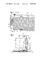
- FIG. 1 is a rear view of a tensioning block according to the invention
- FIG. 2 is a side view of the tensioning block of FIG. 1;
- FIG. 3 is a perspective view of the tensioning block of FIG. 1;
- FIG. 4 is a side view of a single segment of the tensioning block.
- tensioning block 1 which cooperates with a further tensioning block (not shown) in order to provide a stretching and alignment of a fabric 30.
- the tensioning block 1 forms a part of a cross cutting device (not shown), however, I may note that the described block may certainly be used also for other arrangements requiring an alignment of the fabric 30.
- the apparatus has been described for a transverse cutting unit although it is also usable for other textile aligning and orienting purposes.
- the fabric 30 is transported along a conveyor 4 of any suitable design and includes a nap zone 2 which is sectioned by napless zones 3 spaced at a distance to each other along the fabric 30.
- the conveyor 4 operates intermittently so that each time a napless zone which constitutes the zone to be severed is transported to a location beneath the tensioning block 1, the conveyor stops and allows the tensioning and cutting of the fabric 30.
- the tensioning block 1 includes a support member 7 essentially of square cross-section.
- a girder 16a Arranged on the top 7a of the support member 7 is a girder 16a which is fastened thereon by a screw 17a.
- the girder 16a extends transversely to the conveying direction (indicated by arrow A in FIG. 2) of the conveyor 4 and projects beyond the front face 7b of the support member 7.
- a further girder 16b is fastened by a screw 17b to the bottom 7c.
- the girder 16b extends parallel to the girder 16a and projects also beyond the front face 7b of the support member 7.
- a guide plate 10a, 10b is fastened by means of a screw 18a, 18b, respectively, which as in the present embodiment may be a hexagonal head screw.
- a screw 18a, 18b which as in the present embodiment may be a hexagonal head screw.
- Each of the guide plates 10a, 10b extends along the respective girder 16a, 16b and project inwardly toward each other so as to have a distance a (FIG. 3) between the opposing front edges.
- the support member is connected to a not shown drive mechanism in order to be movable between an upper position and a lower position at which an engagement with the fabric 30 is obtained as will be described hereinbelow.
- the support member 7 is provided to hold a plurality of tensioning segments 5 each having a narrow and square main body 15. Arranged at a distance to its forward front portion 14, the main body 15 is provided with two slots 9a, 9b opposing each other and being open toward the outside. By means of the slots 9a, 9b, each segment 5 can be slid along the guide plates 10a, 10b. As is shown in FIG. 3, the opposing ends of the respective slots 9a, 9b have a distance a' from each other which is smaller than the distance a between the opposing edges of the guide plates 10a, 10b projecting into the slots 9a, 9b. Thus, the guide plates 10a, 10b project into the associated slot 9a, 9b with a play.
- each segment 5 is provided at a distance to the girder 16a or respective portion of the support member 7 (FIG. 3) to define a clearance 11.
- each segment 5 can automatically be moved in vertical direction when for example a longitudinal hem or border portion 6 passes which is located along the outer edge of the web of fabric 30. This means, when the fabric 30 is conveyed to the location beneath the tensioning block 1, the respective segments 5 are simply shifted upwardly by the passing hem portion--in the present case the longitudinal hem portion 6 without interfering with the remaining segments 5 engaging the napless zone 3.
- the segments 5 which are already described are movable to a limited degree in vertical direction of the support member 7 are also provided with a limited play in horizontal direction i.e. parallel to the longitudinal elongation of the support member 7.
- the latter play is, however, limited to a necessary degree.
- each segment 5 is provided with a finger-like step-shaped extension 13' at its end facing the fabric 30.
- the extension 13' includes a projecting member 13 and defines a rectangular space of a height corresponding approximately to the height of the nap zone 2. Consequently, when the segments 5 are lowered toward the fabric 30, the projection 13 will engage on the napless zone 3 and slide against the edge of the nap zone 2 when the tensioning block 1 is moved in direction toward the nap zone 2.
- the space 12 then encompasses the respective portion of the nap zone 2 with a certain clearance. Since the projection 13 is relatively narrow and formed almost as a needle, the sliding of the projection 13 on or over the nap zone 2 is prevented.
- the projection 13 is especially advantageous to provide the projection 13 with a width b of approximately 4 mm, a depth t of approximately 2 mm and a length l of approximately 5 mm.
- the guide edge of the projection 13 lying against the nap zone is provided in a sharp-edged manner, in particular in a right-angled manner.
- the fixation of the segments is obtained by a clamping device whose housing portion 22 is connected to the support member 7 by fastening means 21 and which includes a pneumatic working cylinder 8 cooperating with a push rod 20.
- the push rod 20 is shiftable against the outermost segment 5' (FIG. 1) when, e.g., air is admitted into the working cylinder 8 to build up the pressure and to move the push rod 20 accordingly.
- the clamping or fixation of the segments 5 is maintained until the tensioning and the subsequent separating provided by a cross cutting device (not shown) has occurred.
- the pressure in the working cylinder is then released so that the segments 5 are freely movable again.
- the tensioning segments 5 have a width between 4-8 mm.
- the web of fabric 30 which is provided with a plurality of napless zones spaced from each other in elongated direction of the fabric 30 is placed on the conveyor 4 such that the longitudinal hem or border portion 6 extends in conveying direction.
- the conveyor 4 transports the fabric 30 until the most forwardly located napless zone is beneath the pair of tensioning blocks 1 (only one is shown in the drawing). Then the conveyor is stopped and the tensioning blocks 1 are lowered onto the napless zone 3 of the fabric 30 until the associated projection 13 rests thereon. Subsequently, the blocks 1 are moved apart in opposite direction until the projections 13 and thus the segments 5 which are arranged transversely to the conveying direction lie against the nap zone 2 and cause a tensioning of the napless zone.
- the longitudinal hem portion 6 will automatically lift the respective segments 5--as shown in FIG. 1--when the blocks 1 are lowered and shifted so that the tensioning step will not be affected.
- air is admitted into the working cylinder 8 so that the push rod 20 clamps and fixes the arrangement of the segments 5.
- the napless zone is then cut exactly along its center by the cross-cutter.
- the conveyor 4 is actuated to transport the web of fabric 30 until the next napless zone 3 is beneath the blocks 1 so as to repeat the cycle.
- the assembly of the tensioning block 1 is rather simple by sliding the segments from one side along the guide plates 10a, 10b which engage into the respective slots 9a, 9b of the main body 15 of the segments 5.
- the last segment 5 is arranged in the support member 7, e.g. a metal piece can be screwed on to close this side of the block.
- the other side of the block is confined by the clamping device.
- the segments 5 cannot become lost and are supported in such a manner that they can execute a movement nevertheless.
- the tensioning segments are connected to the support member 7, the lower girder 16b serves as support for the segments 5 while--as already mentioned--the upper girder is arranged at a distance to the segments to define the clearance 11.
Landscapes
- Engineering & Computer Science (AREA)
- Life Sciences & Earth Sciences (AREA)
- Forests & Forestry (AREA)
- Mechanical Engineering (AREA)
- Textile Engineering (AREA)
- Treatment Of Fiber Materials (AREA)
Applications Claiming Priority (5)
| Application Number | Priority Date | Filing Date | Title |
|---|---|---|---|
| DE19838327506 DE8327506U1 (de) | 1983-09-24 | 1983-09-24 | Spannleistensegment |
| DE8327505[U] | 1983-09-24 | ||
| DE19838327505 DE8327505U1 (de) | 1983-09-24 | 1983-09-24 | Spannleiste |
| DE8327506[U]DEX | 1983-09-24 | ||
| DE3431210A DE3431210C2 (de) | 1983-09-24 | 1984-08-24 | Spannleiste für Textilbahn-Ausrichtvorrichtungen, insbesondere für eine Querschneidevorrichtung |
Publications (1)
| Publication Number | Publication Date |
|---|---|
| US4609182A true US4609182A (en) | 1986-09-02 |
Family
ID=27192281
Family Applications (1)
| Application Number | Title | Priority Date | Filing Date |
|---|---|---|---|
| US06/653,506 Expired - Lifetime US4609182A (en) | 1983-09-24 | 1984-09-21 | Device for tensioning and aligning a fabric |
Country Status (6)
| Country | Link |
|---|---|
| US (1) | US4609182A (de) |
| DD (1) | DD224631A5 (de) |
| DE (1) | DE3431210C2 (de) |
| FR (1) | FR2553120B1 (de) |
| GB (1) | GB2147237B (de) |
| SE (1) | SE454602B (de) |
Cited By (4)
| Publication number | Priority date | Publication date | Assignee | Title |
|---|---|---|---|---|
| US5299513A (en) * | 1991-09-27 | 1994-04-05 | The Singer Company, Nv | Drawing device for towel cloth |
| US5605266A (en) * | 1994-05-25 | 1997-02-25 | Texpa Arbter Maschinenbaugesellschaft Mbh | Device for aligning material webs |
| US5941149A (en) * | 1996-12-14 | 1999-08-24 | Schmale-Holding Gmbh & Co. | Holddown bar for textile-centering and -cutting machine |
| CN117265859A (zh) * | 2023-09-27 | 2023-12-22 | 安徽华杰鑫森新材料科技有限公司 | 一种无纺布分切机 |
Families Citing this family (2)
| Publication number | Priority date | Publication date | Assignee | Title |
|---|---|---|---|---|
| SE467259B (sv) * | 1987-10-09 | 1992-06-22 | Akab Of Sweden Ab | Anordning foer riktning av avskaerning av en tygbana |
| CN116043516B (zh) * | 2022-12-29 | 2025-08-12 | 吴江嘉伦织造有限公司 | 一种复合弹力布的生产工艺 |
Citations (10)
| Publication number | Priority date | Publication date | Assignee | Title |
|---|---|---|---|---|
| GB711117A (en) * | 1952-08-22 | 1954-06-23 | Brecknell Willis & Co Ltd | Improvements in or relating to forming or profile template |
| US2966086A (en) * | 1955-07-02 | 1960-12-27 | Robert L Sjostrom | Fabric cutting machine |
| US3108508A (en) * | 1960-05-16 | 1963-10-29 | Monroe Calculating Machine | Part locating means for piercing operations |
| FR1374528A (fr) * | 1963-08-30 | 1964-10-09 | Comptoir De L Ind Cotonniere | Machine à couper en trame les serviettes éponge tissées en bandes continues |
| US3192811A (en) * | 1961-07-10 | 1965-07-06 | Sjostrom Automations Inc | Fabric straightening and cutting device |
| GB1239491A (de) * | 1969-04-16 | 1971-07-14 | ||
| GB1277646A (en) * | 1969-07-12 | 1972-06-14 | Temco Tools Ltd | Improvements in or relating to profile inspecting apparatus and methods |
| DE2544410A1 (de) * | 1975-10-03 | 1977-04-07 | Arbter C | Einrichtung zum ausrichten und fadengeraden trennen von stoffbahnen |
| DE3024389A1 (de) * | 1980-06-28 | 1982-01-21 | Carl Schmale Kg, 4434 Ochtrup | Querschneidevorrichtung |
| US4493234A (en) * | 1980-04-03 | 1985-01-15 | Texpa-Arbter Maschinenbaugesellschaft Mbh | Device for straightening and cutting a textile strip |
-
1984
- 1984-08-24 DE DE3431210A patent/DE3431210C2/de not_active Expired
- 1984-09-13 GB GB8423099A patent/GB2147237B/en not_active Expired
- 1984-09-14 SE SE8404605A patent/SE454602B/sv not_active IP Right Cessation
- 1984-09-21 US US06/653,506 patent/US4609182A/en not_active Expired - Lifetime
- 1984-09-21 FR FR8414885A patent/FR2553120B1/fr not_active Expired
- 1984-09-21 DD DD84267497A patent/DD224631A5/de not_active IP Right Cessation
Patent Citations (12)
| Publication number | Priority date | Publication date | Assignee | Title |
|---|---|---|---|---|
| GB711117A (en) * | 1952-08-22 | 1954-06-23 | Brecknell Willis & Co Ltd | Improvements in or relating to forming or profile template |
| US2966086A (en) * | 1955-07-02 | 1960-12-27 | Robert L Sjostrom | Fabric cutting machine |
| US3108508A (en) * | 1960-05-16 | 1963-10-29 | Monroe Calculating Machine | Part locating means for piercing operations |
| US3192811A (en) * | 1961-07-10 | 1965-07-06 | Sjostrom Automations Inc | Fabric straightening and cutting device |
| FR1374528A (fr) * | 1963-08-30 | 1964-10-09 | Comptoir De L Ind Cotonniere | Machine à couper en trame les serviettes éponge tissées en bandes continues |
| GB1239491A (de) * | 1969-04-16 | 1971-07-14 | ||
| GB1277646A (en) * | 1969-07-12 | 1972-06-14 | Temco Tools Ltd | Improvements in or relating to profile inspecting apparatus and methods |
| DE2544410A1 (de) * | 1975-10-03 | 1977-04-07 | Arbter C | Einrichtung zum ausrichten und fadengeraden trennen von stoffbahnen |
| US4034634A (en) * | 1975-10-03 | 1977-07-12 | Arbter C | Apparatus and method for unwinding and cutting a fabric web into individual uniform lengths |
| GB1511785A (en) * | 1975-10-03 | 1978-05-24 | Arbter C | Apparatus for aligning a longitudinal textile web and for severing it in a transverse direction |
| US4493234A (en) * | 1980-04-03 | 1985-01-15 | Texpa-Arbter Maschinenbaugesellschaft Mbh | Device for straightening and cutting a textile strip |
| DE3024389A1 (de) * | 1980-06-28 | 1982-01-21 | Carl Schmale Kg, 4434 Ochtrup | Querschneidevorrichtung |
Cited By (4)
| Publication number | Priority date | Publication date | Assignee | Title |
|---|---|---|---|---|
| US5299513A (en) * | 1991-09-27 | 1994-04-05 | The Singer Company, Nv | Drawing device for towel cloth |
| US5605266A (en) * | 1994-05-25 | 1997-02-25 | Texpa Arbter Maschinenbaugesellschaft Mbh | Device for aligning material webs |
| US5941149A (en) * | 1996-12-14 | 1999-08-24 | Schmale-Holding Gmbh & Co. | Holddown bar for textile-centering and -cutting machine |
| CN117265859A (zh) * | 2023-09-27 | 2023-12-22 | 安徽华杰鑫森新材料科技有限公司 | 一种无纺布分切机 |
Also Published As
| Publication number | Publication date |
|---|---|
| DE3431210C2 (de) | 1986-02-27 |
| GB8423099D0 (en) | 1984-10-17 |
| SE454602B (sv) | 1988-05-16 |
| FR2553120A1 (fr) | 1985-04-12 |
| FR2553120B1 (fr) | 1987-10-30 |
| GB2147237A (en) | 1985-05-09 |
| SE8404605L (sv) | 1985-03-25 |
| SE8404605D0 (sv) | 1984-09-14 |
| DE3431210A1 (de) | 1985-04-18 |
| DD224631A5 (de) | 1985-07-10 |
| GB2147237B (en) | 1987-06-24 |
Similar Documents
| Publication | Publication Date | Title |
|---|---|---|
| US4034634A (en) | Apparatus and method for unwinding and cutting a fabric web into individual uniform lengths | |
| US4068603A (en) | Apparatus for feeding material for forming a double tuck on the cut edges thereof | |
| US5588384A (en) | Method and apparatus of folding opposite ends of a piece of tape | |
| JPS6349266Y2 (de) | ||
| JPH0226984A (ja) | タオル生地の裁断装置 | |
| CN107587275B (zh) | 一种缝纫装置 | |
| US3318179A (en) | Feeding and cutting machine for sheet material | |
| US6231493B1 (en) | Method and apparatus for making a pleat in a sheet-like material | |
| CA1297275C (en) | Apparatus for manufacturing bidirectionally openable slide fasteners | |
| US5280759A (en) | Automatic sewing device | |
| JPH0616958Y2 (ja) | タオル生地の曲り矯正装置 | |
| US3794230A (en) | Work piece guide system | |
| US3003444A (en) | Sewing machine zipper guide | |
| GB2253204A (en) | Laterally registering fed sheets | |
| US6604306B1 (en) | Stitchery frame and method | |
| CN216378637U (zh) | 一种订扣机的导扣装置 | |
| US4616582A (en) | Work clamp for buttonhole sewing machines | |
| JPH11290562A (ja) | ボタン孔かがりミシン | |
| US4638557A (en) | Semi-automatic apparatus for attaching flypieces to a slide fastener chain | |
| KR870000902Y1 (ko) | 긴 슬라이드 파스너 체인의 마무리장치 | |
| DE3024389C2 (de) | Querschneidevorrichtung für Textilbahnen | |
| CN118127722B (zh) | 一种用于缝纫机的带料夹紧组件 | |
| US5259328A (en) | Piping cutter with tensioning shoulders and movable clamp halves and knives | |
| US4051795A (en) | Cloth guide mechanism in a sewing machine | |
| JPS6113289Y2 (de) |
Legal Events
| Date | Code | Title | Description |
|---|---|---|---|
| AS | Assignment |
Owner name: CARL SCHMALE GMBH & CO. KG., LINDHORSTSTR. 12, 443 Free format text: ASSIGNMENT OF ASSIGNORS INTEREST.;ASSIGNOR:FREERMANN, JOHANNES;REEL/FRAME:004318/0038 Effective date: 19840915 |
|
| STCF | Information on status: patent grant |
Free format text: PATENTED CASE |
|
| FEPP | Fee payment procedure |
Free format text: PAYOR NUMBER ASSIGNED (ORIGINAL EVENT CODE: ASPN); ENTITY STATUS OF PATENT OWNER: SMALL ENTITY |
|
| FPAY | Fee payment |
Year of fee payment: 4 |
|
| FPAY | Fee payment |
Year of fee payment: 8 |
|
| FPAY | Fee payment |
Year of fee payment: 12 |
|
| AS | Assignment |
Owner name: CARL SCHMALE GMBH & CO., GERMANY Free format text: ASSIGNMENT OF ASSIGNORS INTEREST;ASSIGNOR:CARL SCHMALE GMBH & CO. KG A.K.A. CARL SCHMALE GMBH A.K.A. CARL SCHMALE KG;REEL/FRAME:009596/0844 Effective date: 19960129 |
|
| AS | Assignment |
Owner name: SCHMALE-HOLDING GMBH & CO., GERMANY Free format text: ASSIGNMENT OF ASSIGNORS INTEREST;ASSIGNOR:CARL SCHMALE GMBH & CO.;REEL/FRAME:009670/0539 Effective date: 19981023 |