US4624520A - Coaxial cable clamp - Google Patents
Coaxial cable clamp Download PDFInfo
- Publication number
- US4624520A US4624520A US06/720,647 US72064785A US4624520A US 4624520 A US4624520 A US 4624520A US 72064785 A US72064785 A US 72064785A US 4624520 A US4624520 A US 4624520A
- Authority
- US
- United States
- Prior art keywords
- connector
- housing
- insulated conductor
- drain wire
- electrical
- Prior art date
- Legal status (The legal status is an assumption and is not a legal conclusion. Google has not performed a legal analysis and makes no representation as to the accuracy of the status listed.)
- Expired - Lifetime
Links
- 239000004020 conductor Substances 0.000 claims abstract description 65
- 238000009413 insulation Methods 0.000 claims abstract description 35
- 230000008878 coupling Effects 0.000 claims description 5
- 238000010168 coupling process Methods 0.000 claims description 5
- 238000005859 coupling reaction Methods 0.000 claims description 5
- 230000013011 mating Effects 0.000 claims description 3
- 230000008676 import Effects 0.000 claims 1
- 238000002955 isolation Methods 0.000 abstract description 2
- 230000005540 biological transmission Effects 0.000 description 3
- 230000001681 protective effect Effects 0.000 description 3
- 230000004308 accommodation Effects 0.000 description 2
- 238000013459 approach Methods 0.000 description 2
- DMFGNRRURHSENX-UHFFFAOYSA-N beryllium copper Chemical compound [Be].[Cu] DMFGNRRURHSENX-UHFFFAOYSA-N 0.000 description 2
- 238000004891 communication Methods 0.000 description 2
- 238000010276 construction Methods 0.000 description 2
- 239000000463 material Substances 0.000 description 2
- 238000000034 method Methods 0.000 description 2
- 238000010079 rubber tapping Methods 0.000 description 2
- 239000011888 foil Substances 0.000 description 1
- 238000009434 installation Methods 0.000 description 1
- 230000002452 interceptive effect Effects 0.000 description 1
- 229910052751 metal Inorganic materials 0.000 description 1
- 239000002184 metal Substances 0.000 description 1
Images


Classifications
-
- H—ELECTRICITY
- H01—ELECTRIC ELEMENTS
- H01R—ELECTRICALLY-CONDUCTIVE CONNECTIONS; STRUCTURAL ASSOCIATIONS OF A PLURALITY OF MUTUALLY-INSULATED ELECTRICAL CONNECTING ELEMENTS; COUPLING DEVICES; CURRENT COLLECTORS
- H01R9/00—Structural associations of a plurality of mutually-insulated electrical connecting elements, e.g. terminal strips or terminal blocks; Terminals or binding posts mounted upon a base or in a case; Bases therefor
- H01R9/03—Connectors arranged to contact a plurality of the conductors of a multiconductor cable, e.g. tapping connections
- H01R9/05—Connectors arranged to contact a plurality of the conductors of a multiconductor cable, e.g. tapping connections for coaxial cables
-
- H—ELECTRICITY
- H01—ELECTRIC ELEMENTS
- H01R—ELECTRICALLY-CONDUCTIVE CONNECTIONS; STRUCTURAL ASSOCIATIONS OF A PLURALITY OF MUTUALLY-INSULATED ELECTRICAL CONNECTING ELEMENTS; COUPLING DEVICES; CURRENT COLLECTORS
- H01R4/00—Electrically-conductive connections between two or more conductive members in direct contact, i.e. touching one another; Means for effecting or maintaining such contact; Electrically-conductive connections having two or more spaced connecting locations for conductors and using contact members penetrating insulation
- H01R4/24—Connections using contact members penetrating or cutting insulation or cable strands
- H01R4/2416—Connections using contact members penetrating or cutting insulation or cable strands the contact members having insulation-cutting edges, e.g. of tuning fork type
Definitions
- This invention relates generally to an electrical termination device for coaxial cable and more particularly pertains to an impedance-matched low capacitance connector for coaxial cable which provides data transmission to computer terminal or similar devices.
- the cable used to serve computer terminals in a LAN system is typically a coaxial cable having an insulated center conductor, a non-insulated drain wire, an electrically conductive shield and an outer insulated jacket.
- Various connector designs have been used to make connections to this type of coaxial cable.
- One series of connectors requires stripping of the outer insulative jacket separating the shield, the drain wire and the insulative conductor and further stripping of the insulative conductor to make effective electrical connection.
- Other approaches include insulation displacing techniques which will make connection to the cable without necessity for stripping the outer insulative jacket.
- the present invention has as its object the provision of simplified connection of coaxial cable to an electrical connector.
- the present invention provides an electrical connector for coaxial cable having an elongate conductive body which accommodates both an insulative conductor and a drain wire of the coaxial cable.
- An insulation displacing electrical contact is supported in the body for electrical engagement with the insulative conductor.
- a clamping element is removably supported on the body for clamping the insulated center conductor between the insulation displacing portions of the electrical contact and the clamping body, securing means is included for engaging the clamping element and moving the clamping element to force the insulated center conductor into insulation displacing electrical engagement with the electrical contact.
- the drain wire may be inserted between the clamping element and the securing means to provide electrical continuity to the connector body and thereby an impedance matched shielded connection.
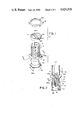
- FIG. 1 is an exploded perspective view of the component parts of coaxial cable tap of the present invention.
- FIG. 2 is a vertical section of the body portion of coaxial cable tap of FIG. 1., taken along the lines II--II.
- FIG. 3 is a perspective view of a type of cable to be tapped by the connector of FIG. 1, the cable being shown with its insulated center conductor, shield and drain wire partially withdrawn from its protective casing.
- FIG. 4 is a front electrical showing of a portion of the connector of FIG. 1, prior to full assembly including the cable center conductor and drain wire therein.
- FIG. 5 is a front elevational showing of the assembled connector of FIG. 1, including the cable center conductor and drain wire therein.
- FIG. 6 shows in perspective view the assembled cable connector of FIG. 1 tapping a cable shown in FIG. 3.
- connector 10 includes housing 12, clamping member 14, and assembly nut 16, all constructed of electrically conductive material, such as beryllium copper.
- Housing 12 is an elongate generally hollow cylindrical member, having at one end a cable engagement portion 18, and at the other end a connector engagement portion 24. Centrally located between cable engagement portion 18 and connector engament portion 24 is a hexagonally shaped central shoulder 22 which when used with an appropriate tool facilitate installation of connector 10.
- Cable engagement portion 18 includes a pair of diametrically opposed upwardly opening vertical slots 20, which provides a cable entry opening, as will be described in greater detail hereinbelow. Slots 20 extend from the base of connector engagement portion 18 to the distal extend thereof. Cable engagement portion 18 is exterally screw threaded for mating accommodation with further connector parts as will be described hereinbelow.
- Connector engagement portion 24 accommodates, at its lower distal end, a connection sleeve 26.
- Connection sleeve 26 is of conventional construction and rotatably supported on connector engagement portion 24 for external connection.
- An outwardly depending shoulder 24a of connector engaging 24 cooperates with an inwardly directed flange 26a of connector sleeve 26 to provide for the rotative securement of connector sleeve 26 on connector engaging portion 24.
- connection sleeve 26 is moveable vertically in the direction of arrow A along connector engaging portion 24.
- Connection sleeve 26 may be internally screw threaded for cooperative connection with a externally threaded coaxial termination of a tranceiver or other electrical device.
- Insulative support member 30 is supported in the hollow central portion of connector engaging portion 24.
- Insulative support member 30 may be formed of any suitable insulative material, such as plastic and more specifically polypropelene.
- Insulative support member 30 serves to support and electrically isolate, insulation displacing contact 35, centrally accommodated in housing 12 of connector 10.
- Contact element 35 is formed of suitably conductive material such as beryllium copper.
- Contact element 35 is an elongate member having an upper insulation displacing end portion 35a, including a pair of insulation displacing teeth 36 and 38.
- Opposite contact element end portion 40 is of the female coaxial connection type and includes a central channel 42 for accommodating a stinger or pin of a male mating coaxial connector (not shown).
- end portion 40 can be of any conventional construction. As shown in FIGS. 1 and 2, the insulation displacing portions 36 and 38 of contact element 35 extend above the upper surface 30a of insulated support member 30 and are aligned with each of the vertical slots 20.
- the clamping member 14 is a washer type element having an annular body 44.
- a diametrically extending cross member 46 spans body 44 and is dimensioned to be accomodated in the vertical slots 20 of cable engagement portion 18 of connector 10. Adjacent each diametrical extent of cross member 46 are a pair of downwardly opening conductor accommodating recesses 48, which are also alignable with slots 20.
- Diametrical cross member 46 further includes on the upper surface thereof an elongate V-shaped channel 46a, the use and function of which will be described in greater detail hereinbelow.
- the final component of connector 10 is the assembly nut 16, which is internally screw threaded at 16a for screw accommodation on cable engagement portion 18. Assembly nut 16 securely supports clamping member 14 on cable engagement portion 18.
- Cable 50 which may be tapped into or end terminated with connector 10.
- Cable 50 which is more fully described in the above mentioned commonly assigned U.S. Pat. No. 4,404,425, includes a resilient protective casing 52 of electrically insulative material and a coaxial cable assembly therein, comprising an insulated conductor 54, a drain wire 56, an electrically conductive outer sheath 58, which surrounds insulated conductor 54 and drain wire 56.
- a metal foil type conductive sheath is shown, however, the sheath may also be formed of conventional braided wire.
- the drain wire 56 is in intimate contact with sheath 58 and therefore at the same electrical potential.
- the drain wire 56 and sheath 58 are typically placed at ground potential to serve as an effective electrical shield for cable 50.
- the cable 50 of FIG. 3, is shown prepared for tapping into a central portion thereof.
- the insulated conductor 54, drain wire 56 and electrically conductive sheath 58 have been removed from a central portion of protective casing 52.
- the insulated conductor 54 may be inserted into cable engagement portion 18 between vertical slots 20.
- the cable is inserted into vertical slots 20 until a transverse extent of the cable abuts the insulation displacing portion 35a. of contact element 35.
- Clamping member 14 is then brought down over insulated conductor 54 with the cross member 46 being accomodated between vertical slots 20.
- Drain wire 56 is then inserted into cable engagement portion 18 through vertical slots 20. The drain wire is accommodated in the V-shaped channel 46a Assembly nut 16 is then screw threaded onto upper end of cable engagement portion 18.
- the assembly nut 16 may then be either hand tightened or tightened by use of a suitable tool, such as a wrench, until it bears against the drain wire 56 and forces the drain wire into intimate contact with clamping member 14.
- a suitable tool such as a wrench
- the drain wire being positionally confined by the V-shaped recess 46a and will not twist or turn upon rotation of assembly nut 16.
- Further tightening of assembly nut 16 forces it into contact with clamping member 14 which in turn is forced downward onto insulated conductor 54 being accommodated in downwardly opening recesses 48.
- Still further movement of assembly nut 16 progressively urges clamping member 14 and insulated conductor 54 downward whereupon the insulated conductor is forced onto insulation displacing teeth 36 and 38 of contact 35.
- Insulated conductor 54 will then be electrically connected to contact element 35 in conventional insulation displacing fashion.
- the drain wire 56 being sandwiched between assembly nut 16 and clamping member 14 will be in electrical connection therewith and also in electrical connection with conductive housing 12.
- the connector 10, as shown in FIG. 5, is now at the same electrical potential as drain wire 56, which is typically placed at ground potential for shielding purposes. Thus, connector 10 will serve as an electrical shield for the coaxial cable tap.
- Contact element 35 being supported in insulative support member 30, is electrically isolated from the remainder of the connector and therefore connects directly to insulative conductor 54 without interfering with or coupling to the electrical shield.
- connector 10 also supports insulated conductor 54 in fixed position in electrical connection with contact element 35.
- Clamping member 14 is seated against shoulder 22 and held in positional confinement by assembly nut 16.
- Conductor 54 electrically terminated on insulation display portion 35a, is prevented from becoming dislodged from its position therein as the clamping member 14 bears directly on insulated conductor 54.
- An undersurface 46b of cross member 46 contacts the insulation of insulated conductor 54 preventing upward withdrawal thereof.
- Recesses 48 accommodate a transverse extention of insulated conductor 54.
- the insulated conductor 54 will extend through each recess 48 and vertical slot 20 of drawing 12, and be vertically positionally confined therein.
- assembly nut 16 is securely fastened to threaded portion 18, insulated conductor 54 will not vibrate loose from its electrical connection with contact 35.
- the assembled connector 10 mechanically and electrically supports both insulated conductor 54 and drain wire 56. It is further contemplated that a portion of the shield 58 may be wedged between clamping member 14 and assembly nut 16 to further provide electrical shield connection with the connector housing 12. However, as the drain wire is in intimate contact with the shield along the length of cable 50, connection of the shield 58 is not essential for continuous shielding.
- an insulative connector housing (not shown) may be used to enclose both connector 10 and a longitudinal extent of cable 50 adjacent connector 10.
- Connector sleeve 26 would remain external of the housing in order to provide for coupling of connection 10 to a transceiver, another coaxially terminated cable or electronic device.
Landscapes
- Coupling Device And Connection With Printed Circuit (AREA)
- Multi-Conductor Connections (AREA)
- Details Of Connecting Devices For Male And Female Coupling (AREA)
- Connections By Means Of Piercing Elements, Nuts, Or Screws (AREA)
Priority Applications (5)
| Application Number | Priority Date | Filing Date | Title |
|---|---|---|---|
| US06/720,647 US4624520A (en) | 1985-04-08 | 1985-04-08 | Coaxial cable clamp |
| EP86104047A EP0197420A3 (de) | 1985-04-08 | 1986-03-24 | Koaxialkabelklammer |
| CA000506101A CA1236191A (en) | 1985-04-08 | 1986-04-08 | Coaxial cable clamp |
| AU55752/86A AU571779B2 (en) | 1985-04-08 | 1986-04-08 | Connector for coaxial cable |
| JP61079338A JPS61277174A (ja) | 1985-04-08 | 1986-04-08 | 電気ケ−ブルのコネクタ |
Applications Claiming Priority (1)
| Application Number | Priority Date | Filing Date | Title |
|---|---|---|---|
| US06/720,647 US4624520A (en) | 1985-04-08 | 1985-04-08 | Coaxial cable clamp |
Publications (1)
| Publication Number | Publication Date |
|---|---|
| US4624520A true US4624520A (en) | 1986-11-25 |
Family
ID=24894786
Family Applications (1)
| Application Number | Title | Priority Date | Filing Date |
|---|---|---|---|
| US06/720,647 Expired - Lifetime US4624520A (en) | 1985-04-08 | 1985-04-08 | Coaxial cable clamp |
Country Status (5)
| Country | Link |
|---|---|
| US (1) | US4624520A (de) |
| EP (1) | EP0197420A3 (de) |
| JP (1) | JPS61277174A (de) |
| AU (1) | AU571779B2 (de) |
| CA (1) | CA1236191A (de) |
Cited By (7)
| Publication number | Priority date | Publication date | Assignee | Title |
|---|---|---|---|---|
| US4764124A (en) * | 1987-04-20 | 1988-08-16 | Guy Simon | Self stripping connection device |
| US4850895A (en) * | 1987-09-10 | 1989-07-25 | Fujikura Ltd. | Coaxial cable connection assembly with a transceiver |
| US6210222B1 (en) | 1999-12-13 | 2001-04-03 | Eagle Comtronics, Inc. | Coaxial cable connector |
| US6669515B1 (en) * | 2002-12-20 | 2003-12-30 | Bellsouth Intellectual Property Corporation | Apparatus for securing cable |
| EP2710670A4 (de) * | 2011-05-17 | 2014-11-19 | 3M Innovative Properties Co | Antennenanordnung für ein konvergiertes netzwerk innerhalb eines gebäudes |
| CN104282450A (zh) * | 2014-10-10 | 2015-01-14 | 潞安职业技术学院 | 一种防爆高开卡爪 |
| US20170149378A1 (en) * | 2015-11-20 | 2017-05-25 | Hubbell Incorporated | Solar panel and grounding connectors |
Families Citing this family (2)
| Publication number | Priority date | Publication date | Assignee | Title |
|---|---|---|---|---|
| JPH0621165U (ja) * | 1991-12-13 | 1994-03-18 | 橋本 幸夫 | 端子接続装置 |
| GB2333909A (en) * | 1998-01-28 | 1999-08-04 | Microm Electronics Ltd | Control apparatus and connector for refrigeration system |
Citations (14)
| Publication number | Priority date | Publication date | Assignee | Title |
|---|---|---|---|---|
| US2322702A (en) * | 1929-06-24 | 1943-06-22 | Thomas F Peterson | Shielded cable |
| US2642474A (en) * | 1949-09-14 | 1953-06-16 | Honeywell Regulator Co | Electrical connector |
| US2805399A (en) * | 1955-10-04 | 1957-09-03 | William W Leeper | Connector for uniting coaxial cables |
| US2843827A (en) * | 1955-04-08 | 1958-07-15 | Isaac S Blonder | Electrical-line tapper |
| US2963676A (en) * | 1957-09-16 | 1960-12-06 | Electriduct Company | Electrical outlet |
| US3187290A (en) * | 1962-10-01 | 1965-06-01 | Electriduct Company | Outlet for a floor duct |
| US3295076A (en) * | 1964-08-17 | 1966-12-27 | Bendix Corp | Electrical connector means for coaxial cables and the like |
| US3332052A (en) * | 1965-02-26 | 1967-07-18 | United Carr Inc | Electrical connector component with grounding crown contact |
| US3372361A (en) * | 1965-06-15 | 1968-03-05 | Fargo Mfg Co Inc | Cable connector |
| US3585571A (en) * | 1969-04-24 | 1971-06-15 | Raymond G Davis | Electric wire connector with insulation piercing means |
| US3594703A (en) * | 1969-10-13 | 1971-07-20 | Amp Inc | Electrical tapoff connector |
| US4365859A (en) * | 1980-08-22 | 1982-12-28 | Bunker Ramo Corporation | Coaxial tap connector |
| US4469391A (en) * | 1981-10-13 | 1984-09-04 | Thomas & Betts Corporation | Coaxial cable connector |
| US4502749A (en) * | 1983-12-01 | 1985-03-05 | Amp Incorporated | Coaxial connector for microwave packages |
Family Cites Families (2)
| Publication number | Priority date | Publication date | Assignee | Title |
|---|---|---|---|---|
| GB1348806A (en) * | 1971-05-20 | 1974-03-27 | C S Antennas Ltd | Coaxial connectors |
| US4588249A (en) * | 1982-11-03 | 1986-05-13 | Amp Incorporated | Coaxial cable tap connector |
-
1985
- 1985-04-08 US US06/720,647 patent/US4624520A/en not_active Expired - Lifetime
-
1986
- 1986-03-24 EP EP86104047A patent/EP0197420A3/de not_active Withdrawn
- 1986-04-08 CA CA000506101A patent/CA1236191A/en not_active Expired
- 1986-04-08 JP JP61079338A patent/JPS61277174A/ja active Pending
- 1986-04-08 AU AU55752/86A patent/AU571779B2/en not_active Ceased
Patent Citations (14)
| Publication number | Priority date | Publication date | Assignee | Title |
|---|---|---|---|---|
| US2322702A (en) * | 1929-06-24 | 1943-06-22 | Thomas F Peterson | Shielded cable |
| US2642474A (en) * | 1949-09-14 | 1953-06-16 | Honeywell Regulator Co | Electrical connector |
| US2843827A (en) * | 1955-04-08 | 1958-07-15 | Isaac S Blonder | Electrical-line tapper |
| US2805399A (en) * | 1955-10-04 | 1957-09-03 | William W Leeper | Connector for uniting coaxial cables |
| US2963676A (en) * | 1957-09-16 | 1960-12-06 | Electriduct Company | Electrical outlet |
| US3187290A (en) * | 1962-10-01 | 1965-06-01 | Electriduct Company | Outlet for a floor duct |
| US3295076A (en) * | 1964-08-17 | 1966-12-27 | Bendix Corp | Electrical connector means for coaxial cables and the like |
| US3332052A (en) * | 1965-02-26 | 1967-07-18 | United Carr Inc | Electrical connector component with grounding crown contact |
| US3372361A (en) * | 1965-06-15 | 1968-03-05 | Fargo Mfg Co Inc | Cable connector |
| US3585571A (en) * | 1969-04-24 | 1971-06-15 | Raymond G Davis | Electric wire connector with insulation piercing means |
| US3594703A (en) * | 1969-10-13 | 1971-07-20 | Amp Inc | Electrical tapoff connector |
| US4365859A (en) * | 1980-08-22 | 1982-12-28 | Bunker Ramo Corporation | Coaxial tap connector |
| US4469391A (en) * | 1981-10-13 | 1984-09-04 | Thomas & Betts Corporation | Coaxial cable connector |
| US4502749A (en) * | 1983-12-01 | 1985-03-05 | Amp Incorporated | Coaxial connector for microwave packages |
Cited By (8)
| Publication number | Priority date | Publication date | Assignee | Title |
|---|---|---|---|---|
| US4764124A (en) * | 1987-04-20 | 1988-08-16 | Guy Simon | Self stripping connection device |
| US4850895A (en) * | 1987-09-10 | 1989-07-25 | Fujikura Ltd. | Coaxial cable connection assembly with a transceiver |
| US6210222B1 (en) | 1999-12-13 | 2001-04-03 | Eagle Comtronics, Inc. | Coaxial cable connector |
| US6669515B1 (en) * | 2002-12-20 | 2003-12-30 | Bellsouth Intellectual Property Corporation | Apparatus for securing cable |
| EP2710670A4 (de) * | 2011-05-17 | 2014-11-19 | 3M Innovative Properties Co | Antennenanordnung für ein konvergiertes netzwerk innerhalb eines gebäudes |
| US8947319B2 (en) | 2011-05-17 | 2015-02-03 | 3M Innovative Properties Company | Antenna assembly for converged in-building network |
| CN104282450A (zh) * | 2014-10-10 | 2015-01-14 | 潞安职业技术学院 | 一种防爆高开卡爪 |
| US20170149378A1 (en) * | 2015-11-20 | 2017-05-25 | Hubbell Incorporated | Solar panel and grounding connectors |
Also Published As
| Publication number | Publication date |
|---|---|
| JPS61277174A (ja) | 1986-12-08 |
| EP0197420A3 (de) | 1989-03-22 |
| AU5575286A (en) | 1986-10-16 |
| EP0197420A2 (de) | 1986-10-15 |
| AU571779B2 (en) | 1988-04-21 |
| CA1236191A (en) | 1988-05-03 |
Similar Documents
| Publication | Publication Date | Title |
|---|---|---|
| EP0270473B1 (de) | Hochspannungskabelverbinder | |
| EP0632932B1 (de) | Verbinder zum anschluss koaxialer kabel verschiedener querschnittsabmessungen | |
| CA2046400A1 (en) | Torqueable guide wire assembly with electrical functions, male and female connectors for use therewith and system and apparatus for utilizing the same | |
| CA2001957A1 (en) | Guide wire assembly with electrical functions and male and female connectors for use therewith | |
| US5722840A (en) | Conductor protector | |
| JPH0658814B2 (ja) | 導体の接続装置 | |
| CA1292787C (en) | Spindle-receiving jack for forming an electrical connection and electrical connector comprising at least one such jack | |
| US4730385A (en) | Coax connector installation tool | |
| WO1987005447A1 (en) | A cable jointing clamp | |
| US5928008A (en) | Earthing module | |
| US4624520A (en) | Coaxial cable clamp | |
| US4659164A (en) | Diode connector | |
| CA2079346A1 (en) | Coaxial connector | |
| US4746307A (en) | Coaxial cable transmission system | |
| EP1642362B1 (de) | Koaxialkontakt | |
| EP0148394B1 (de) | Gekapselte Schaltanlagen | |
| EP0198218A3 (de) | Koaxialkabelendstück | |
| WO1991011040A1 (en) | Cable connector | |
| US4432592A (en) | Electrical connector assembly | |
| EP0251396B1 (de) | Abzweigungsverbindung für Koaxialkabel | |
| US7210947B1 (en) | Cable harness system, ground clips and method for electrically grounding a conductor of the cable harness system | |
| US5888095A (en) | Coaxial cable connector | |
| EP0311226B1 (de) | Koaxialer Kabelverbindungszusammenbau mit einem Sender-Empfänger | |
| US5071366A (en) | Circular IDC connector | |
| EP0154179A3 (en) | Connection of conductors especially for high current terminals |
Legal Events
| Date | Code | Title | Description |
|---|---|---|---|
| AS | Assignment |
Owner name: THOMAS & BETTS CORPORATION, 920 ROUTE 202, RARITAN Free format text: ASSIGNMENT OF ASSIGNORS INTEREST.;ASSIGNOR:BLUM, KENNETH P.;REEL/FRAME:004395/0749 Effective date: 19850408 |
|
| STCF | Information on status: patent grant |
Free format text: PATENTED CASE |
|
| CC | Certificate of correction | ||
| FEPP | Fee payment procedure |
Free format text: PAYOR NUMBER ASSIGNED (ORIGINAL EVENT CODE: ASPN); ENTITY STATUS OF PATENT OWNER: LARGE ENTITY |
|
| FPAY | Fee payment |
Year of fee payment: 4 |
|
| REMI | Maintenance fee reminder mailed | ||
| FPAY | Fee payment |
Year of fee payment: 8 |
|
| SULP | Surcharge for late payment | ||
| FEPP | Fee payment procedure |
Free format text: PAYER NUMBER DE-ASSIGNED (ORIGINAL EVENT CODE: RMPN); ENTITY STATUS OF PATENT OWNER: LARGE ENTITY Free format text: PAYOR NUMBER ASSIGNED (ORIGINAL EVENT CODE: ASPN); ENTITY STATUS OF PATENT OWNER: LARGE ENTITY |
|
| FPAY | Fee payment |
Year of fee payment: 12 |
|
| AS | Assignment |
Owner name: THOMAS & BETTS INTERNATIONAL, INC., NEVADA Free format text: ASSIGNMENT OF ASSIGNORS INTEREST;ASSIGNOR:THOMAS & BETTS CORPORATION;REEL/FRAME:009534/0734 Effective date: 19981007 |