US4630236A - Cassette-type magnetic bubble memory - Google Patents
Cassette-type magnetic bubble memory Download PDFInfo
- Publication number
- US4630236A US4630236A US06/529,638 US52963883A US4630236A US 4630236 A US4630236 A US 4630236A US 52963883 A US52963883 A US 52963883A US 4630236 A US4630236 A US 4630236A
- Authority
- US
- United States
- Prior art keywords
- cassette
- magnetic bubble
- lid
- slider
- holder
- Prior art date
- Legal status (The legal status is an assumption and is not a legal conclusion. Google has not performed a legal analysis and makes no representation as to the accuracy of the status listed.)
- Expired - Lifetime
Links
Images





Classifications
-
- G—PHYSICS
- G11—INFORMATION STORAGE
- G11C—STATIC STORES
- G11C19/00—Digital stores in which the information is moved stepwise, e.g. shift registers
- G11C19/02—Digital stores in which the information is moved stepwise, e.g. shift registers using magnetic elements
- G11C19/08—Digital stores in which the information is moved stepwise, e.g. shift registers using magnetic elements using thin films in plane structure
- G11C19/085—Generating magnetic fields therefor, e.g. uniform magnetic field for magnetic domain stabilisation
Definitions
- the present invention relates to a magnetic bubble memory, and more particularly to a magnetic bubble memory which employs a cassette-type magnetic bubble device for controlling the magnetic bubble to store and transfer information and which mounts the magnetic bubble cassette on a cassette holder connector.
- Another object of the present invention is to provide a construction which allows easy mounting and detachment of the cassette, prevents faulty contacts and faulty connections, allows easy repair of the faulty connections and reinstating of the cassette, and prevents actuation of the magnetic bubble device in case of faulty connection.
- the present invention provides an improvement of a magnetic bubble memory having a cassette comprising a magnetic bubble chip, a driving coil, a bias magnet, and associated elements, contained in a case and provided with a connector and having a holder capable of holding the magnetic bubble cassette by the connectors.
- the improvement comprises a mechanism for ejecting the cassette from the cassette pocket of the holder, an ejecting button for operating the ejecting mechanism, a lid of a size which is sufficiently large to close the cassette inlet of the cassette pocket as well as to cover the ejecting button and which is provided in front of the cassette inlet of the cassette pocket, and a means to generate an electric signal corresponding to the position of the lid.
- FIG. 1 is a perspective view of a magnetic bubble cassette with the lid closed
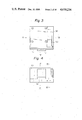
- FIG. 2 is a perspective view of the magnetic bubble cassette with the lid opened
- FIG. 3 is a plan view of the holder
- FIG. 4 is a partly broken front elevation of the holder
- FIG. 5 is a side elevation of the left side of the holder
- FIG. 6 is a side elevation of the right side of the holder
- FIG. 7 is a front elevation of the holder with its cover opened
- FIG. 8 is a sectional view taken along line VIII--VIII of FIG. 10;
- FIG. 9 is a sectional view taken along line IX--IX of FIG. 10;
- FIG. 10 is a bottom plan view of the holder
- FIGS. 11 and 12 are schematic illustrations of another embodiment of a discharging spring of the slider
- FIGS. 13, 14, and 15 are schematic illustrations of embodiments of cassette popping prevention mechanisms
- FIG. 16 is a perspective view of a part (the slider) of the cassette popping prevention mechanism of FIG. 15;
- FIG. 17 is a schematic illustration of a mechanism for detecting the position of the cover of the holder.
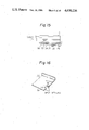
- FIGS. 18 and 19 are schematic illustrations of a cassette insertion detecting mechanism.
- a magnetic bubble domain device including a magnetic bubble chip, a driving coil, a bias magnet, and associated elements, is contained within a cassette C comprising a top cover 1a and a bottom cover 1b, as shown in FIGS. 1 and 2.
- the cassette C is provided on the front side thereof with a swing lid 2. Opening the lid 2 exposes a connector 3 as shown in FIG. 2.
- the height h 1 of the top cover 1a is larger than the height h 2 of the bottom cover 1b.
- the cassette C is asymmetric with respect to the junction plane between the top cover 1a and the bottom cover 1b.
- Grooves 4 for ensuring correct insertion of the cassette are formed along the joint of the top and the bottom covers 1a and 1b.
- a grounding metal piece 5 is disposed in the bottom surface of the groove 4, while a grounding spring 6 is secured to the holder so as to be pressed against the grounding metal piece 5.
- the groove 4 and the grounding metal piece 5 are provided on each side wall of the cassette C.
- Recesses 7 for locking or for position detection are formed in the edges between the bottom wall and the right and the left side walls of the cassette, respectively.
- Two parallel relief grooves 8 are formed in the top wall of the cassette.
- the two fingers 9 of the lid 2 are rotatably supported and can be inserted into the extremities of the relief grooves 8. Normally, the lid 2 is urged in the closing direction by means of a torsion spring (not shown).
- a holder H for receiving and holding the cassette C is provided on the front side thereof with a lid 10, as shown in FIG. 4.
- the pivotal shaft 11 of the lid 10 is provided at the upper end of the lid 10, as shown in FIGS. 5, 6, 8, and 9.
- a toggle spring 12 for the toggle motion of the lid 10 is arranged between the lid 10 and the body of the holder H, such that, when the lid 10 is closed, the toggle spring 12 is situated somewhat toward the lid 10 to urge the lid 10 in a closing direction.
- the toggle spring 12 urges the lid 10 in an opening direction after the toggle spring 12 has moved backward enough to pass the pivotal shaft 11, so that the lid 10 can easily and surely be opened and closed.
- Opening the lid 10 exposes a cassette pocket 14, as shown in FIG. 7.
- a connector 16 is secured to the holder body 15 at the innermost position of the pocket 14.
- the cassette C With the lid 10 of the holder opened, the cassette C is inserted through a cassette inlet 14i into the pocket 14 along a direction indicated by the arrow a 1 .
- the connector 16 provided within the pocket 14 and the connector 3 of the cassette C are interconnected.
- a printed circuit board Pc is fixed to and electrically connected to the connector 16. Peripheral circuits, such as control circuits of the magnetic bubble device, are formed in the printed circuit board Pc.
- Two ribs 18 corresponding to the relief grooves 8 of the cassette C are formed on the inside surface of the top panel 17 of the pocket 14 parallel to the direction of insertion of the cassette.
- the fingers 9 of the cassette C are brought into abutment with the outer ends 18a (FIG. 8) of the ribs 18 and then pushed down by a force applied thereto in the direction of the arrow a 2 (FIG. 1).
- the ribs 18 slide over the fingers 9 of the lid 2 and along the relief grooves 8 as the cassette is inserted further into the pocket.
- the lid 2 of the cassette which is normally closed is opened immediately before the connectors 16 and 3 are interconnected.
- horizontal ribs 19 are formed on the right and the left side walls of the pocket 14 so as to be engaged with the right and the left grooves 4 of the cassette to guide the cassette as the cassette is inserted into the pocket 14 and to prevent the reverse insertion of the cassette into the pocket 14.
- the cassette can be pushed by hand when inserting it into the pocket 14 through the cassette inlet 14i.
- An ejection button 20 is pushed in the direction of the arrow a 1 for discharging the cassette from the pocket 14.
- a cassette inserting mechanism and a cassette ejecting mechanism will be discribed hereunder.
- a slider 22 is placed on the inside surface of the bottom panel 21 of the pocket 14.
- the inner end (the end on the side of the connector 16) of the slider 22 is bent vertically upward to form an integral stop plate 23.
- the cassette is placed on the slider 22 when being inserted into the pocket 14.
- a slit 24 extending along the direction of the insertion of the cassette is formed in the bottom panel 21, as shown in FIGS. 8 and 10.
- Two rollers 25 and 26 are secured to the slider 22 at an interval and provided over the slit 24.
- a slit 27 extending in the direction of the front-back motion of the ejecting button 20 is formed also in the bottom panel 21 in parallel to the slit 24.
- Two rollers 29 and 30 are attached to the stem 28 of the ejecting button 20 and fitted in and over the slit 27.
- a lever 32 is supported rotatably on the bottom panel 21 by means of a pivotal shaft 31. One end 32a of the lever is held between the rollers 29 and 30 attached to the stem 28 of the ejecting button 20, while the other end 32b is located between the rollers 25 and 26 attached to the slider 22.
- a return spring 33 urges the rollers 29 and 30 and the ejecting button 20 in the returning direction (reverse to the direction of the arrow a 1 ) through the lever 32.
- An ejection torsion spring 35 engages a pin 34 fixed to a part of the slider 22 exposed to the slit 24 and a pin 36 fixed to the bottom panel 21 to urge the slider 22 in the direction of ejecting the cassette (the direction of the arrow a 3 ).
- the slider 22 In the position shown in FIG. 10, the slider 22 is in the full stroke innermost position.
- the ejection button 20 is pushed in the direction of the arrow a 1 against the resilient force of the spring 33, the slider 22 is retracted by the resilient force of the ejection spring 35 by a distance St to a position shown by a dotted line.
- the ejecting spring 35 moves to a position shown by broken lines.
- the front end of the cassette comes in contact with the stop plate 23. Since the resilient force of the ejection spring 35 is acting on the slider 22 in the direction of the arrow a 3 , the cassette needs to be pushed further against the resilient force of the ejection torsion spring 35. Then, the slider 22 advances together with the cassette from the position shown by a dotted line in FIG. 10 to a position shown by solid lines in FIG. 8 or a broken line in FIG. 10.
- the cassette mounted in the pocket 14 can be discharged simply by pushing the ejection button 20 against the resilient force of the return spring 33 in the direction indicated by the arrow a 1 in FIG. 9.
- the ejection button 20 When the ejection button 20 is depressed, the right end 32a of the lever 32 is moved from the position shown in FIG. 10 in the direction indicated by the arrow a 1 , whereby the roller 26 is pushed in the direction indicated by the arrow a 3 , so that the slider 22 is pushed back toward the cassette inlet 14i. Consequently, the stop plate 23 of the slider 22 pushes the cassette in a direction reverse to the direction indicated by the arrow a 1 to separate the connector 3 from the connector 16 and to eject the cassette through the cassette inlet 14i.
- the length between the pivotal shaft 31 and the right end 32a of the lever 32 is longer than the length between the pivotal shaft 31 and the left end 32b of the lever 32 so that, with the help of the use of such leverage, a small force is effective to drive the slider 22 and to disconnect the connectors 3 and 16 from each other.
- the relative length between the pivotal shaft 31 and the left end 32b of the lever 32 should be reduced. As a result, the stroke of the left end 32b of the lever 32 is also reduced.
- the slider 22 and the cassette carried thereon can be effectively discharged by the snapping force of the ejection torsion spring 35, where the associated mechanism is constituted so that the direction of the action of the snapping force of the ejecting spring 35 is inverted within the range of the stroke of the left end 32b of the lever 32.
- the increase in the stroke of the slider 22 by the agency of the ejecting spring 35 compensates for the reduction in the stroke of the left end 32b of the lever 32.
- an extension coil spring 35a instead of such a torsion spring.
- one end of a swing plate 45 is connected pivotably at 47 to the bottom panel 21, while the other end thereof is connected pivotably to the slider 22 at 46 and an extension coil spring 35a is extended between the end 46 of the swing plate 45 and a predetermined position on the bottom panel 21. That is, when the coil spring 35a is positioned on the side of the lever 32 with respect to the pivotal axis 47 thereof, as illustrated in FIG. 11, the coil spring 35a biases the slider 22 toward the connector 16.
- the slider 22 may be formed in a box-shape to receive the cassette therein for back-and-forth movement within the pocket 14.
- a mechanism for preventing the popping out of the cassette in ejecting the cassette will be described hereinafter.
- the cassette C is discharged from the pocket through the movement of the slider 22 caused by the ejection spring 35 (or 35a) in the direction of the arrow a 3 (FIG. 10), namely, in the direction reverse to the direction of the arrow a 1 in FIG. 8.
- the cassette discharging motion if the cassette C is allowed to move through a distance significantly greater than the distance of movement of the slider 22 due to its inertia, it is possible that the cassette will pop out through the cassette inlet 14i of the holder H and fall accidentally on the floor.
- a popping prevention mechanism as described hereinafter may be employed to prevent such a popping motion of the cassette C.
- a spring mounting hole 51 is formed in the top panel 17 of the cassette pocket 14 of the holder H and a stopper 52 made of a leaf spring is attached to the upper surface of the top panel 17 with a part thereof protruding into the pocket 14 through the spring mounting hole 51.
- an elongated recess 53 (FIGS. 1 and 13) extending along the direction of insertion is formed in the top surface of the cassette C. The recess 53 engages the stopper 52 of the holder H when the cassette C is mounted in the holder H.
- a spring mounting hole 51a is formed in the top panel 17 of the pocket 14 of the holder H and a stopper 52a made of a leaf spring is attached to the upper surface of the top panel 17 with a part thereof protruding into the pocket 14 through the spring mounting hole 51a, whereas no particular recess is formed in the cassette C, different from the embodiment of FIG. 13.
- the relief groove 8 and the finger 9 of the lid 10 are used for this purpose.
- the stopper 52a is engaged with either of the relief grooves 8, and when the cassette is ejected, after the finger 9 of the lid 10 has passed the rib 18 formed in the upper wall of the pocket of the holder H and the lid 10 has been closed, the stopper 52a is to be engaged with the backside of the finger 9, thus preventing the popping-out of the cassette C.
- the cassette C is pulled, similarly to the cassette dismounting procedure in the embodiment of FIG. 13, to cause the stopper 52a to flex and to escape from the finger 9 of the lid 10.
- a stopper 54 made of a leaf spring is disposed at an optional position on the slider 22 of the holder H.
- the stopper 54 is secured to the lower surface of the slider 22 by means of spot welding, for instance, and a part of the stopper 54 is protruded into the pocket 14 through an opening or recess 55 formed in the slider 22.
- a recess 56 is formed in the cassette C at a position corresponding to the stopper 54. When the cassette C is mounted in the pocket 14, the recess 56 engages the stopper 54.
- the engagement between the recess 56 and the stopper 54 allows the cassette C to move together with the slider 22 in the cassette ejecting operation and to stop as the slider 22 is stopped, thus preventing the popping-out of the cassette C.
- the cassette C can be dismounted from the holder H in entirely the same manner as in the embodiments of FIGS. 13 and 14.
- the cassette C can easily be dismounted from the holder H, since the stopper 54 flexes as the cassette C is pulled and escapes from the recess 56.
- a mechanism for protecting a magnetic bubble device contained in the cassette C will be described hereinafter. If, for example, the cassette C was inadvertently ejected while operating in the holder H, the information stored in the magnetic bubble memory would be liable to be damaged. Therefore, it is necessary to stop the operation for writing or reading the information stored in the magnetic bubble memory.
- the ejection button 20 is disposed adjacent to the cassette inlet 14i.
- the lid 10 of a size capable of covering both the cassette inlet 14i and the ejecting button 20 is disposed in front of the cassette inlet 14i. Therefore, unless the lid 10 is opened, the cassette C cannot be mounted or dismounted mounted and the ejection button 20 cannot be accessed. Consequently, accidental ejecting of the cassette C due to inadvertent operation of the ejection button 20 or undue extraction of the cassette C are prevented.
- a signal is generated to inform the control circuit on the printed circuit board Pc of the opening.
- a control pin 37 is provided on the lid 10 in the vicinity of the pivotal shaft 11 and a signal generating means such as a microswitch 38 is attached to the holder body 15.
- the actuator 39 of the microswitch 38 is extended to the vicinity of the control pin 37.
- the control pin 37 does not work on the actuator 39.
- the control pin 37 depresses the actuator 39 to actuate the microswitch 38, whereby the signal is generated.
- a lever 61 for detecting the movement of the lid 10 is provided so as to be swingable about a support pin 62.
- One end 61a of the lever 61 extending around the pivotal shaft 11 of the lid 10 is formed in an arcuate shape of a radius R.
- the extremity 61b of the arcuate portion 61a of the lever 61 is inclined toward the pivotal shaft 11 of the lid 10 so as to reduce the radius.
- the lid 10 has a pin 10a which is positioned, when the lid 10 is closed, in the vicinity of the inclined extremity 61b of the lever 61.
- the pin 10a of the lid 10 comes immediately in contact with the inclined end 61b of the lever as the lid 10 is opened only slightly, by a small angle ⁇ 1 as shown at pin 101.
- the pin slides over and pushes the included portion 61b of the lever 61, so that the lever 61 is turned through a predetermined angle ⁇ .
- the lever 61 is thus turned, the other end 61c of the lever 61 is moved out of the optical path 64 of an optical detector 63, and thereby a signal is transmitted to the printed circuit board Pc, not shown in FIG. 17.
- the lever 61 is maintained in the same angular position to transmit the signal indicating the opening of the lid 10 to the printed circuit board Pc, since the pin 10a slides along the arcuate portion 61a of a constant radius R.
- the signal indicating the opening of the lid 10 is transmitted to the printed circuit board Pc in the initial stage of the opening operation of the lid 10 to interrupt the application of electric signals to the bubble device in the cassette, so that the operation thereof is interrupted prior to the complete opening of the lid 10.
- FIGS. 18 and 19 are schematic left side elevations of the pocket containing the cassette C.
- the cassette is inserted into the pocket imperfectly in FIG. 18, whereas the cassette is mounted correctly at the right position within the pocket in FIG. 19.
- the connector 3 of the cassette C is surely connected to the connector 16, and the roller 41 of a lever 40 is fitted in a recess 7 formed in the bottom surface of the cassette.
- the recess 7 of the cassette is not in alignment with the roller 41. Therefore, the roller 41 cannot be fitted in the recess 7.
- the lever 40 is attached to the holder body by means of a pivotal shaft 42.
- One end of the lever 40 is provided with the roller 41 and the other end 43 is extended to the vicinity of the lower end of the lid 10.
- a spring 44 urges the lever 40 so that the roller 41 will enter the recess 7.
- the lid 10 is provided with a protrusion 10a, which interferes with the other end 43 of the lever 40 when the roller 41 is not allowed to enter the recess 7 due to the incomplete insertion of the cassette C as shown in FIG. 18.
- the other end 43 of the lever remains at a raised position and interferes with the protrusion 10a of the lid 10, thus obstructing the complete closing of the lid 10.
- the cassette C is completely inserted into the pocket to allow the roller 41 to enter the recess 7 as shown in FIG. 19, the other end 43 of the lever is released from the protrusion 10a. Consequently, the lid 10 can be completely closed without being obstructed by the other end 43 of the lever.
- the microswitch 38 is actuated to provide a detection signal, which is transmitted to the control circuit.
- the control circuit Upon the reception of the detection signal, the control circuit detects the incomplete insertion of the cassette and controls the associated circuits so as not to drive the magnetic bubble device.
- the magnetic bubble device can be driven only when the cassette is completely inserted into the pocket as shown in FIG. 19.
- the microswitch 38 for generating a signal indicating the opening of the lid 10 which has been described in connection with FIG. 6, is used also as a means to generate a signal indicating the incomplete insertion of the cassette
- separate detecting means may be provided for those separate purposes.
- the detecting means may be an optical device consisting of a light-projecting element and a light-receiving element, instead of a mechanical microswitch.
- the means to detect the incomplete insertion of the cassette may be arranged so as to detect the position of the lever directly to detect whether or not the roller 41 is at the upper position, instead of detecting the position of the lid.
- the condition of the insertion of the cassette may also be detected through the detection of the position of the slider 22 of the holder H or that of the rollers 25 and 26 (FIG. 10) attached to the slider 22.
- the provision of an AND circuit for processing both the detection signal indicating the condition of the insertion of the cassette and the detection signal indicating the condition of the closing of the lid 10 will further ensure the prevention of the erroneous operation of the cassette. Consequently, a power supply can be connected to the cassette only when the cassette is inserted completely into the pocket with the connectors being completely connected, and when the lid 10 is closed completely; but cannot be connected to the cassette unless the above-mentioned conditions are established. This is, therefore, capable of preventing the erroneous operation of the magnetic bubble memory.
Landscapes
- Details Of Connecting Devices For Male And Female Coupling (AREA)
- Coupling Device And Connection With Printed Circuit (AREA)
Applications Claiming Priority (8)
| Application Number | Priority Date | Filing Date | Title |
|---|---|---|---|
| JP57157775A JPS5948885A (ja) | 1982-09-10 | 1982-09-10 | カセツト式磁気バブルメモリ装置 |
| JP57-157775 | 1982-09-10 | ||
| JP57-157774 | 1982-09-10 | ||
| JP57157773A JPS5948883A (ja) | 1982-09-10 | 1982-09-10 | カセツト式磁気バブルメモリ装置 |
| JP57-157773 | 1982-09-10 | ||
| JP57157774A JPS5948884A (ja) | 1982-09-10 | 1982-09-10 | カセツト式磁気バブルメモリ装置 |
| JP57-157776 | 1982-09-10 | ||
| JP57157776A JPS5948886A (ja) | 1982-09-10 | 1982-09-10 | カセツト式磁気バブルメモリ装置 |
Publications (1)
| Publication Number | Publication Date |
|---|---|
| US4630236A true US4630236A (en) | 1986-12-16 |
Family
ID=27473500
Family Applications (1)
| Application Number | Title | Priority Date | Filing Date |
|---|---|---|---|
| US06/529,638 Expired - Lifetime US4630236A (en) | 1982-09-10 | 1983-09-06 | Cassette-type magnetic bubble memory |
Country Status (4)
| Country | Link |
|---|---|
| US (1) | US4630236A (fr) |
| EP (1) | EP0106726B1 (fr) |
| CA (1) | CA1205911A (fr) |
| DE (1) | DE3379760D1 (fr) |
Cited By (1)
| Publication number | Priority date | Publication date | Assignee | Title |
|---|---|---|---|---|
| US4754429A (en) * | 1984-05-14 | 1988-06-28 | Fujitsu Limited | Cassette type magnetic bubble memory |
Citations (2)
| Publication number | Priority date | Publication date | Assignee | Title |
|---|---|---|---|---|
| US4400795A (en) * | 1980-09-01 | 1983-08-23 | Fujitsu Limited | Magnetic bubble memory device |
| US4415940A (en) * | 1980-05-10 | 1983-11-15 | U.S. Philips Corporation | Device for inserting and ejecting a diskette cartridge into or from a drive mechanism |
Family Cites Families (2)
| Publication number | Priority date | Publication date | Assignee | Title |
|---|---|---|---|---|
| US4459679A (en) * | 1979-10-04 | 1984-07-10 | Fujitsu Limited | Magnetic bubble memory device cassette |
| CA1205910A (fr) * | 1982-09-06 | 1986-06-10 | Satoru Imai | Cassette pour dispositif a bulles magnetiques |
-
1983
- 1983-09-06 DE DE8383401753T patent/DE3379760D1/de not_active Expired
- 1983-09-06 EP EP83401753A patent/EP0106726B1/fr not_active Expired
- 1983-09-06 CA CA000436116A patent/CA1205911A/fr not_active Expired
- 1983-09-06 US US06/529,638 patent/US4630236A/en not_active Expired - Lifetime
Patent Citations (2)
| Publication number | Priority date | Publication date | Assignee | Title |
|---|---|---|---|---|
| US4415940A (en) * | 1980-05-10 | 1983-11-15 | U.S. Philips Corporation | Device for inserting and ejecting a diskette cartridge into or from a drive mechanism |
| US4400795A (en) * | 1980-09-01 | 1983-08-23 | Fujitsu Limited | Magnetic bubble memory device |
Non-Patent Citations (2)
| Title |
|---|
| Electronic Products Magazine May 1970, p. 149. * |
| Electronic Products Magazine-May 1970, p. 149. |
Cited By (1)
| Publication number | Priority date | Publication date | Assignee | Title |
|---|---|---|---|---|
| US4754429A (en) * | 1984-05-14 | 1988-06-28 | Fujitsu Limited | Cassette type magnetic bubble memory |
Also Published As
| Publication number | Publication date |
|---|---|
| DE3379760D1 (en) | 1989-06-01 |
| CA1205911A (fr) | 1986-06-10 |
| EP0106726A2 (fr) | 1984-04-25 |
| EP0106726A3 (en) | 1986-12-30 |
| EP0106726B1 (fr) | 1989-04-26 |
Similar Documents
| Publication | Publication Date | Title |
|---|---|---|
| JP3683784B2 (ja) | カード用コネクタ装置 | |
| US4940418A (en) | Card read/write device | |
| JP2008108696A (ja) | カード用コネクタ装置 | |
| JP2008108695A (ja) | カード用コネクタ装置 | |
| US4630236A (en) | Cassette-type magnetic bubble memory | |
| JP5207196B2 (ja) | 取出し機能付きカードコネクタ | |
| US6592041B1 (en) | Transfer apparatus and recording and/or reproduction method and transfer method and recording and/or reproduction method | |
| KR890002962B1 (ko) | 카세트형 자기 바블 메모리 | |
| NL194284C (nl) | Cassettedetecteerinrichting voor cassettelaadmechanisme. | |
| JPS6123600B2 (fr) | ||
| JPS6123599B2 (fr) | ||
| EP0992991B1 (fr) | Dispositif d'enregistrement et de lecture pour un disque emmagasiné dans une cassette | |
| JP2824268B2 (ja) | 電子機器 | |
| KR970000498Y1 (ko) | 자기기록재생기의 카세트 로딩 감지장치 | |
| US5675451A (en) | Multi-type cassette loading mechanism operable to sense cassette type | |
| US5999363A (en) | Cassette housing having cassette stoppers to prevent mis-insertion | |
| JP3248507B2 (ja) | カード処理装置 | |
| JPS6160512B2 (fr) | ||
| JPH0341304Y2 (fr) | ||
| JPS5817558A (ja) | 誤録音防止装置 | |
| JPS6367280B2 (fr) | ||
| JP3567201B2 (ja) | Icカード処理装置 | |
| JPH08180147A (ja) | Icカードアクセス装置 | |
| JPH07153155A (ja) | 記録媒体再生装置 | |
| JPH05258121A (ja) | 手動挿入式icカードリーダ |
Legal Events
| Date | Code | Title | Description |
|---|---|---|---|
| AS | Assignment |
Owner name: FUJITSU LIMITED 1015, KAMIKODANAKA, NAKAHARA-KU, K Free format text: ASSIGNMENT OF ASSIGNORS INTEREST.;ASSIGNORS:SUKEDA, TOSHIAKI;IMAI, SATORU;REEL/FRAME:004216/0016 Effective date: 19830824 |
|
| STCF | Information on status: patent grant |
Free format text: PATENTED CASE |
|
| CC | Certificate of correction | ||
| FEPP | Fee payment procedure |
Free format text: PAYOR NUMBER ASSIGNED (ORIGINAL EVENT CODE: ASPN); ENTITY STATUS OF PATENT OWNER: LARGE ENTITY |
|
| FPAY | Fee payment |
Year of fee payment: 4 |
|
| FEPP | Fee payment procedure |
Free format text: PAYER NUMBER DE-ASSIGNED (ORIGINAL EVENT CODE: RMPN); ENTITY STATUS OF PATENT OWNER: LARGE ENTITY Free format text: PAYOR NUMBER ASSIGNED (ORIGINAL EVENT CODE: ASPN); ENTITY STATUS OF PATENT OWNER: LARGE ENTITY |
|
| FPAY | Fee payment |
Year of fee payment: 8 |
|
| FPAY | Fee payment |
Year of fee payment: 12 |