US4637362A - Method for controlling the supply of fuel for an internal combustion engine - Google Patents
Method for controlling the supply of fuel for an internal combustion engine Download PDFInfo
- Publication number
- US4637362A US4637362A US06/717,117 US71711785A US4637362A US 4637362 A US4637362 A US 4637362A US 71711785 A US71711785 A US 71711785A US 4637362 A US4637362 A US 4637362A
- Authority
- US
- United States
- Prior art keywords
- value
- subtraction
- sampled
- engine
- internal combustion
- Prior art date
- Legal status (The legal status is an assumption and is not a legal conclusion. Google has not performed a legal analysis and makes no representation as to the accuracy of the status listed.)
- Expired - Fee Related
Links
- 239000000446 fuel Substances 0.000 title claims abstract description 57
- 238000000034 method Methods 0.000 title claims abstract description 36
- 238000002485 combustion reaction Methods 0.000 title claims abstract description 16
- 238000005070 sampling Methods 0.000 claims abstract description 16
- 238000002347 injection Methods 0.000 description 13
- 239000007924 injection Substances 0.000 description 13
- 239000002826 coolant Substances 0.000 description 8
- 238000010586 diagram Methods 0.000 description 5
- 238000010276 construction Methods 0.000 description 3
- 230000007423 decrease Effects 0.000 description 3
- 238000001514 detection method Methods 0.000 description 3
- 230000003197 catalytic effect Effects 0.000 description 1
- 230000003111 delayed effect Effects 0.000 description 1
- 239000000203 mixture Substances 0.000 description 1
- 238000012986 modification Methods 0.000 description 1
- 230000004048 modification Effects 0.000 description 1
- 230000001473 noxious effect Effects 0.000 description 1
- 230000002265 prevention Effects 0.000 description 1
- 230000001737 promoting effect Effects 0.000 description 1
- 238000007493 shaping process Methods 0.000 description 1
- 230000001360 synchronised effect Effects 0.000 description 1
Images




Classifications
-
- F—MECHANICAL ENGINEERING; LIGHTING; HEATING; WEAPONS; BLASTING
- F02—COMBUSTION ENGINES; HOT-GAS OR COMBUSTION-PRODUCT ENGINE PLANTS
- F02D—CONTROLLING COMBUSTION ENGINES
- F02D41/00—Electrical control of supply of combustible mixture or its constituents
- F02D41/24—Electrical control of supply of combustible mixture or its constituents characterised by the use of digital means
- F02D41/26—Electrical control of supply of combustible mixture or its constituents characterised by the use of digital means using computer, e.g. microprocessor
-
- F—MECHANICAL ENGINEERING; LIGHTING; HEATING; WEAPONS; BLASTING
- F02—COMBUSTION ENGINES; HOT-GAS OR COMBUSTION-PRODUCT ENGINE PLANTS
- F02D—CONTROLLING COMBUSTION ENGINES
- F02D41/00—Electrical control of supply of combustible mixture or its constituents
- F02D41/02—Circuit arrangements for generating control signals
- F02D41/04—Introducing corrections for particular operating conditions
- F02D41/045—Detection of accelerating or decelerating state
Definitions
- the present invention relates to a method for controlling the supply of fuel for an internal combustion engine.
- a system is developed in which the pressure within the intake pipe, downstream of the throttle valve, and the engine rotational speed (referred to as rpm (revolutions per minute) hereinafter) is sensed and a basic fuel injection time T i is determined according to the result of the sensing at predetermined intervals synchronized with the engine rotation.
- the basic fuel injection time T i is then multiplied with an increment or decrement correction co-efficient according to engine parameters such as the engine coolant temperature or in accordance with transitional change of the engine operation. In this manner, an actual fuel injection time T out corresponding to the required amount of fuel injection is calculated.
- An object of the present invention is therefore to provide a method for controlling the fuel supply of an internal combustion engine by which the driveability of the engine is improved with the prevention of the hunting of the engine rpm during the period in which the opening angle of the throttle valve is small, such as the idling period.
- a fuel supply control method comprises a step for sampling the pressure within the intake pipe and a value corresponding to the engine rpm at predetermined sampling intervals, a step for producing a subtraction value ⁇ M e between a latest sampled value M en of the value corresponding to the engine rpm and a sampled value M en-m of the value corresponding to the engine rpm which is sampled at a sampling time a predetermined number (m) of cycles before a latest sampling time, and a step for deriving a corrected value P BA by correcting a latest sampled value P BAn of the pressure within the intake pipe according to the subtraction value ⁇ M e , and a step for determining the fuel supply amount in accordance with the thus derived corrected value P BA .
- FIG. 1 is a diagram illustrating a relationship between the engine rpm and the pressure within the intake pipe of the engine
- FIG. 2 is a schematic structural illustration of an electronically controlled fuel supply system in which the fuel supply control method according to the present invention is performed;
- FIG. 3 is a block diagram showing a concrete circuit construction of the control circuit used in the system of FIG. 2;
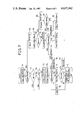
- FIG. 4 is a flowchart showing an embodiment of the fuel supply control method according to the present invention.
- FIGS. 5 and 8 are diagrams showing data maps stored in the ROM
- FIG. 6 is a diagram showing relationship between the engine output power and the air/fuel ratio
- FIGS. 7, 9 and 10 are flowcharts respectively showing operations of the control circuit in other embodiments according to the present invention.
- FIGS. 11 and 12 are diagram showing the constants P HAN and M eHAN .
- FIG. 1 Before entering into the explanation of the preferred embodiment of the invention, reference is first made to FIG. 1 in which the relation between the engine rpm and the absolute pressure P BA within the intake pipe is illustrated.
- the above described process holds true only when the capacity of the intake pipe is small. If the capacity of the intake pipe is large, the absolute pressure P BA and the engine rpm N e deviate from the solid line of FIG. 1. Specifically, if the engine rpm drops, the absolute pressure does not increase immediately. Therefore, the fuel injection time remains unchanged and the engine output torque does not increase enough to resume the engine rpm. Thus, the engine rpm N e further decreases. Thereafter, the absolute pressure P BA increases after a time lag and, in turn, the engine output torque increases to raise the engine rpm N e .
- FIG. 2 is a schematic illustration of an internal combustion engine which is provided with an electronic fuel supply control system operated in accordance with the controlling method according to the present invention.
- the engine designated at 4 is supplied with intake air taken at an air intake port 1 and which passes through an air cleaner 2 and an intake air passage 3.
- a throttle valve 5 is disposed in the intake air passage 3 so that the amount of the air taken into the engine is controlled by the opening degree of the throttle valve 5.
- the engine 4 has an exhaust gas passage 8 with a three-way catalytic converter 9 for promoting the reduction of noxious components such as CO, HC, and NOx in the exhaust gas of the engine.
- a throttle opening sensor 10 consisting of a potentiometer for example, which generates an output signal whose level correspondes to the opening degree of the throttle valve 5.
- an absolute pressure sensor 11 which generates an output signal whose level correspondes to an absolute pressure within the intake air passage 3.
- the engine 4 is also provided with an engine coolant temperature sensor 12 which generates an output signal whose level corresponds to the temperature of the engine coolant, and a crank angle sensor 13 which generates pulse signals in accordance with the rotation of a crankshaft (not illustrated) of the engine.
- the crank angle sensor 13 is for example constructed so that a pulse signal is produced every 120° of revolution of the crankshaft.
- an injector 15 is provided in the intake air passage 3 adjacent to each inlet valve (not shown) of the engine 4.
- Output signals of the throttle opening sensor 10, the absolute pressure sensor 11, the engine coolant temperature sensor 12, the crank angle sensor 13 are connected to a control circuit 16 to which an input terminal of the fuel injector 15 is also connected.
- the control circuit 16 includes a level adjustment circuit 21 for adjusting the level of the output signals of the throttle opening sensor 10, the absolute pressure sensor 11, the coolant temperature sensor 12. These output signals whose level is adjusted by the level adjusting circuit 21 are then applied to an input signal switching circuit 22 in which one of the input signals is selected and in turn outputted to an A/D (Analog to Digital) converter 23 which converts the input signal supplied in analog form to a digital signal.
- the output signal of the crank angle sensor 13 is applied to a waveform shaping circuit 24 which provides a TDC (Top Dead Center) signal according to the output signal of the crank angle sensor 13.
- a counter 25 is provided for measuring the time interval between each pulses of the TDC signal.
- the control circuit 16 further includes a drive circuit 26 for driving the injector 15, a CPU (Central Processing Unit) 27 for performing the arithmetic operation in accordance with programs stored in a ROM (Read Only Memory) 28 also provided in the control circuit 16, and a RAM 29.
- the input signal switching circuit 22, and the A/D converter 23, the counter 25, the drive circuit 26, the CPU 27, the ROM 28, and the RAM 29 are mutually connected by means of an input/output bus 30.
- the CPU 27 reads the above mentioned various information and calculates the fuel injection time duration of the fuel injector 15 corresponding to the amount of fuel to be supplied to the engine 4, using a predetermined calculation formula in accordance with the information read by the CPU 27. During the thus calculated fuel injection time period, the drive circuit 26 actuates the injector 15 so that the fuel is supplied to the engine 4.
- the absolute value of the intake air pressure P BA and the count value M e are read by the CPU 27 respectively as a sampled value P BAn and a sampled value M en , in synchronism with the occurence of every (nth) TDC signal (n being an integer).
- These sampled values P BAn and M en are in turn stored in the RAM 29 at a step 51.
- whether the engine 4 is operating under an idling state or not is detected at a step 52.
- the idling state is detected in terms of the engine coolant temperature T W , the throttle opening degree ⁇ th, and the engine rpm N e derived from the count value M e .
- N e ⁇ N z whether or not the sampled value P BAn is greater than a predetermined value P BO (P BO being about atmospheric pressure value) is detected at a step 54. If P BAn ⁇ P BO , a sampled value P BAn-2 , that is a before preceding sampled value (a value sampled at a sampling time 2 cycles before the latest sampling time), is read out from the RAM 29 at a step 55. Then a subtraction value ⁇ P BA between the latest sampled value P BAn and the sampled value P BAn-2 is calculated at a step 56.
- P BO being about atmospheric pressure value
- the sampled value P BAn of the absolute value of the intake air pressure P BA and the sampled values M en of the count value M e are stored in the RAM 29, for example, for the last six cycles of sampling.
- the subtraction value ⁇ P BA is compared with a predetermined reference value ⁇ P BAGH , corresponding to 64 mmHg for example. If ⁇ P BA ⁇ P BAGH , a multiplication factor ⁇ (for example, 4) is multiplied to the subtraction value ⁇ P BA and the sampled value P BAn is added to the product at a step 58. Thus, the corrected value P BA of the latest sampled value P BAn is calculated. If ⁇ P BA > ⁇ P BAGH , the subtraction value ⁇ P BA is made equal to the predetermined valu ⁇ P BAGH at a step 59 and the program goes to the step 58.
- the corrected value P BA is greater than a predetermined value P BO is detected at a step 60. If P BA ⁇ P BO , the basic fuel injection time T i is determined in accordance with the corrected value P BA , at a step 61, using a data map stored in ROM 28 previously. If P BA >P BO , then the corrected value P BA is made equal to P BO at a step 62 and the program goes to the step 61.
- a sampled value M en-6 of the count value M e which is sampled at a sampling time six cycles before the sampling time of the latest sampled value M en is read out from the RAM 29 at a step 64.
- a subtraction value ⁇ M e between the latest sampled value M en and the sampled value M en-6 is calculated at a step 65.
- whether or not the subtraction value ⁇ M e is smaller than 0 is detected at a step 66. If ⁇ M e ⁇ 0, it indicates that the engine rpm is dropping. Therefore, a correction coefficient ⁇ d corresponding to the latest sampled value M en is looked up, at a step 67, from the data map previously stored in the ROM 28 in such a manner as illustrated in FIG. 5.
- a correction coefficient ⁇ is calculated at a step 68. Then, whether or not this correction coefficient ⁇ is greater than an upper limit value ⁇ GH , is detected at a step 69. If ⁇ > ⁇ GH , then the correction coefficient ⁇ is made equal to the upper limit value ⁇ GH at a step 70. Conversely, if ⁇ GH , the value of the correction coefficient ⁇ is maintained.
- a corrected value P BA of the latest sampled value P BAn is calculated at the step 71 and the basic fuel injection time T i is calculated according to the thus corrected value of P BA at the step 61.
- ⁇ M e ⁇ 0, it indicates that the engine rpm is going up and as in the step 67 mentioned above the correction coefficient ⁇ u corresponding to the latest sampled value M en is looked up from the data map previopusly stored in the ROM 28 as illustrated in FIG. 5 at a step 72. Subsequently, at a step 73, a correction coefficient ⁇ is calculated by multiplying the correction constant ⁇ u to the subtraction value ⁇ M e and adding a value of 1 to the product.
- this correction coefficient ⁇ is smaller than a lower limit value ⁇ GL (0.9 for example) is detected at a step 74. If ⁇ GL , the correction coefficient ⁇ is made equal to the lower limit value ⁇ GL at a step 75. If ⁇ GL , the value of the correction coefficient ⁇ is maintained as it is. Then the calculation operation goes to the step 71 where the correction value P BA of the latest sampled value P BAn is derived.
- the amount of the correction of the sampled value P BAn is determined in proportional to the magnitude of the subtraction value ⁇ M e which corresponds to the variation of the engine rpm.
- the correction constant ⁇ is looked up from a data map of M en - ⁇ d- ⁇ u shown in FIG. 5 since the subtraction value ⁇ M e with respect to the same width ⁇ N e of variation of the engine rpm becomes larger rapidly as the engine rpm becomes lower. Also, for improving the accuracy of the correction value P BA , one of the correction constants ⁇ d and ⁇ u is derived in accordance with the polarity of the subtraction value ⁇ M e . Specifically, when the engine rpm is reducing, the correction constant ⁇ d is looked up from the table and when the engine rpm is increasing, the correction constant ⁇ u which is set to be smaller than ⁇ d is looked up from the table.
- the correction coefficient ⁇ indicates the degree of the shift of the air/fuel ratio towards the rich side or the lean side, of the mixture to be supplied to the engine. Therefore, by providing the upper limit ⁇ GH and the lower limit ⁇ GL for the correction coefficient ⁇ , the correction coefficient ⁇ is controlled within the range where the engine output torgue can be controlled stably by controlling the air/fuel ratio as exemplary shown in FIG. 6. More particularly, if ⁇ > ⁇ GH , the air/fuel ratio becomes over rich so that it gets off from the range and does not control the engine output torque and if ⁇ GL , there is a fear of misfire.
- FIG. 7 shows an operational sequence of another embodiment of the method for controlling the fuel supply according to the present invention.
- the correction coefficient ⁇ 0 and the upper limit value ⁇ M eGH of the subtraction value ⁇ M e corresponding to the latest sampled value M en respectively are looked up from the table stored previously in the ROM 28 as shown in FIG. 8 at a step 76. Then whether or not the subtraction value ⁇ M e is greater than the upper limit value ⁇ M eGH is detected at a step 77. If ⁇ M e > ⁇ M eGH , it indicates that the air/fuel ratio is over rich, then the subtraction value ⁇ M e is made equal to the upper limit value ⁇ M eGH at a step 78.
- the correction value P BA of the latest sampled value P BAn is calculated in such manner that the correction constant ⁇ .sub. 0 is multiplied to the subtraction value ⁇ M e and the latest sampled value P BAn is added to the product at a step 79.
- the correction constant ⁇ 1 and the lower limit value ⁇ M eGL of the subtraction value ⁇ M e corresponding to the latest sampled value M en respectively are looked up, at a step 80, from data map which is previously stored in the ROM 28 in such a manner as illustrated in FIG. 8. Subsequently, whether or not the subtraction value ⁇ M e is smaller than the lower limit value ⁇ M eGL is detected at a step 81.
- the subtraction value ⁇ M e is made equal to the lower limit value ⁇ M eGL at a step 82. This is because otherwise the air/fuel ratio becomes over lean and which in turn causes a misfire. Conversely if ⁇ M e ⁇ M eGL , then the value of the subtraction value ⁇ M e is maintained as it is. Subsequently, the corrected value P BA of the latest sampled value P BAn is calculated at a step 83 in such a manner that the correction constant ⁇ 1 is multiplied to the subtraction value ⁇ M e and the latest sampled value P BAn is added to the product.
- the correction constant ⁇ is determined in accordance with the polarity of the subtraction value ⁇ M e and the value of the latest sampled value M en .
- the upper limit value ⁇ M eGH and the lower limit value ⁇ M eGL are determined in accordance with the polarity of the subtraction value ⁇ M e and the latest sampled value M en .
- FIGS. 9 and 10 illustrate the other embodiment of the method for controlling the fuel suppy according to the present invention.
- the detected value of the pressure within the intake pipe is corrected according to the amount of the variation of the engine rpm. Therefore, the sampled value of the pressure within the intake pipe after the correction varies following the the variation of the engine rpm.
- a relationship between the engine rpm and the absolute pressure within the intake pipe which substantially locates on the curve shown by the solid line in FIG. 1 is obtained.
- the engine operation during such a period as the idling period is stabilized and the driveablilty of the engine is very much improved. This is because the phase delay of the restoring torque of the engine with respect to the change in the engine rpm is reduced even if the capacity of the intake pipe of the engine is relatively large.
Landscapes
- Engineering & Computer Science (AREA)
- Chemical & Material Sciences (AREA)
- Combustion & Propulsion (AREA)
- Mechanical Engineering (AREA)
- General Engineering & Computer Science (AREA)
- Computer Hardware Design (AREA)
- Microelectronics & Electronic Packaging (AREA)
- Electrical Control Of Air Or Fuel Supplied To Internal-Combustion Engine (AREA)
- Measuring Fluid Pressure (AREA)
Applications Claiming Priority (2)
| Application Number | Priority Date | Filing Date | Title |
|---|---|---|---|
| JP59-061648 | 1984-03-29 | ||
| JP59061648A JPS60203832A (ja) | 1984-03-29 | 1984-03-29 | 内燃エンジンの燃料供給制御方法 |
Publications (1)
| Publication Number | Publication Date |
|---|---|
| US4637362A true US4637362A (en) | 1987-01-20 |
Family
ID=13177246
Family Applications (1)
| Application Number | Title | Priority Date | Filing Date |
|---|---|---|---|
| US06/717,117 Expired - Fee Related US4637362A (en) | 1984-03-29 | 1985-03-28 | Method for controlling the supply of fuel for an internal combustion engine |
Country Status (4)
| Country | Link |
|---|---|
| US (1) | US4637362A (de) |
| EP (1) | EP0157340B1 (de) |
| JP (1) | JPS60203832A (de) |
| DE (1) | DE3564984D1 (de) |
Cited By (4)
| Publication number | Priority date | Publication date | Assignee | Title |
|---|---|---|---|---|
| US4700681A (en) * | 1985-04-08 | 1987-10-20 | Toyota Jidosha Kabushiki Kaisha | Fuel injection system for an internal combustion engine |
| US4773373A (en) * | 1985-11-05 | 1988-09-27 | Hitachi, Ltd. | Engine control system |
| US4957083A (en) * | 1987-10-12 | 1990-09-18 | Japan Electronic Control Systems Company, Limited | Fuel supply control system for internal combustion engine with feature providing engine stability in low engine load condition |
| US20040194674A1 (en) * | 2003-04-07 | 2004-10-07 | Del Frari Paul J. | Holding device with demountable panels and shelf |
Families Citing this family (6)
| Publication number | Priority date | Publication date | Assignee | Title |
|---|---|---|---|---|
| JPS60249646A (ja) * | 1984-05-23 | 1985-12-10 | Honda Motor Co Ltd | 内燃エンジンの燃料供給制御方法 |
| JPS60249645A (ja) * | 1984-05-23 | 1985-12-10 | Honda Motor Co Ltd | 内燃エンジンの燃料供給制御方法 |
| JPS6293470A (ja) * | 1985-10-21 | 1987-04-28 | Honda Motor Co Ltd | 内燃エンジンの吸気管内圧検出装置 |
| GB8815930D0 (en) * | 1988-07-05 | 1988-08-10 | Collins Motor Corp Ltd | Fuel metering apparatus |
| US5092301A (en) * | 1990-02-13 | 1992-03-03 | Zenith Fuel Systems, Inc. | Digital fuel control system for small engines |
| DE59103598D1 (de) * | 1990-09-24 | 1995-01-05 | Siemens Ag | Verfahren zur übergangskorrektur der gemischsteuerung bei einer brennkraftmaschine während dynamischen übergangszuständen. |
Citations (8)
| Publication number | Priority date | Publication date | Assignee | Title |
|---|---|---|---|---|
| US4391254A (en) * | 1981-12-11 | 1983-07-05 | Brunswick Corporation | Atomization compensation for electronic fuel injection |
| US4416237A (en) * | 1981-02-26 | 1983-11-22 | Toyota Jidosha Kogyo Kabushiki Kaisha | Method and an apparatus for controlling the air-fuel ratio in an internal combustion engine |
| US4549518A (en) * | 1983-10-20 | 1985-10-29 | Honda Giken Kogyo Kabushiki Kaisha | Method of controlling operating amounts of operation control means for an internal combustion engine |
| US4549516A (en) * | 1983-10-20 | 1985-10-29 | Honda Giken Kogyo Kabushiki Kaisha | Method of controlling operating amounts of operation control means for an internal combustion engine |
| US4562808A (en) * | 1983-09-27 | 1986-01-07 | Mazda Motor Corporation | Engine idling speed control |
| US4580535A (en) * | 1985-06-03 | 1986-04-08 | Mitsubishi Jidosha Kogyo Kabushiki Kaisha | Engine idling speed controlling system |
| US4589279A (en) * | 1984-09-04 | 1986-05-20 | Toyota Jidosha Kabushiki Kaisha | Apparatus and method for detecting intake air mass flow rate |
| US4589390A (en) * | 1984-05-02 | 1986-05-20 | Honda Giken Kogyo K.K. | Air-fuel ratio feedback control method for internal combustion engines |
Family Cites Families (6)
| Publication number | Priority date | Publication date | Assignee | Title |
|---|---|---|---|---|
| US4046129A (en) * | 1970-02-20 | 1977-09-06 | Volkswagenwerk Aktiengesellschaft | Regulating arrangement for internal combustion engines, especially those with a fuel injection system |
| US4010717A (en) * | 1975-02-03 | 1977-03-08 | The Bendix Corporation | Fuel control system having an auxiliary circuit for correcting the signals generated by the pressure sensor during transient operating conditions |
| JPS58122350A (ja) * | 1982-01-13 | 1983-07-21 | Honda Motor Co Ltd | 内燃エンジンのアイドル回転数フィ−ドバック制御装置 |
| JPS58172446A (ja) * | 1982-04-02 | 1983-10-11 | Honda Motor Co Ltd | 内燃機関の作動状態制御装置 |
| FR2527691B1 (fr) * | 1982-05-28 | 1987-12-18 | Honda Motor Co Ltd | Procede permettant de commander les dispositifs de commande de moteurs a combustion interne immediatement apres la fin d'une coupure de carburant |
| JPS60204938A (ja) * | 1984-03-28 | 1985-10-16 | Honda Motor Co Ltd | 内燃エンジンの燃料供給制御方法 |
-
1984
- 1984-03-29 JP JP59061648A patent/JPS60203832A/ja active Pending
-
1985
- 1985-03-26 EP EP85103562A patent/EP0157340B1/de not_active Expired
- 1985-03-26 DE DE8585103562T patent/DE3564984D1/de not_active Expired
- 1985-03-28 US US06/717,117 patent/US4637362A/en not_active Expired - Fee Related
Patent Citations (8)
| Publication number | Priority date | Publication date | Assignee | Title |
|---|---|---|---|---|
| US4416237A (en) * | 1981-02-26 | 1983-11-22 | Toyota Jidosha Kogyo Kabushiki Kaisha | Method and an apparatus for controlling the air-fuel ratio in an internal combustion engine |
| US4391254A (en) * | 1981-12-11 | 1983-07-05 | Brunswick Corporation | Atomization compensation for electronic fuel injection |
| US4562808A (en) * | 1983-09-27 | 1986-01-07 | Mazda Motor Corporation | Engine idling speed control |
| US4549518A (en) * | 1983-10-20 | 1985-10-29 | Honda Giken Kogyo Kabushiki Kaisha | Method of controlling operating amounts of operation control means for an internal combustion engine |
| US4549516A (en) * | 1983-10-20 | 1985-10-29 | Honda Giken Kogyo Kabushiki Kaisha | Method of controlling operating amounts of operation control means for an internal combustion engine |
| US4589390A (en) * | 1984-05-02 | 1986-05-20 | Honda Giken Kogyo K.K. | Air-fuel ratio feedback control method for internal combustion engines |
| US4589279A (en) * | 1984-09-04 | 1986-05-20 | Toyota Jidosha Kabushiki Kaisha | Apparatus and method for detecting intake air mass flow rate |
| US4580535A (en) * | 1985-06-03 | 1986-04-08 | Mitsubishi Jidosha Kogyo Kabushiki Kaisha | Engine idling speed controlling system |
Cited By (4)
| Publication number | Priority date | Publication date | Assignee | Title |
|---|---|---|---|---|
| US4700681A (en) * | 1985-04-08 | 1987-10-20 | Toyota Jidosha Kabushiki Kaisha | Fuel injection system for an internal combustion engine |
| US4773373A (en) * | 1985-11-05 | 1988-09-27 | Hitachi, Ltd. | Engine control system |
| US4957083A (en) * | 1987-10-12 | 1990-09-18 | Japan Electronic Control Systems Company, Limited | Fuel supply control system for internal combustion engine with feature providing engine stability in low engine load condition |
| US20040194674A1 (en) * | 2003-04-07 | 2004-10-07 | Del Frari Paul J. | Holding device with demountable panels and shelf |
Also Published As
| Publication number | Publication date |
|---|---|
| JPS60203832A (ja) | 1985-10-15 |
| EP0157340A3 (en) | 1986-01-15 |
| EP0157340B1 (de) | 1988-09-14 |
| EP0157340A2 (de) | 1985-10-09 |
| DE3564984D1 (en) | 1988-10-20 |
Similar Documents
| Publication | Publication Date | Title |
|---|---|---|
| US4391253A (en) | Electronically controlling, fuel injection method | |
| US4636957A (en) | Method for controlling operating state of an internal combustion engine with an overshoot preventing function | |
| US4442812A (en) | Method and apparatus for controlling internal combustion engines | |
| US5857445A (en) | Engine control device | |
| US4440119A (en) | Electronic fuel injecting method and device for internal combustion engine | |
| US4637362A (en) | Method for controlling the supply of fuel for an internal combustion engine | |
| US4487190A (en) | Electronic fuel injecting method and device for internal combustion engine | |
| US4463732A (en) | Electronic controlled non-synchronous fuel injecting method and device for internal combustion engines | |
| US4667631A (en) | Method and apparatus for controlling air-fuel ratio in internal combustion engine | |
| US4633839A (en) | Method for controlling the supply of fuel for an internal combustion engine | |
| EP0400529B1 (de) | Steuergeräte zur Steuerung des Luftkraftstoffgemisches einer Brennkraftmaschine | |
| EP0166447B1 (de) | Methode und Gerät um das Luft-Kraftstoff-Verhältnis in einer Innenbrennkraftmaschine zu steuern | |
| EP0216111B1 (de) | Kraftstoffeinspritzsystem und Steuerungsverfahren dafür | |
| EP0196227A2 (de) | Steuerungsmethode der Kraftstoffzuspeisung einer Innenbrennkraftmaschine in Beschleunigung | |
| JP3186250B2 (ja) | 内燃機関の空燃比制御装置 | |
| GB2141840A (en) | Fuel injection control method for multi-cylinder internal combustion engines of sequential injection type at acceleration | |
| JP2583662B2 (ja) | エンジンの空燃比制御装置 | |
| US4744345A (en) | Air-fuel ratio feedback control method for internal combustion engines | |
| EP0177297B1 (de) | Kraftstoffversorgungssteuerungsmethode für eine Brennkraftmaschine | |
| US4662339A (en) | Air-fuel ratio control for internal combustion engine | |
| JPH0119057B2 (de) | ||
| US5775295A (en) | Process for controlling a direct-injection internal combustion engine | |
| EP0160949A2 (de) | Verfahren und Gerät zur Steuerung des Luft-Kraftstoffverhältnisses in einer Innenbrennkraftmaschine mit sequentieller Kraftstoffeinspritzung | |
| US4646699A (en) | Method for controlling air/fuel ratio of fuel supply for an internal combustion engine | |
| US4694805A (en) | Air-fuel ratio control method for internal combustion engines |
Legal Events
| Date | Code | Title | Description |
|---|---|---|---|
| AS | Assignment |
Owner name: HONDA GIKEN KOGYO KABUSHIKI KAISHA 27-8, JINGUMAI Free format text: ASSIGNMENT OF ASSIGNORS INTEREST.;ASSIGNORS:YASUOKA, AKIMASA;IWATA, TAKAHIRO;KIUCHI, TAKEO;REEL/FRAME:004388/0901 Effective date: 19850322 |
|
| FEPP | Fee payment procedure |
Free format text: PAYOR NUMBER ASSIGNED (ORIGINAL EVENT CODE: ASPN); ENTITY STATUS OF PATENT OWNER: LARGE ENTITY |
|
| FPAY | Fee payment |
Year of fee payment: 4 |
|
| FPAY | Fee payment |
Year of fee payment: 8 |
|
| REMI | Maintenance fee reminder mailed | ||
| LAPS | Lapse for failure to pay maintenance fees | ||
| FP | Lapsed due to failure to pay maintenance fee |
Effective date: 19990120 |
|
| STCH | Information on status: patent discontinuation |
Free format text: PATENT EXPIRED DUE TO NONPAYMENT OF MAINTENANCE FEES UNDER 37 CFR 1.362 |