US4641496A - Continuous rotary regeneration system for a particulate trap - Google Patents
Continuous rotary regeneration system for a particulate trap Download PDFInfo
- Publication number
- US4641496A US4641496A US06/682,523 US68252384A US4641496A US 4641496 A US4641496 A US 4641496A US 68252384 A US68252384 A US 68252384A US 4641496 A US4641496 A US 4641496A
- Authority
- US
- United States
- Prior art keywords
- trap
- shield
- flow
- entrance face
- particulates
- Prior art date
- Legal status (The legal status is an assumption and is not a legal conclusion. Google has not performed a legal analysis and makes no representation as to the accuracy of the status listed.)
- Expired - Lifetime
Links
Images

Classifications
-
- F—MECHANICAL ENGINEERING; LIGHTING; HEATING; WEAPONS; BLASTING
- F01—MACHINES OR ENGINES IN GENERAL; ENGINE PLANTS IN GENERAL; STEAM ENGINES
- F01N—GAS-FLOW SILENCERS OR EXHAUST APPARATUS FOR MACHINES OR ENGINES IN GENERAL; GAS-FLOW SILENCERS OR EXHAUST APPARATUS FOR INTERNAL-COMBUSTION ENGINES
- F01N3/00—Exhaust or silencing apparatus having means for purifying, rendering innocuous, or otherwise treating exhaust
- F01N3/02—Exhaust or silencing apparatus having means for purifying, rendering innocuous, or otherwise treating exhaust for cooling, or for removing solid constituents of, exhaust
- F01N3/021—Exhaust or silencing apparatus having means for purifying, rendering innocuous, or otherwise treating exhaust for cooling, or for removing solid constituents of, exhaust by means of filters
- F01N3/023—Exhaust or silencing apparatus having means for purifying, rendering innocuous, or otherwise treating exhaust for cooling, or for removing solid constituents of, exhaust by means of filters using means for regenerating the filters, e.g. by burning trapped particles
- F01N3/027—Exhaust or silencing apparatus having means for purifying, rendering innocuous, or otherwise treating exhaust for cooling, or for removing solid constituents of, exhaust by means of filters using means for regenerating the filters, e.g. by burning trapped particles using electric or magnetic heating means
-
- Y—GENERAL TAGGING OF NEW TECHNOLOGICAL DEVELOPMENTS; GENERAL TAGGING OF CROSS-SECTIONAL TECHNOLOGIES SPANNING OVER SEVERAL SECTIONS OF THE IPC; TECHNICAL SUBJECTS COVERED BY FORMER USPC CROSS-REFERENCE ART COLLECTIONS [XRACs] AND DIGESTS
- Y10—TECHNICAL SUBJECTS COVERED BY FORMER USPC
- Y10S—TECHNICAL SUBJECTS COVERED BY FORMER USPC CROSS-REFERENCE ART COLLECTIONS [XRACs] AND DIGESTS
- Y10S55/00—Gas separation
- Y10S55/30—Exhaust treatment
Definitions
- This invention is directed to electrical regeneration systems for particulate traps used with diesel type engines and, more particularly, to an apparatus and method which permits such electrical regeneration system to operate on a continuous basis and yet be more economical, less complex, and more reliable.
- Regeneration systems for particulate traps for diesel engines have typically employed an auxiliary fuel burner unit which elevated the temperature of gases flowing through the trap to bring about carbon ignition and oxidation.
- One type is based upon the concept of bypassing exhaust gases during the regeneration cycle so that the filter or trap portion from which the exhaust gases have been removed can then be heated to an oxidation temperature for removing the particulates.
- the total apparatus assembly usually requires a sizable number of components, including a trap (such as a ceramic honeycomb with alternately blocked channels), bypass valve and channel apparatus, a fuel pump and associated nozzle for delivering a well-atomized fuel spray, an air pump for supplying combustion air, ignition means for igniting the combustible fuel/air mixture for additional heat content to the exhaust flow, a control system to detect when to initiate regeneration based on the ratio of trap back-pressure to the clean trap back-pressure, and a control system to sequence the bypass of the exhaust flow, initiate heating, and turn off the ignition system when the regeneration is complete.
- a trap such as a ceramic honeycomb with alternately blocked channels
- bypass valve and channel apparatus for delivering a well-atomized fuel spray
- a fuel pump and associated nozzle for delivering a well-atomized fuel spray
- an air pump for supplying combustion air
- ignition means for igniting the combustible fuel/air mixture for additional heat content to the exhaust flow
- a control system to detect when to
- This apparatus is complex and expensive because of the number of elements that make up the assembly.
- the controls to detect when to initiate the regeneration and the controls to sequence the bypass of the exhaust valve, as well as the fuel pump, air pump, and the bypass valve and channel structure are all rather expensive and complex items which place a heavy burden on the designer to assure reliability.
- Another type of electric regeneration system is of the shifting heater type where a unitary filter trap is progressively and sequentially cleansed by either rotating an electrical heating element across the face of the filter, as shown in U.S Pat. No. 4,359,864, or the electrical heating elements are embedded in the ceramic filter itself and are sequentially energized to carry out a movable heating of different sections of the filter while a movable shield is carried across the face of the filter to block off exhaust flow in that portion of the filter in which the electrical elements have been energized, as shown in U.S. Pat. No. 4,276,066.
- U.S. Pat. No. 4,359,864 is disadvantageous because it requires a full flow of exhaust gas through the entire filter at all times, and because the electrical heating element configuration, shaped as a rod which is rotationally scanned across the face of the filter element, much like the hand of a clock, has inadequate contact with the total gas flowing therethrough.
- the amount of electrical power required for such heating element must be great enough to heat the large exhaust gas flow which is passing thereacross and to raise such exhaust gas flow to a substantial temperature level permitting ignition of the particulates.
- This is a particularly inefficient method for bringing about the ignition of particulates since it is the temperature of the flow through the filter which brings about the ignition, such flow receiving its heat content from the electrical heating element.
- this patent demonstrates a disclosure which is not feasible because the electrical resistance heater must heat the total exhaust flow, which requires more energy than can be generated in conventional on-board resistance heater elements.
- the heating elements are embedded in the ceramic filter trap and encounter the problem of the thermal expansion of the heating element in the ceramic in the trap tending to crack the ceramic. With a cracked ceramic matrix, the trapping efficiency of the trap drops to very low levels.
- the resistance heater must be the sole mechanism for carrying out ignition of each and every particulate, since all exhaust flow through the energized elements is blocked off during such regeneration.
- the invention is an apparatus and method for continuously regenerating a particulate filter trap for an internal combustion engine.
- the apparatus has means for normally conducting the exhaust gas of the engine to and through the trap, the trap having a plurality of generally aligned flow channels extending from the entrance face of the trap.
- the apparatus particularly comprises: (a) movable means effective to shield a segment of the trap entrance face from the full flow of exhaust gas while permitting a portion of the exhaust gas flow to bleed therethrough; (b) electrical resistance heating means having a movable heating element carried by the shield and interposed between the trap face and the shield; and (c) means for substantially continuously moving the shield and element conjointly across the trap face to ignite one or more columns of the particulates in the trap aligned with the shield and element, the ignited particles and bleed flow causing the oxidation to proceed throughout the extent of the columns of particulates without need for additional exterior heat.
- the particulate trap is constructed as a cylinder with its face formed as a circle, the shield being constituted as a sector of the circle effective to rotate about the face of the trap utilizing the apex of the sector as the axis of rotation.
- the shield is a 60° sector moved in a full 360° rotational scan.
- the bleed flow is provided by the presence of bleed holes in the shield spaced uniformly across the shield sufficient to provide a bleed flow rate of about 0.12 lb/min.
- the shield segment is moved across the face of the trap at a slow speed of about one revolution in 30 minutes.
- the heating element is sized to heat the bleed flow to a temperature of at least 1000° F. and optimally to 1200° F., utilizing a power source of only about 500 watts.
- the method of regenerating the particulate trap comprises: (a) slowly and conjointly moving a segmental shield and electrical heating element across the entrance face, while heating the shielded portion of the entrance face to a particulate ignition temperature, the segmental shield blocking off the full flow of the exhaust gases from the portion of the entrance face covered by the shield, while permitting a portion of the exhaust gases to bleed therethrough; and (b) controlling the movement of the shield and element to allow the heated bleed gas to ignite one or more columns of particulates in the trap aligned with the shield and element and to support oxidation of the particulates substantially along the entire length of the columns.
- the heating element and shield conform in configuration to a sector of a circle; the shield and element are rotated about the apex of such sector, the rotary movement being at a speed of about one revolution per 30 minutes.
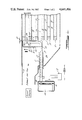
- FIG. 1 is a central sectional elevational view of a portion of the particulate trap and of an assembly for the rotary regenerator of this invention
- FIG. 2 is a sectional view of a portion of the illustration in FIG. 1 taken in the direction of lines 2--2 indicated 1;
- FIG. 3 is an end elevational view of the entrance face to the trap, taken substantially along lines 3--3 of FIG. 2.
- the apparatus comprises essentially a trap A, an exhaust flow shielding means B, an electric heating means C, a continuous mover means D, and a power supply and control E.
- the regenerative apparatus and system of this invention are adapted for use with an automotive internal combustion engine, such as a diesel engine, that emits carbon particulates by way of the exhaust gas flow therefrom.
- the exhaust gas is channeled by walls 10 from the engine to the on-board trap A which collects particulates at a rate and in a quantity much greater than can be held by the trap over its life without regeneration; thus, the trap A must be cleansed periodically through a regenerative cycle or system.
- the trap is here cylindrically shaped, having a cylindrical axis 11 with the exhaust gas flow flowing along the axis therethrough after having entered through a circular face 12 of the trap at one end thereof.
- the trap has a filter element 13 operative to filter out and collect a substantial portion of the entrained particulates in the exhaust gas that is permitted to flow therethrough.
- the filter element may preferably be comprised of a rigid or fibrous ceramic such as aluminum silicate or mullite aluminum titanate or cordierite. In any case, the ceramic material is formed in a honeycomb structure with alternately blocked straight channels in a well known manner (see reference SAE 810114).
- the filter is encased in a housing 10, all of the walls being preferably formed of stainless steel.
- the mode of entrapment of such honeycomb ceramic filter is by way of interception; particulates larger than approximately the mean pore size of the ceramic material are intercepted and prevented from passing through the ceramic.
- the ceramic is preferably formed in parallel channels 14-15 which extend substantially throughout the length of the ceramic filter parallel to the axis of such trap. Alternate channels are plugged (at 15) at the frontal face of the filter element, and the unplugged channels 14 are then plugged at the trailing end of each of the channels. In this manner exhaust flow entering the unplugged channels 1 through the frontal face 12 of the filter must pass through the porous walls 17 of such elongated channels to enter a channel 16 which has an exit opening at the trailing end of the trap.
- the movable means B effective to shield a segment of the trap entrance face 12, comprises a metallic cover 18, which in an elevational view is pie-shape, to occupy a sector of a circle of approximately 60° (45°-75°), such as shown in FIG. 3.
- the cover has side walls 20 which extend toward the filter element to be juxtaposed with a space 21 therebetween of less than 0.010 inch to minimize leakage.
- the cover 18 is attached at its center or apex 22 to a tube 23 which extends normal to the plane of the cover and face 12, the tube 23 extends through and outwardly from the plenum chamber 24 (leading the exhaust gases to the filter element).
- the exhaust flow from the engine is carried by way of walls 10 and the plenum chamber to the frontal face 12 of the filter element; normally such flow would be permitted to enter all of the available entrance channels 14 of the filter element.
- the shield means B blocks off such full flow of exhaust gases from those channels 14 (and the columns of particulates 25 associated with the walls of such channels) which are aligned with the cover (when the cover is projected onto the face of the filter element as viewed along an axial direction, as shown in FIG. 3).
- Small bleed holes 26 are formed in the cover of the shield means so as to allow a bleeding of a small portion of the exhaust gas therethrough.
- Such holes are preferably sized to have a diameter of about 0.050 inch and are used in a number, such as approximately 9, distributed evenly across such cover.
- the normal exhaust gas flow for a 2.3 L diesel engine at 2500 rpm will be about 7.6 lb/min, and the bleed flow will be reduced substantially to an amount of about 0.12 lb/min.
- the electrical heater C comprises a wire heating element 30 which continuously extends as a resistance strand from a central shaft portion 31 passing through the apex 22 of the shield and extends radially outwardly at 32 to return along a serpentine configuration portion 33 extending radially inwardly to terminate adjacent the apex 22.
- the configuration occupies a substantial projected area of the cover.
- the heating element 30 is interposed between the cover 18 and the filter element 13; the element 30 has one side spaced from the filter entrance face a distance 34 of less than 0.080 inch.
- the heating element consists of a nichrome resistance element contained in magnesium oxide powder insulation with a 0.260 in diameter stainless steel sheath; the heating element is typically supplied with about 500 watts (300-800 watts) to elevate the temperature of the bleed gases passing thereacross to a temperature of at least 1000° F. and preferably to at least about 1200° F.
- the central shaft portion 31 of the heating element is journalled in the tube 23 of the shielding means in a manner so as to be conjointly carried therewith as the cover is rotated.
- Electrical lead wires 35 are connected to the central shaft portion 31 of the heating element 30 and extend outwardly from such tube through slip rings providing a connection to a power supply and control E, remote from the heating element.
- the continuous mover means D rotationally actuates the cover and heating element assembly
- means D comprises a spur gear 40 connected to one end of the tube 23 of the shield means and shaft portion 31 of the heater means, so as to drive such tube 23, shield 18 and element 30 rotationally.
- a reduction gear 41 is meshed with the spur gear and is drivingly connected to an electrical motor 42, as shown in FIG. 1.
- the reduction gear is selected so as to provide a rotational movement of the shield means tube of about one revolution per 30 minutes. This provides five minutes of heating time for each channel which is necessary to initiate regeneration.
- a reduced rotational speed may be required to provide an adequate level of particulates to ensure self-sustaining regeneration in each channel.
- the control E is comprised a simple bi-metallic thermostat 44 stationed at a position between the electrical heating element and the entrance face 12 of the filter element.
- the thermostat is used as a control to prevent overheating of the electric resistance elements.
- the thermostat is of the slow response type, which is adequate for a continuously heated system such as illustrated herein. This slow response thermostat does not require heat up periodically as in prior art systems.
- the method of this invention for regenerating a particulate trap and the operation of the apparatus herein is as follows: (a) slowly and conjointly moving a segmental shield and an electrical heating element across the entrance face of the trap while heating the shielded portion of the entrance face to a particulate ignition temperature, the segmental shield blocking off the full flow of the exhaust gases from the portion of the entrance face covered by the shield while permitting a sequestered portion of the flow to bleed through the shield and across the heating element; and (b) controlling the movement of the shield and element to allow the heated bleed gas to ignite one or more columns of particulates in the trap aligned with the shield and element to support oxidation of the particulates substantially along the entire length of the columns.
- the bleed gas and a segment of the entrance face 12, as covered or scanned by the electrical heating element, will be heated to a temperature of about 1200° F.
- the power requirement for carrying this out will be about 500 watts. This is based on data from previous systems which required 3000 watts to heat the entire inlet face of the trap.
- the 60° segment of the entrance face will only require one-sixth of such 3000 watts or approximately 500.
- the six-fold reduction in electrical power requirement has a major advantage in reducing the alternator power requirement for the regenerator system.
- Particulate oxidation is, of course, initiated by the electrically heated bleed gases flowing thereover, but continued oxidation of the particulate columns is supported simply by further bleed gases or exhaust gases supplying the necessary oxygen to support combustion; additional input heat is not necessary.
- the unshielded portion of the trap filter is a bypass; that is, the full flow of exhaust gas is prevented from flowing through such covered segment and is forced to bypass therearound.
- the necessity for complex channeling structures is eliminated and the system is continuous. After the shield and electrical element has rotated a full 360°, it is ready to be rotated continuously again so that the trap filter is continuously regenerated at intervals depending upon the completion of one rotation of such elements.
- This system eliminates the need for many of the components required in previous prior art electrical regenerations systems, such as: a bypass valve, bypass channel, air pump, 83% of the electrical heating wire is not needed, a sophisticated fast response temperature control, a back pressure sensing system, and dual controls for initiating sequencing of the regeneration. As a result, the system is considerably more economical, less complex, and more reliable in operation to carry out regeneration over the life of the vehicle.
Landscapes
- Engineering & Computer Science (AREA)
- Chemical & Material Sciences (AREA)
- Combustion & Propulsion (AREA)
- Mechanical Engineering (AREA)
- General Engineering & Computer Science (AREA)
- Processes For Solid Components From Exhaust (AREA)
- Exhaust Gas Treatment By Means Of Catalyst (AREA)
Priority Applications (5)
| Application Number | Priority Date | Filing Date | Title |
|---|---|---|---|
| US06/682,523 US4641496A (en) | 1984-12-17 | 1984-12-17 | Continuous rotary regeneration system for a particulate trap |
| CA000495934A CA1244356A (en) | 1984-12-17 | 1985-11-21 | Continuous rotary regeneration system for a particulate trap |
| DE8585308463T DE3569404D1 (en) | 1984-12-17 | 1985-11-21 | Continuous rotary regeneration system for a particulate trap |
| EP85308463A EP0188075B1 (de) | 1984-12-17 | 1985-11-21 | Kontinuierlich drehendes Regenerierungssystem für Partikelfilter |
| JP60279428A JPS61145312A (ja) | 1984-12-17 | 1985-12-13 | 粒子トラツプ用連続回転式再生装置 |
Applications Claiming Priority (1)
| Application Number | Priority Date | Filing Date | Title |
|---|---|---|---|
| US06/682,523 US4641496A (en) | 1984-12-17 | 1984-12-17 | Continuous rotary regeneration system for a particulate trap |
Publications (1)
| Publication Number | Publication Date |
|---|---|
| US4641496A true US4641496A (en) | 1987-02-10 |
Family
ID=24740076
Family Applications (1)
| Application Number | Title | Priority Date | Filing Date |
|---|---|---|---|
| US06/682,523 Expired - Lifetime US4641496A (en) | 1984-12-17 | 1984-12-17 | Continuous rotary regeneration system for a particulate trap |
Country Status (5)
| Country | Link |
|---|---|
| US (1) | US4641496A (de) |
| EP (1) | EP0188075B1 (de) |
| JP (1) | JPS61145312A (de) |
| CA (1) | CA1244356A (de) |
| DE (1) | DE3569404D1 (de) |
Cited By (26)
| Publication number | Priority date | Publication date | Assignee | Title |
|---|---|---|---|---|
| US4730454A (en) * | 1985-10-26 | 1988-03-15 | FEV Forschungsgesellschaft fur Energie-Technik und Verbrennungsmotoren mbH | Process and system for the oxidation of engine emission particulates deposited in a particulate filter trap |
| DE8801474U1 (de) * | 1988-02-05 | 1989-06-22 | Huss Maschinenfabrik GmbH & Co KG, 2800 Bremen | Regenerierbarer Rußfilter für das Abgas von Verbrennungsmotoren |
| US4867768A (en) * | 1987-08-21 | 1989-09-19 | Donaldson Company, Inc. | Muffler apparatus with filter trap and method of use |
| DE3808075A1 (de) * | 1988-03-11 | 1989-09-21 | Rohs Ulrich | Mechanische russfiltervorrichtung |
| US4878928A (en) * | 1988-07-28 | 1989-11-07 | Donaldson Company, Inc. | Apparatus for increasing regenerative filter heating element temperature |
| US4899540A (en) * | 1987-08-21 | 1990-02-13 | Donaldson Company, Inc. | Muffler apparatus with filter trap and method of use |
| US4902309A (en) * | 1987-06-24 | 1990-02-20 | Hempenstall George T | Improved method for the ignition and combustion of particulates in diesel exhaust gases |
| US4925463A (en) * | 1986-05-30 | 1990-05-15 | Dieter Kuhnert | Exhaust gas cleaning system for diesel engines |
| US5024054A (en) * | 1989-12-26 | 1991-06-18 | Donaldson Company, Inc. | Engine exhaust system with sequential loading of multiple filters |
| US5065574A (en) * | 1990-05-29 | 1991-11-19 | Caterpillar Inc. | Particulate trap regeneration apparatus and method |
| US5212948A (en) * | 1990-09-27 | 1993-05-25 | Donaldson Company, Inc. | Trap apparatus with bypass |
| US5250094A (en) | 1992-03-16 | 1993-10-05 | Donaldson Company, Inc. | Ceramic filter construction and method |
| US5293742A (en) * | 1991-06-27 | 1994-03-15 | Donaldson Company, Inc. | Trap apparatus with tubular filter element |
| WO2003004134A3 (de) * | 2001-06-30 | 2003-04-17 | Gerd Gaiser | Verfahren zur reinigung von abgasen |
| WO2002102493A3 (de) * | 2001-06-18 | 2003-05-01 | Hjs Fahrzeugtechnik Gmbh & Co | Mit russabbrennung arbeitender partikelfilter für dieselmotoren |
| US6631612B1 (en) * | 1999-12-17 | 2003-10-14 | Mitsubishi Heavy Industries, Ltd. | Device for eliminating particulates in exhaust gas and method for eliminating the particulates |
| US20040103788A1 (en) * | 2002-08-23 | 2004-06-03 | Michael Streichsbier | Apparatus for cleaning a diesel particulate filter with multiple filtration stages |
| US20040226287A1 (en) * | 2003-02-18 | 2004-11-18 | Edgar Bradley L. | Automated regeneration apparatus and method for a particulate filter |
| DE102004001571A1 (de) * | 2004-01-08 | 2005-08-04 | Alfred Neitz | Verfahren und Vorrichtung zur Regeneration eines Partikelfilters |
| US20050193961A1 (en) * | 2002-10-16 | 2005-09-08 | Guinther Gregory H. | Emissions control system for diesel fuel combustion after treatment system |
| US20060191246A1 (en) * | 2005-02-28 | 2006-08-31 | Caterpillar Inc. | Filter service system and method |
| US20070187314A1 (en) * | 2004-03-23 | 2007-08-16 | Dytech Corporation Limited | Chemical reaction |
| US20100205943A1 (en) * | 2009-02-18 | 2010-08-19 | Gm Global Technology Operations, Inc. | Electrically heated particulate filter zone-based post fuel injection system |
| US20130031894A1 (en) * | 2010-04-07 | 2013-02-07 | Emitec Gesellschaft Fuer Emissionstechnologie Mbh | Method and exhaust-gas treatment device for regenerating an exhaust-gas purification component and motor vehicle having the exhaust-gas treatment device |
| US20140352565A1 (en) * | 2009-05-08 | 2014-12-04 | Rheinmetall Waffe Munition Gmbh | Activation unit for explosive masses or explosive bodies |
| WO2018073080A1 (de) * | 2016-10-18 | 2018-04-26 | Hug Engineering Ag | Russpartikelfilter und verfahren zum betreiben eines russpartikelfilters |
Families Citing this family (6)
| Publication number | Priority date | Publication date | Assignee | Title |
|---|---|---|---|---|
| DE8816514U1 (de) * | 1988-04-25 | 1989-10-26 | Emitec Gesellschaft für Emissionstechnologie mbH, 5204 Lohmar | Elektrisch beheizbarer Katalysator-Trägerkörper |
| EP0469237A1 (de) * | 1990-08-03 | 1992-02-05 | STROMERZEUGUNG GmbH & CO. ANLAGENBAU KG | Verfahren und Vorrichtung zum Umwandeln von Molekülen in einer Fluidströmung |
| DE4138284A1 (de) * | 1991-11-21 | 1993-05-27 | Kloeckner Humboldt Deutz Ag | Vorrichtung zur reinigung von dieselmotorabgasen |
| DE102008063809B4 (de) * | 2008-12-19 | 2011-05-12 | Hjs Emission Technology Gmbh & Co. Kg | Abgasreinigungsanlage sowie Verfahren zum Betrieb einer Abgasreinigungsanlage |
| JP7219086B2 (ja) * | 2018-12-27 | 2023-02-07 | オムロンヘルスケア株式会社 | 血圧計、血圧測定方法、およびプログラム |
| CN112796856B (zh) * | 2021-02-23 | 2024-07-16 | 北京高鑫伟业科技有限公司 | 一种新型电加热柴油颗粒捕集器后处理器 |
Citations (4)
| Publication number | Priority date | Publication date | Assignee | Title |
|---|---|---|---|---|
| US4276066A (en) * | 1980-02-25 | 1981-06-30 | General Motors Corporation | Monolith diesel exhaust filter with self-regeneration |
| US4359864A (en) * | 1981-02-05 | 1982-11-23 | Caterpillar Tractor Co. | Burn-out type cleaning means for particulate filter of engine exhaust system |
| US4427418A (en) * | 1981-03-16 | 1984-01-24 | Kabushiki Kaisha Toyota Chuo Kenkyusho | Device for collecting particulates in exhaust gases |
| US4481767A (en) * | 1983-07-08 | 1984-11-13 | General Motors Corporation | Diesel exhaust cleaner and burner system with flame distributor |
Family Cites Families (2)
| Publication number | Priority date | Publication date | Assignee | Title |
|---|---|---|---|---|
| JPS57171015A (en) * | 1981-04-15 | 1982-10-21 | Nippon Denso Co Ltd | Particle collector |
| JPS5876122A (ja) * | 1981-10-30 | 1983-05-09 | Nippon Denso Co Ltd | 微粒子捕集装置 |
-
1984
- 1984-12-17 US US06/682,523 patent/US4641496A/en not_active Expired - Lifetime
-
1985
- 1985-11-21 CA CA000495934A patent/CA1244356A/en not_active Expired
- 1985-11-21 EP EP85308463A patent/EP0188075B1/de not_active Expired
- 1985-11-21 DE DE8585308463T patent/DE3569404D1/de not_active Expired
- 1985-12-13 JP JP60279428A patent/JPS61145312A/ja active Pending
Patent Citations (4)
| Publication number | Priority date | Publication date | Assignee | Title |
|---|---|---|---|---|
| US4276066A (en) * | 1980-02-25 | 1981-06-30 | General Motors Corporation | Monolith diesel exhaust filter with self-regeneration |
| US4359864A (en) * | 1981-02-05 | 1982-11-23 | Caterpillar Tractor Co. | Burn-out type cleaning means for particulate filter of engine exhaust system |
| US4427418A (en) * | 1981-03-16 | 1984-01-24 | Kabushiki Kaisha Toyota Chuo Kenkyusho | Device for collecting particulates in exhaust gases |
| US4481767A (en) * | 1983-07-08 | 1984-11-13 | General Motors Corporation | Diesel exhaust cleaner and burner system with flame distributor |
Cited By (37)
| Publication number | Priority date | Publication date | Assignee | Title |
|---|---|---|---|---|
| US4730454A (en) * | 1985-10-26 | 1988-03-15 | FEV Forschungsgesellschaft fur Energie-Technik und Verbrennungsmotoren mbH | Process and system for the oxidation of engine emission particulates deposited in a particulate filter trap |
| US4925463A (en) * | 1986-05-30 | 1990-05-15 | Dieter Kuhnert | Exhaust gas cleaning system for diesel engines |
| US4902309A (en) * | 1987-06-24 | 1990-02-20 | Hempenstall George T | Improved method for the ignition and combustion of particulates in diesel exhaust gases |
| US4867768A (en) * | 1987-08-21 | 1989-09-19 | Donaldson Company, Inc. | Muffler apparatus with filter trap and method of use |
| US4899540A (en) * | 1987-08-21 | 1990-02-13 | Donaldson Company, Inc. | Muffler apparatus with filter trap and method of use |
| DE8801474U1 (de) * | 1988-02-05 | 1989-06-22 | Huss Maschinenfabrik GmbH & Co KG, 2800 Bremen | Regenerierbarer Rußfilter für das Abgas von Verbrennungsmotoren |
| EP0326659B1 (de) * | 1988-02-05 | 1991-02-06 | Huss Maschinenfabrik GmbH & Co. KG | Regenerierbarer Russfilter für das Abgas von Verbrennungsmotoren |
| DE3808075A1 (de) * | 1988-03-11 | 1989-09-21 | Rohs Ulrich | Mechanische russfiltervorrichtung |
| US4878928A (en) * | 1988-07-28 | 1989-11-07 | Donaldson Company, Inc. | Apparatus for increasing regenerative filter heating element temperature |
| US5024054A (en) * | 1989-12-26 | 1991-06-18 | Donaldson Company, Inc. | Engine exhaust system with sequential loading of multiple filters |
| US5065574A (en) * | 1990-05-29 | 1991-11-19 | Caterpillar Inc. | Particulate trap regeneration apparatus and method |
| WO1991019080A1 (en) * | 1990-05-29 | 1991-12-12 | Caterpillar Inc. | Particulate trap regeneration apparatus and method |
| US5212948A (en) * | 1990-09-27 | 1993-05-25 | Donaldson Company, Inc. | Trap apparatus with bypass |
| US5293742A (en) * | 1991-06-27 | 1994-03-15 | Donaldson Company, Inc. | Trap apparatus with tubular filter element |
| US5250094A (en) | 1992-03-16 | 1993-10-05 | Donaldson Company, Inc. | Ceramic filter construction and method |
| US6631612B1 (en) * | 1999-12-17 | 2003-10-14 | Mitsubishi Heavy Industries, Ltd. | Device for eliminating particulates in exhaust gas and method for eliminating the particulates |
| WO2002102493A3 (de) * | 2001-06-18 | 2003-05-01 | Hjs Fahrzeugtechnik Gmbh & Co | Mit russabbrennung arbeitender partikelfilter für dieselmotoren |
| US7029510B2 (en) | 2001-06-18 | 2006-04-18 | Hjs Fahrzeugtechnik Gmbh & Co. | Particle filter with carbon deposit combustion for diesel engines |
| US20040128960A1 (en) * | 2001-06-18 | 2004-07-08 | Frankle Gerhard Jurgen | Particle filter with carbon deposit combustion for diesel engines |
| WO2003004134A3 (de) * | 2001-06-30 | 2003-04-17 | Gerd Gaiser | Verfahren zur reinigung von abgasen |
| US20040103788A1 (en) * | 2002-08-23 | 2004-06-03 | Michael Streichsbier | Apparatus for cleaning a diesel particulate filter with multiple filtration stages |
| US7025811B2 (en) | 2002-08-23 | 2006-04-11 | Cleaire Advanced Emission Controls | Apparatus for cleaning a diesel particulate filter with multiple filtration stages |
| US8006652B2 (en) * | 2002-10-16 | 2011-08-30 | Afton Chemical Intangibles Llc | Emissions control system for diesel fuel combustion after treatment system |
| US20050193961A1 (en) * | 2002-10-16 | 2005-09-08 | Guinther Gregory H. | Emissions control system for diesel fuel combustion after treatment system |
| US20040226287A1 (en) * | 2003-02-18 | 2004-11-18 | Edgar Bradley L. | Automated regeneration apparatus and method for a particulate filter |
| DE102004001571B4 (de) * | 2004-01-08 | 2006-04-06 | Alfred Neitz | Vorrichtung zur Regeneration eines Partikelfilters |
| DE102004001571A1 (de) * | 2004-01-08 | 2005-08-04 | Alfred Neitz | Verfahren und Vorrichtung zur Regeneration eines Partikelfilters |
| US20070187314A1 (en) * | 2004-03-23 | 2007-08-16 | Dytech Corporation Limited | Chemical reaction |
| US20060191246A1 (en) * | 2005-02-28 | 2006-08-31 | Caterpillar Inc. | Filter service system and method |
| US7410521B2 (en) * | 2005-02-28 | 2008-08-12 | Caterpillar Inc. | Filter service system and method |
| US20100205943A1 (en) * | 2009-02-18 | 2010-08-19 | Gm Global Technology Operations, Inc. | Electrically heated particulate filter zone-based post fuel injection system |
| US8051644B2 (en) * | 2009-02-18 | 2011-11-08 | GM Global Technology Operations LLC | Electrically heated particulate filter zone-based post fuel injection system |
| US20140352565A1 (en) * | 2009-05-08 | 2014-12-04 | Rheinmetall Waffe Munition Gmbh | Activation unit for explosive masses or explosive bodies |
| US20130031894A1 (en) * | 2010-04-07 | 2013-02-07 | Emitec Gesellschaft Fuer Emissionstechnologie Mbh | Method and exhaust-gas treatment device for regenerating an exhaust-gas purification component and motor vehicle having the exhaust-gas treatment device |
| US9518493B2 (en) * | 2010-04-07 | 2016-12-13 | Emitec Gesellschaft Fuer Emissionstechnologie Mbh | Method and exhaust-gas treatment device for regenerating an exhaust-gas purification component and motor vehicle having the exhaust-gas treatment device |
| WO2018073080A1 (de) * | 2016-10-18 | 2018-04-26 | Hug Engineering Ag | Russpartikelfilter und verfahren zum betreiben eines russpartikelfilters |
| US10960337B2 (en) | 2016-10-18 | 2021-03-30 | Hug Engineering Ag | Soot particle filter and method for operating a soot particle filter |
Also Published As
| Publication number | Publication date |
|---|---|
| EP0188075B1 (de) | 1989-04-12 |
| CA1244356A (en) | 1988-11-08 |
| DE3569404D1 (en) | 1989-05-18 |
| JPS61145312A (ja) | 1986-07-03 |
| EP0188075A1 (de) | 1986-07-23 |
Similar Documents
| Publication | Publication Date | Title |
|---|---|---|
| EP0188075B1 (de) | Kontinuierlich drehendes Regenerierungssystem für Partikelfilter | |
| US4544388A (en) | Apparatus for periodically oxidizing particulates collected from exhaust gases | |
| AU638756B2 (en) | Particulate trap regeneration apparatus and method | |
| US5042249A (en) | Soot filter for cleaning the exhaust from an internal combustion engine | |
| EP0244061B1 (de) | Einrichtung zur Beseitigung von partikelförmigem Material aus einem Gas | |
| US4276066A (en) | Monolith diesel exhaust filter with self-regeneration | |
| US4562695A (en) | Particulate trap system for engine exhaust using electrically powered regeneration | |
| EP0266932B1 (de) | Elektrisches Zündsystem für die Regenerierung eines Partikelfilters | |
| US4481767A (en) | Diesel exhaust cleaner and burner system with flame distributor | |
| EP0608619B1 (de) | Abgasreinigung | |
| EP0742352A2 (de) | Partikelfiltereinrichtung eines Dieselmotors | |
| JPS58210310A (ja) | 内燃機関のカ−ボン微粒子浄化装置 | |
| US4503672A (en) | Diesel exhaust cleaner with glow plug igniters and flow limiting valve | |
| US4494375A (en) | Filtration system for diesel engine exhaust-I | |
| US4054417A (en) | Regenerative-filter-incinerator device | |
| CN101415915B (zh) | 用于操作减排系统的方法和设备 | |
| CA1216200A (en) | Method for operating a regenerative diesel engine particulate trap | |
| JPH08312333A (ja) | 排ガス浄化装置 | |
| EP0167527B1 (de) | Vorrichtung zum periodischen oxidieren von aus auspuffgasen gesammelten teilchen | |
| WO1983000723A1 (en) | Burn-out type cleaning means for particulate filter of engine exhaust system | |
| JPH0842325A (ja) | 内燃機関の排気微粒子浄化装置 | |
| WO1985002882A1 (en) | Particulate trap system for engine exhaust using electrically powered regeneration | |
| JPH10266826A (ja) | ディーゼルエンジンの排気ガス処理装置 | |
| EP0165922A1 (de) | Regeneriersystem für abtrennfilter mit mittel zum umleiten der auspuffgase. | |
| JPH07310532A (ja) | ディーゼルパティキュレートフィルタ |
Legal Events
| Date | Code | Title | Description |
|---|---|---|---|
| AS | Assignment |
Owner name: FORD MOTOR COMPANY, DEARBORN, MI A DE CORP. Free format text: ASSIGNMENT OF ASSIGNORS INTEREST.;ASSIGNOR:WADE, WALLACE R.;REEL/FRAME:004379/0476 Effective date: 19841213 |
|
| STCF | Information on status: patent grant |
Free format text: PATENTED CASE |
|
| FEPP | Fee payment procedure |
Free format text: PAYOR NUMBER ASSIGNED (ORIGINAL EVENT CODE: ASPN); ENTITY STATUS OF PATENT OWNER: LARGE ENTITY |
|
| FPAY | Fee payment |
Year of fee payment: 4 |
|
| FPAY | Fee payment |
Year of fee payment: 8 |
|
| FPAY | Fee payment |
Year of fee payment: 12 |
|
| AS | Assignment |
Owner name: FORD GLOBAL TECHNOLOGIES, INC. A MICHIGAN CORPORAT Free format text: ASSIGNMENT OF ASSIGNORS INTEREST;ASSIGNOR:FORD MOTOR COMPANY, A DELAWARE CORPORATION;REEL/FRAME:011467/0001 Effective date: 19970301 |