US4724916A - Motor-driven power steering system for a vehicle - Google Patents
Motor-driven power steering system for a vehicle Download PDFInfo
- Publication number
- US4724916A US4724916A US07/026,466 US2646687A US4724916A US 4724916 A US4724916 A US 4724916A US 2646687 A US2646687 A US 2646687A US 4724916 A US4724916 A US 4724916A
- Authority
- US
- United States
- Prior art keywords
- motor
- torque
- steering
- vehicle
- clutch
- Prior art date
- Legal status (The legal status is an assumption and is not a legal conclusion. Google has not performed a legal analysis and makes no representation as to the accuracy of the status listed.)
- Expired - Fee Related
Links
Images


Classifications
-
- B—PERFORMING OPERATIONS; TRANSPORTING
- B62—LAND VEHICLES FOR TRAVELLING OTHERWISE THAN ON RAILS
- B62D—MOTOR VEHICLES; TRAILERS
- B62D5/00—Power-assisted or power-driven steering
- B62D5/06—Power-assisted or power-driven steering fluid, i.e. using a pressurised fluid for most or all the force required for steering a vehicle
-
- B—PERFORMING OPERATIONS; TRANSPORTING
- B62—LAND VEHICLES FOR TRAVELLING OTHERWISE THAN ON RAILS
- B62D—MOTOR VEHICLES; TRAILERS
- B62D5/00—Power-assisted or power-driven steering
- B62D5/04—Power-assisted or power-driven steering electrical, e.g. using an electric servo-motor connected to, or forming part of, the steering gear
- B62D5/0457—Power-assisted or power-driven steering electrical, e.g. using an electric servo-motor connected to, or forming part of, the steering gear characterised by control features of the drive means as such
- B62D5/0475—Controlling other elements
- B62D5/0478—Clutches
-
- B—PERFORMING OPERATIONS; TRANSPORTING
- B62—LAND VEHICLES FOR TRAVELLING OTHERWISE THAN ON RAILS
- B62D—MOTOR VEHICLES; TRAILERS
- B62D5/00—Power-assisted or power-driven steering
- B62D5/04—Power-assisted or power-driven steering electrical, e.g. using an electric servo-motor connected to, or forming part of, the steering gear
-
- B—PERFORMING OPERATIONS; TRANSPORTING
- B62—LAND VEHICLES FOR TRAVELLING OTHERWISE THAN ON RAILS
- B62D—MOTOR VEHICLES; TRAILERS
- B62D5/00—Power-assisted or power-driven steering
- B62D5/04—Power-assisted or power-driven steering electrical, e.g. using an electric servo-motor connected to, or forming part of, the steering gear
- B62D5/043—Power-assisted or power-driven steering electrical, e.g. using an electric servo-motor connected to, or forming part of, the steering gear characterised by clutch means between driving element, e.g. motor, and driven element, e.g. steering column or steering gear
- B62D5/0439—Controllable friction clutches
Definitions
- This invention relates to a motor-driven power steering system for a vehicle adapted to assist the operator-induced steering operation by means of the rotating force of a motor.
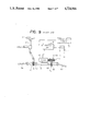
- a conventional power steering system of this type as schematically illustrated in FIG. 9, has hitherto been known in which a steering wheel 1 is operatively connected through a steering shaft 2 and a first rack and pinion gear T 1 including a first pinion 5 and a first rack tooth portion 6a with a steering rack 6 which is connected at its opposite ends with a pair of steerable road wheels (not shown) through a pair of tie rods 8a and 8b so that when the steering wheel 1 is turned by an operator, the steerable road wheels (not shown) are appropriately steered in accordance with the steering motion of the steering wheel 1 exerted by the operator.
- the steering rack 6 is operatively connected with a motor 13 through a second rack and pinion gear including a second rack tooth portion 6b and a second pinion 18, a speed-reduction gear R, and a switching clutch 17 so that the driving force of the motor 13 is transmitted through the speed-reduction gear R, the switching clutch 17 and the second rack and pinion gear T 2 to the rack 6 so as to assist the steering operation of the steering wheel 1 exerted by the operator.
- the motor 13 is electrically connected with a battery 11 through a control unit 9 and a key or ignition switch 12 so that it is energized by the battery 11 under the control of the control unit 9.
- the control unit 9 is input with control signals from a steering-torque sensor 3 and a vehicle-speed sensor 10 so as to appropriately control the operation of the motor 13 and the switching clutch 17 on the basis of the steering torque and the vehicle speed measured.
- the power steering system as constructed above has the following problems. Specifically, when the travelling speed of the vehicle increases above or decreases below a prescribed level, the control unit 9 operates to deenergize or energize the switching clutch 17 to interrupt and establish the transmission of the assisting force from the motor 13 to the rack 6, so as to switch the power steering system into a manual steering mode without any power assist or into a power steering mode with power assist. Accordingly, whenever the vehicle speed changes across a prescribed speed level, the operating mode of the steering system abruptly changes from power steering into manual steering or vice versa, thus causing the operator to feel a certain unsmoothness, unsureness, or instability in the steering.
- the present invention has the objective of eliminating the above-described problem of the prior art, and has for its main object the provision of a novel and improved motor-driven power steering system for a vehicle which can be switched or transferred from power steering into manual steering or vice versa in an extremely smooth manner without causing any unsure feelings.
- a motor-driven power steering system for a vehicle having a steering wheel operatively connected with steerable road wheels in response to a force exerted thereon by an operator, the motor-driven power steering system comprising:
- a torque sensor connected to detect operator-induced steering torque resulting from steering force exerted on the steering wheel by the operator to generate an output signal representative thereof
- a vehicle-speed sensor for detecting vehicle speed to generate an output signal representative of the detected vehicle speed
- a motor operatively connected to the steerable road wheels and energized by a battery to transmit a force to the steerable road wheels for power assisting the steering motion caused by the operator through the steering wheel;
- a first electromagnetic sliding clutch for controlling the power-assisting force transmitted from the motor to the steerable road wheels
- a second electromagnetic switching clutch connected to be switched off for interrupting the transmission of the power-assisting force from the motor toward the steerable road wheels when the vehicle speed increases above a prescribed level, and switched on for transmission of the power-steering force therebetween when the vehicle speed decreases below the prescribed level;
- control unit connected to receive output signals from the torque sensor and the vehicle-speed sensor for controlling respective running and switching operations of the motor and the first clutch in such a manner that the power-assisting force transmitted from the motor to the steerable road wheels through the first sliding clutch is gradually decreased before the second clutch is switched off, and gradually increased after the second clutch is switched on.
- a motor-driven power steering system for a vehicle comprising:
- a steering shaft fixedly connected with the steering wheel for integral rotation therewith;
- a vehicle-speed sensor for detecting travelling speed of the vehicle to generate an output signal representative of the detected vehicle speed
- a torque sensor mounted on the steering shaft for detecting operator-induced steering torque resulting from steering force exerted on the steering wheel by an operator to generate an output signal representative of the detected steering torque
- a first pinion operatively connected with the steering shaft and connected to be driven by the steering wheel through the intermediary of the steering shaft;
- a rack operatively connected through tie rods with a pair of steerable road wheels and having a first rack tooth portion and a second rack tooth portion formed thereon, the first rack tooth portion being in meshing engagement with the first pinion;
- a motor adapted to be energized by a battery and operatively connected through a speed-reduction gear with the second pinion for power assisting steering motion of the rack induced by the operator through the intermediary of the steering wheel, the steering shaft, the first pinion and the first rack tooth portion;
- a first electromagnetic sliding clutch interposed between the motor and the second pinion for transmitting power therebetween substantially in proportion to the current supplied thereto;
- a second electromagnetic switching clutch interposed between the motor and the second pinion for selectively disconnecting the operative connection between the motor and the second pinion when the vehicle speed increases above as prescribed level and establishing the operative connection therebetween when the vehicle speed decreases below the prescribed level;
- control unit connected to receive output signals from the torque sensor and the vehicle-speed sensor for controlling respective running and switching operations of the motor and the first clutch in such a manner that the power-assisting force transmitted from the motor toward the rack through the first clutch is gradually decreased before the second clutch is switched off, and gradually increased after the second clutch is switched on.
- the power-assisting torque transmitted from the motor toward the rack through the first clutch is gradually decreased or increased in inverse proportion to the measured vehicle speed.
- a power-assisting torque may be gradually decreased or increased in a stepwise fashion.
- control unit comprises:
- a steering-torque measuring means connected to receive the output signal of the torque sensor for measuring the operator-induced steering torque
- a vehicle-speed measuring means connected to receive the output signal of the vehicle-speed sensor for measuring the vehicle speed
- a memory means for storing predetermined current values corresponding to varying vehicle speeds and steering torques
- a clutch-current determining means connected to read out from the memory means an appropriate current value corresponding to the measured steering torque and the measured vehicle speed for determining current to be supplied to the first clutch;
- a clutch-current controlling means for controlling the switching operation of the first clutch in accordance with the current determined by the clutch-current determining means.
- the memory means comprise:
- a reduction-ratio storage means for storing second predetermined reduction ratios of the steering torque corresponding to varying vehicle speeds
- control-torque calculating means connected to read out from the reduction-ratio storage means an appropriate reduction ratio corresponding to the measured vehicle speed and for calculating an appropriate control torque by multiplying the measured steering torque by the corresponding reduction ratio so as to determine the current to be supplied to the first sliding clutch on the basis of the calculated control torque.
- control unit comprises:
- a steering-torque measuring means connected to receive the output signal of the torque sensor for measuring the operator-induced steering torque
- a vehicle-speed measuring means connected to receive the output signal of the vehicle-speed sensor for measuring the vehicle speed
- a memory means for storing predetermined voltage values corresponding to varying vehicle speeds and steering torques
- a motor-voltage determining means connected to read out from the memory means an appropriate voltage value corresponding to the measured steering torque and the measured vehicle-speed for determining the voltage to be imposed on the motor;
- a motor-voltage controlling means for controlling the running operation of the motor in accordance with the voltage determined by the motor-voltage determining means.
- the memory means comprise;
- a reduction-ratio storage means for storing predetermined reduction ratios of the steering torque corresponding to varying vehicle speeds
- control-torque calculating means connected to read out from the reduction-ratio storage means an appropriate reduction ratio corresponding to the measured vehicle speed and for calculating an appropriate control torque by multiplying the measured steering torque by the corresponding reduction ratio so as to determine the voltage to be imposed on the motor on the basis of the calculated control torque.
- control unit comprises:
- a steering-torque measuring means connected to receive the output signal of the torque sensor for measuring the operator-induced steering torque
- a vehicle-speed measuring means connected to receive the output signal of the vehicle-speed sensor for measuring the vehicle speed
- a first memory means for storing predetermined voltage values corresponding to varying vehicle speeds and steering torques
- a motor-voltage determining means connected to read out from the first memory means an appropriate voltage value corresponding to the measured steering torque and the measured vehicle-speed for determining the voltage to be imposed on the motor;
- a motor-voltage controlling means for controlling the running operation of the motor in accordance with the voltage determined by the motor-voltage determining means
- a second memory means for storing predetermined current values corresponding to varying vehicle speeds and steering torques
- a clutch-current determining means connected to read out from the second memory means an appropriate current value corresponding to the measured steering torque and the measured vehicle-speed for determining the current to be supplied to the first clutch;
- a clutch-current controlling means for controlling the switching operation of the first clutch in accordance with the current determined by the clutch-current determining means.
- the first memory means comprises:
- a first reduction-ratio storage means for storing first predetermined reduction ratios of the steering torque corresponding to varying vehicle speeds
- a first control-torque calculating means connected to read out from the first reduction ratio storage means a first appropriate reduction ratio corresponding to the measured vehicle speed and for calculating a first appropriate control torque by multiplying the measured steering torque by the corresponding first reduction ratio so as to determine the voltage to be imposed on the motor on the basis of the first calculated control torque;
- a second reduction-ratio storage means for storing second predetermined reduction ratios of the steering torque corresponding to varying vehicle speeds
- a second control-torque calculating means connected to read out from the second reduction ratio storage means a second appropriate reduction ratio corresponding to the measured vehicle speed and for calculating a second appropriate control torque by multiplying the measured steering torque by the corresponding second reduction ratio current to be supplied to the first sliding clutch on the basis of the second calculated control torque.
- FIGS. 1 through 8 relate to a motor-driven power steering system in accordance with one embodiment of the present invention, in which
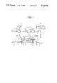
- FIG. 1 is a schematic view illustrating a general arrangement of the same
- FIG. 2 is a block diagram showing a control unit and its related parts
- FIG. 3 is a block diagram showing a motor-voltage storage means and a clutch-current storage means of the control unit;
- FIG. 4 is a graphic representation showing current/torque characteristics of a first electromagnetic clutch
- FIG. 5 is a characteristic view showing a steering-torque/motor-voltage relationship and a steering-torque/first-clutch-current relationship when the vehicle is standing still;
- FIG. 6 is a characteristic view showing a steering torque/first-clutch-current relationship when the vehicle speed changes
- FIG. 7 is a characteristic view showing a vehicle speed/first-clutch current relationship and a vehicle speed/second-clutch current relationship when the steering torque is constant;
- FIG. 8 is a flow chart showing the control processes of the power steering system of FIG. 1 as controlled by the control unit illustrated in FIG. 2.
- FIG. 9 is a schematic view illustrating a general arrangement of a conventional motor-driven power steering system for a vehicle.
- FIG. 1 there is shown a general arrangement of a motor-driven power steering system for a vehicle constructed in accordance with the present invention.
- the motor-driven power steering system illustrated includes a steering wheel 1; a steering shaft 2 fixedly connected at its upper end with the steering wheel for integral rotation therewith and including an upper section 2a and a lower section 2b joined with each other through a first universal joint 4a; a torque sensor 3 mounted on the steering shaft 2 for detecting operator-induced steering torque resulting from steering force exerted on the steering wheel 1 by an operator and generating an electrical signal representative of the detected steering torque; a first pinion 5 operatively connected at its upper end with the the lower end of the steering shaft 2 through a second universal joint 4b; a rack 6 operatively connected at its opposite ends through ball joints 7a, 7b with tie rods 8a, 8b which are in turn connected with a pair of steerable road wheels (not shown), the rack 6 having a first tooth portion 6a in mesh with the first pinion 5 and a second tooth
- the speed-reduction gear R comprises a worm 15 operatively connected with an output shaft of the first sliding clutch 14, and a worm wheel 16 in mesh with the worm 15.
- the second electromagnetic switching clutch 17 serves to mechanically couple or disconnect the worm wheel 16 with the second pinion 18.
- the control unit 109 comprises: a steering-torque measuring means 109a connected to receive the output signal of the torque sensor 3 for measuring the operator-induced steering torque; a vehicle-speed measuring means 109b connected to receive the output signal of the the vehicle-speed sensor 10 for measuring the vehicle speed; a first memory means 109c for storing predetermined voltage values corresponding to varying vehicle speeds and steering torques; a motor-voltage determining means 109d connected to read out from the first memory means 109c an appropriate voltage value corresponding to the measured steering torque and the measured vehicle-speed for determining the voltage to be imposed on the motor 13; a second memory means 109e for storing predetermined current values corresponding to varying vehicle speeds and steering torques; a clutch-current determining means 109f connected to read out from the second memory means 109e an appropriate current value corresponding to the measured steering torque and the measured vehicle-speed for determining the current to be supplied to the first electromagnetic sliding clutch 14; a motor-voltage controlling means 109g for
- the first memory means 109c comprises: a first reduction-ratio storage means 209a for storing first predetermined reduction ratios of the steering torque corresponding to varying vehicle speeds; and a first control-torque calculating means 209b connected to read out from the reduction-ratio storage means an appropriate reduction ratio corresponding to the measured vehicle speed and for calculating a first appropriate control torque by multiplying the measured steering torque by the corresponding first reduction ratio so as to determine voltage to be imposed on the motor on the basis of the first calculated control torque.
- the second memory means 109e comprises: a second reduction-ratio storage means 209c for storing second predetermined reduction ratios of the steering torque corresponding to varying vehicle speeds; and a second control-torque calculating means 209d connected to read out from the second reduction ratio storage means a second appropriate reduction ratio corresponding to the measured vehicle speed and for calculating a second appropriate control torque by multiplying the measured steering torque by the corresponding second reduction ratio so as to determine the current to be supplied to the second switching clutch on the basis of the second calculated control torque.
- FIGS. 1 through 8 the case in which a vehicle is stationary or standing still will be considered.
- the electromagnetic clutch 17 is automatically actuated to place the second pinion 18 into mechanical coupling with the worm wheel 16.
- the control unit 109 acts to control the operations of the motor 13 and the sliding clutch 14 in the manner as illustrated in FIG. 5 which shows a relationship between steering torque, motor voltage and clutch current. More specifically, when steering torque increases in the righthand direction to point a in FIG. 5, the motor 13 is turned on and then imposed with 100% voltage at point b.
- the characteristic of the sliding clutch 14 is used in a range in which transmitting torque or sliding torque increases substantially in direct proportion to clutch current. Accordingly, as is clear from FIG. 5, the motor 13 is imposed with 100% voltage and energized to start rotating when steering torque increases to point a. As the steering torque further increases, current flowing through the sliding clutch 14 begins to gradually increase at point c so that the output torque transmitted from the sliding clutch 14 to the worm 15 increases gradually. As a result, auxiliary torque having an intensity corresponding to the turning force exerted on the steering wheel by an operator is transmitted from the motor 13 to the second tooth portion 6b on the rack 6 via the sliding clutch 14, the worm wheel 16, the electromagnetic clutch 17 and the second pinion 18, thereby lightening the steering operation for the operator.
- the clutch current supplied to the first sliding clutch 14 is controlled to decrease in a stepwise fashion in inverse proportion to an increase in the vehicle speed.
- the clutch current is controlled by the control torque determined by the product of the steering torque and a reduction ratio which corresponds to the vehicle speed so that it gradually decreases in a stepwise manner as illustrated in FIG. 7.
- the clutch current is made zero at point f even when steering torque is exerted on the steering wheel 1.
- the second electromagnetic switching clutch 17 is switched off or deenergized to release the engagement or mechanical coupling between the worm wheel 16 and the second pinion 18, thereby switching the steering system into a manual steering mode without any power assist.
- the torque transmitted from the motor 13 to the rack 6 is gradually decreased in accordance with an increase in the vehicle speed under the action of the first sliding clutch 14 so that it is made zero before switching off or deenergization of the second switching clutch 17.
- the transmission torque or sliding torque of the first sliding clutch 14 begins to increase after the second switching clutch 17 is energized to mechanically couple the worm wheel 16 with the second pinion 18.
- the steering system can change over from the power steering mode into the manual steering mode or vice versa in an extremely smooth manner without giving rise to any feelings of unsureness or instability which would otherwise be caused by abrupt connection or disconnection of the second switching clutch 17.
- the voltage imposed on the motor 13 is likewise controlled in the same manner as the current supplied to the first sliding clutch 14. Though not illustrated, it is possible to control either the motor voltage or the clutch current supplied to the first sliding clutch 14 alone.
- the above control of the power steering system can be installed simply by replacing the conventional control program of a control unit with that of the present invention without changing the general arrangement of a conventional power steering system. Accordingly, it is possible to manufacture the motor-driven power steering system of the present invention at low cost.
Landscapes
- Engineering & Computer Science (AREA)
- Chemical & Material Sciences (AREA)
- Combustion & Propulsion (AREA)
- Transportation (AREA)
- Mechanical Engineering (AREA)
- Steering Control In Accordance With Driving Conditions (AREA)
- Power Steering Mechanism (AREA)
Applications Claiming Priority (4)
| Application Number | Priority Date | Filing Date | Title |
|---|---|---|---|
| JP61-63490 | 1986-03-19 | ||
| JP61063489A JPS62218276A (ja) | 1986-03-19 | 1986-03-19 | モ−タ駆動式パワ−ステアリング制御方法 |
| JP61-63489 | 1986-03-19 | ||
| JP61063490A JPS62218277A (ja) | 1986-03-19 | 1986-03-19 | モ−タ駆動式パワ−ステアリング制御方法 |
Publications (1)
| Publication Number | Publication Date |
|---|---|
| US4724916A true US4724916A (en) | 1988-02-16 |
Family
ID=26404619
Family Applications (1)
| Application Number | Title | Priority Date | Filing Date |
|---|---|---|---|
| US07/026,466 Expired - Fee Related US4724916A (en) | 1986-03-19 | 1987-03-16 | Motor-driven power steering system for a vehicle |
Country Status (4)
| Country | Link |
|---|---|
| US (1) | US4724916A (de) |
| EP (1) | EP0238347B1 (de) |
| KR (1) | KR900001849B1 (de) |
| DE (1) | DE3768107D1 (de) |
Cited By (6)
| Publication number | Priority date | Publication date | Assignee | Title |
|---|---|---|---|---|
| US5007494A (en) * | 1988-05-30 | 1991-04-16 | Mazda Motor Corporation | Rear wheel turning system |
| US5067577A (en) * | 1989-05-24 | 1991-11-26 | Mitsubishi Denki Kabushiki Kaisha | Motor-driven type front and rear wheel steering apparatus |
| EP0792786A3 (de) * | 1996-03-01 | 1998-05-20 | Lucas Industries Public Limited Company | Steueranlage für den Kupplungsstrom und elektromotorische Servolenkeinrichtung |
| US5999870A (en) * | 1987-03-04 | 1999-12-07 | Mitsubishi Denki Kabushiki Kaisha | Motor-driven power steering system for a vehicle and a method for controlling same |
| WO2017112676A1 (en) * | 2015-12-22 | 2017-06-29 | Uber Technologies, Inc. | Integrated clutch steering system |
| CN114435466A (zh) * | 2022-01-20 | 2022-05-06 | 河北工程大学 | 一种可实现模式切换的线控转向系统及其控制方法 |
Families Citing this family (1)
| Publication number | Priority date | Publication date | Assignee | Title |
|---|---|---|---|---|
| FR2692219B1 (fr) * | 1992-06-11 | 1997-04-25 | Renault | Procede et dispositif d'assistance de direction d'un vehicule. |
Citations (7)
| Publication number | Priority date | Publication date | Assignee | Title |
|---|---|---|---|---|
| JPS5799468A (en) * | 1980-12-08 | 1982-06-21 | Tokai T R W Kk | Power steering device |
| EP0148664A1 (de) * | 1983-12-16 | 1985-07-17 | Automobiles Citroen | Durch elektrischen Motor unterstützte Kraftfahrzeuglenkung |
| US4538698A (en) * | 1983-01-17 | 1985-09-03 | Aisin Seiki Kabushiki Kaisha | Motor-driven power steering system |
| US4577715A (en) * | 1983-07-22 | 1986-03-25 | Nippon Seiko Kabushiki Kaisha | Power assist steering gear assembly |
| DE3542033A1 (de) * | 1984-11-29 | 1986-06-05 | Fuji Jukogyo K.K., Tokio/Tokyo | Elektrische kraftlenkanordnung |
| US4651840A (en) * | 1985-02-26 | 1987-03-24 | Honda Giken Kogyo Kabushiki Kaisha | Motor-driven power steering system |
| US4660669A (en) * | 1984-07-20 | 1987-04-28 | Honda Giken Kogyo Kabushiki Kaisha | Electromagnetic servo unit |
Family Cites Families (1)
| Publication number | Priority date | Publication date | Assignee | Title |
|---|---|---|---|---|
| FR2242009A5 (en) * | 1973-08-20 | 1975-03-21 | Andriussi Francois | Power assist device for steering wheel - has electromechanical shaft drive responsive to shaft rotation |
-
1987
- 1987-03-12 KR KR1019870002226A patent/KR900001849B1/ko not_active Expired
- 1987-03-16 US US07/026,466 patent/US4724916A/en not_active Expired - Fee Related
- 1987-03-19 EP EP87302393A patent/EP0238347B1/de not_active Expired - Lifetime
- 1987-03-19 DE DE8787302393T patent/DE3768107D1/de not_active Expired - Lifetime
Patent Citations (7)
| Publication number | Priority date | Publication date | Assignee | Title |
|---|---|---|---|---|
| JPS5799468A (en) * | 1980-12-08 | 1982-06-21 | Tokai T R W Kk | Power steering device |
| US4538698A (en) * | 1983-01-17 | 1985-09-03 | Aisin Seiki Kabushiki Kaisha | Motor-driven power steering system |
| US4577715A (en) * | 1983-07-22 | 1986-03-25 | Nippon Seiko Kabushiki Kaisha | Power assist steering gear assembly |
| EP0148664A1 (de) * | 1983-12-16 | 1985-07-17 | Automobiles Citroen | Durch elektrischen Motor unterstützte Kraftfahrzeuglenkung |
| US4660669A (en) * | 1984-07-20 | 1987-04-28 | Honda Giken Kogyo Kabushiki Kaisha | Electromagnetic servo unit |
| DE3542033A1 (de) * | 1984-11-29 | 1986-06-05 | Fuji Jukogyo K.K., Tokio/Tokyo | Elektrische kraftlenkanordnung |
| US4651840A (en) * | 1985-02-26 | 1987-03-24 | Honda Giken Kogyo Kabushiki Kaisha | Motor-driven power steering system |
Cited By (8)
| Publication number | Priority date | Publication date | Assignee | Title |
|---|---|---|---|---|
| US5999870A (en) * | 1987-03-04 | 1999-12-07 | Mitsubishi Denki Kabushiki Kaisha | Motor-driven power steering system for a vehicle and a method for controlling same |
| US5007494A (en) * | 1988-05-30 | 1991-04-16 | Mazda Motor Corporation | Rear wheel turning system |
| US5067577A (en) * | 1989-05-24 | 1991-11-26 | Mitsubishi Denki Kabushiki Kaisha | Motor-driven type front and rear wheel steering apparatus |
| EP0792786A3 (de) * | 1996-03-01 | 1998-05-20 | Lucas Industries Public Limited Company | Steueranlage für den Kupplungsstrom und elektromotorische Servolenkeinrichtung |
| WO2017112676A1 (en) * | 2015-12-22 | 2017-06-29 | Uber Technologies, Inc. | Integrated clutch steering system |
| EP3393887A4 (de) * | 2015-12-22 | 2018-12-26 | Uber Technologies, Inc. | Integriertes kupplungslenksystem |
| CN114435466A (zh) * | 2022-01-20 | 2022-05-06 | 河北工程大学 | 一种可实现模式切换的线控转向系统及其控制方法 |
| CN114435466B (zh) * | 2022-01-20 | 2023-09-22 | 河北工程大学 | 一种可实现模式切换的线控转向系统及其控制方法 |
Also Published As
| Publication number | Publication date |
|---|---|
| KR900001849B1 (ko) | 1990-03-24 |
| KR870008745A (ko) | 1987-10-20 |
| DE3768107D1 (de) | 1991-04-04 |
| EP0238347B1 (de) | 1991-02-27 |
| EP0238347A3 (en) | 1988-08-17 |
| EP0238347A2 (de) | 1987-09-23 |
Similar Documents
| Publication | Publication Date | Title |
|---|---|---|
| US4762194A (en) | Motor-driven power steering system for a vehicle | |
| US4837690A (en) | Motor-driven power steering system for a vehicle | |
| US4757869A (en) | Motor-driven power steering system for a vehicle | |
| EP0249506B1 (de) | Motorbetriebene Servolenkung für Fahrzeuge | |
| US4778021A (en) | Motor-driven power steering system for a vehicle | |
| US4754828A (en) | Motor-driven power steering system for a vehicle | |
| EP0304491A1 (de) | Motorbetriebene servolenkung für fahrzeuge. | |
| US4754830A (en) | Motor-driven power steering system for a vehicle | |
| US4862366A (en) | Motor-driven power steering system for a vehicle | |
| US4939436A (en) | Motor driven type power steering control device | |
| US4849889A (en) | Motor-driven power steering system for a vehicle | |
| US4724916A (en) | Motor-driven power steering system for a vehicle | |
| JPH069973B2 (ja) | モ−タ駆動式パワ−ステアリング制御装置 | |
| US4724915A (en) | Device for controlling a motor-driven power steering system for a vehicle | |
| JPH069972B2 (ja) | モ−タ駆動式パワ−ステアリング制御装置 | |
| JPS61275059A (ja) | 電動式パワ−ステアリング装置 | |
| JPH0629031B2 (ja) | モ−タ駆動式パワ−ステアリング制御装置 | |
| JPH0686219B2 (ja) | モ−タ駆動式パワ−ステアリング装置 | |
| JPH069981B2 (ja) | モ−タ駆動式パワ−ステアリング制御装置 |
Legal Events
| Date | Code | Title | Description |
|---|---|---|---|
| AS | Assignment |
Owner name: MITSUBISHI DENKI KABUSHIKI KAISHA, 2-3, MARUNOUCHI Free format text: ASSIGNMENT OF ASSIGNORS INTEREST.;ASSIGNORS:MORISHITA, MITSUHARU;KOHGE, SHINICHI;TERAUCHI, KOJI;REEL/FRAME:004708/0180 Effective date: 19870312 |
|
| FEPP | Fee payment procedure |
Free format text: PAYOR NUMBER ASSIGNED (ORIGINAL EVENT CODE: ASPN); ENTITY STATUS OF PATENT OWNER: LARGE ENTITY |
|
| FPAY | Fee payment |
Year of fee payment: 4 |
|
| FEPP | Fee payment procedure |
Free format text: PAYER NUMBER DE-ASSIGNED (ORIGINAL EVENT CODE: RMPN); ENTITY STATUS OF PATENT OWNER: LARGE ENTITY Free format text: PAYOR NUMBER ASSIGNED (ORIGINAL EVENT CODE: ASPN); ENTITY STATUS OF PATENT OWNER: LARGE ENTITY |
|
| REMI | Maintenance fee reminder mailed | ||
| LAPS | Lapse for failure to pay maintenance fees | ||
| FP | Lapsed due to failure to pay maintenance fee |
Effective date: 19960221 |
|
| STCH | Information on status: patent discontinuation |
Free format text: PATENT EXPIRED DUE TO NONPAYMENT OF MAINTENANCE FEES UNDER 37 CFR 1.362 |