US4736392A - Demodulator for digital FM signals - Google Patents
Demodulator for digital FM signals Download PDFInfo
- Publication number
- US4736392A US4736392A US06/857,859 US85785986A US4736392A US 4736392 A US4736392 A US 4736392A US 85785986 A US85785986 A US 85785986A US 4736392 A US4736392 A US 4736392A
- Authority
- US
- United States
- Prior art keywords
- corrector
- cascade
- distortion
- sup
- signals
- Prior art date
- Legal status (The legal status is an assumption and is not a legal conclusion. Google has not performed a legal analysis and makes no representation as to the accuracy of the status listed.)
- Expired - Lifetime
Links
- 230000009467 reduction Effects 0.000 claims abstract description 8
- 238000001914 filtration Methods 0.000 claims abstract description 5
- 230000000694 effects Effects 0.000 claims abstract 3
- 238000012937 correction Methods 0.000 claims description 13
- 238000005070 sampling Methods 0.000 claims description 13
- 230000003111 delayed effect Effects 0.000 claims 3
- 230000010485 coping Effects 0.000 claims 1
- 230000001629 suppression Effects 0.000 claims 1
- 238000010586 diagram Methods 0.000 description 7
- 230000008901 benefit Effects 0.000 description 3
- 230000005540 biological transmission Effects 0.000 description 3
- 238000011045 prefiltration Methods 0.000 description 3
- 238000012545 processing Methods 0.000 description 2
- 230000004044 response Effects 0.000 description 2
- 238000007792 addition Methods 0.000 description 1
- 238000006243 chemical reaction Methods 0.000 description 1
- 238000005352 clarification Methods 0.000 description 1
- 238000013016 damping Methods 0.000 description 1
- 238000011161 development Methods 0.000 description 1
- 230000018109 developmental process Effects 0.000 description 1
- 238000003780 insertion Methods 0.000 description 1
- 230000037431 insertion Effects 0.000 description 1
- 238000004519 manufacturing process Methods 0.000 description 1
- 238000000034 method Methods 0.000 description 1
- 238000012986 modification Methods 0.000 description 1
- 230000004048 modification Effects 0.000 description 1
- 230000008569 process Effects 0.000 description 1
- 230000005855 radiation Effects 0.000 description 1
Images



Classifications
-
- H—ELECTRICITY
- H04—ELECTRIC COMMUNICATION TECHNIQUE
- H04B—TRANSMISSION
- H04B7/00—Radio transmission systems, i.e. using radiation field
- H04B7/005—Control of transmission; Equalising
-
- H—ELECTRICITY
- H03—ELECTRONIC CIRCUITRY
- H03D—DEMODULATION OR TRANSFERENCE OF MODULATION FROM ONE CARRIER TO ANOTHER
- H03D3/00—Demodulation of angle-, frequency- or phase- modulated oscillations
- H03D3/007—Demodulation of angle-, frequency- or phase- modulated oscillations by converting the oscillations into two quadrature related signals
-
- H—ELECTRICITY
- H03—ELECTRONIC CIRCUITRY
- H03H—IMPEDANCE NETWORKS, e.g. RESONANT CIRCUITS; RESONATORS
- H03H17/00—Networks using digital techniques
- H03H17/02—Frequency selective networks
- H03H17/04—Recursive filters
-
- H—ELECTRICITY
- H03—ELECTRONIC CIRCUITRY
- H03D—DEMODULATION OR TRANSFERENCE OF MODULATION FROM ONE CARRIER TO ANOTHER
- H03D2200/00—Indexing scheme relating to details of demodulation or transference of modulation from one carrier to another covered by H03D
- H03D2200/0041—Functional aspects of demodulators
- H03D2200/005—Analog to digital conversion
-
- H—ELECTRICITY
- H03—ELECTRONIC CIRCUITRY
- H03D—DEMODULATION OR TRANSFERENCE OF MODULATION FROM ONE CARRIER TO ANOTHER
- H03D2200/00—Indexing scheme relating to details of demodulation or transference of modulation from one carrier to another covered by H03D
- H03D2200/0041—Functional aspects of demodulators
- H03D2200/0054—Digital filters
-
- H—ELECTRICITY
- H03—ELECTRONIC CIRCUITRY
- H03D—DEMODULATION OR TRANSFERENCE OF MODULATION FROM ONE CARRIER TO ANOTHER
- H03D2200/00—Indexing scheme relating to details of demodulation or transference of modulation from one carrier to another covered by H03D
- H03D2200/0041—Functional aspects of demodulators
- H03D2200/0092—Detection or reduction of fading in multipath transmission arrangements
-
- H—ELECTRICITY
- H03—ELECTRONIC CIRCUITRY
- H03D—DEMODULATION OR TRANSFERENCE OF MODULATION FROM ONE CARRIER TO ANOTHER
- H03D3/00—Demodulation of angle-, frequency- or phase- modulated oscillations
- H03D3/006—Demodulation of angle-, frequency- or phase- modulated oscillations by sampling the oscillations and further processing the samples, e.g. by computing techniques
Definitions
- This invention concerns a demodulator for frequency modulated (FM) signals in digital form equipped with non-recursive filters constituted as a distortion-correcting network for filtering the signals and with an analog-to-digital converter for digitizing the frequency modulated signals, as well as an analog band-pass filter ahead of the input of the analog-to-digital converter and having a relatively narrow pass-band.
- FM frequency modulated
- narrow-band prefiltering is proposed in order to prevent adjacent channel transmitters from falling alongside to the signal being received in the pass-band of the analog prefilter.
- the narrow-band IF filtering that is now conditional upon the analog prefiltering, however, brings along with it great phase and damping distortions.
- a distortion correcting network instead of the low-pass filter of the above-described known demodulator, a distortion correcting network should be used which removes or compensates for the phase and attenuation distortions of the narrow-band prefilter.
- the digital distortion corrector in the form of a distortion correcting network no longer has the function of providing selective tuning, but serves rather for compensation of the far-from-ideal properties of the analog prefilter.
- the distortion corrector for compensation of multi-path reception is provided by a cascade non-recursive filter constituted by a number of distortion corrector blocks connected in series, each of which provides a raising of the phase rotation and of the propagation time as well as a reduction of the reflection factor of the reflected component contained in the input signal.
- each partial distortion corrector can be constituted with the least possible hardware expense and thereby the total expense of a unit constituted as a cascade of several distortion correctors can be found substantially less than the expense in the case of the transversal network arrangement described in the above-identified prior German patent application.
- FIG. 1 is a block circuit diagram of the filter structure in the case of the demodulator proposed by the above-mentioned earlier German patent application;
- FIG. 2 is a circuit block diagram of a distortion correcting branch of the demodulator of FIG. 1;
- FIG. 3 is a diagram of a modified distortion correction branch for compensation of a simple reflection in the case of the demodulator of FIG. 1;
- FIG. 4 is a basic schematic representation of a cascade distortion corrector consisting of several distortion correction blocks
- FIG. 5 is a basic diagram of a non-recursive distortion corrector corresponding to the first distortion corrector block of FIG. 4;
- FIG. 6 is a representation similar to FIG. 5 for the second distortion correction block of FIG. 4;
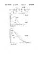
- FIGS. 7 and 8 are both diagrams for the coefficient of harmonic distortion as a function of the number of distortion correction blocks used
- FIG. 9 is a schematic circuit block diagram for making clear the hardware requirements of a distortion correction.
- FIG. 10 is a basic diagram of a distortion corrector block for the case of a relative amplitude of the reflection component which is greater than "1".
- FIGS. 1-3 of the drawings show a digital demodulator which is described in the above-mentioned earlier German patent application, which may be regarded as the starting point from which the invention was developed.
- FIG. 1 shows the portion of a digital receiver 10 which concerns the present invention.
- a band-pass filter 14 is connected to follow an IF mixer 12 and supplies its output to an analog-to-digital converter 16.
- FIG. 1 shows two non-recursive filters connected respectively to the adding units 30 and 32 and also respectively connected to the multipliers 18 and 20.
- the outputs of the digital adding units 30 and 32 are supplied to a demodulator 34 in order to produce low-frequency signals.
- the calculation of the distortion correction coefficients is carried out in the case of the demodulator proposed in the earlier patent application by minimizing the error of the resulting pulse response (least error squares). This is all explained more fully in the prior patent application so that it is not necessary at this place to go into the matter further.
- the invention now provides a non-recursive cascade type of filter with, in the illustrated case, five distortion correction blocks 44, 46, 48, 50 and 52 connected one after the other for the compensation of multi-path reception.
- a received FM signal z(k) disturbed by a reflection produces the output signal y 5 (k), the form of which will be further explained below.
- This signal is supplied to a system of the kind shown in FIG. 5, which shows the first distortion corrector block 44 and delay circuits 54, a multiplier 56 containing an adding unit 58.
- the output signal y 1 (k) then has the form: ##EQU2##
- the processing above described is repeated in a correspondingly modified network--here in the second distortion corrector block 46 shown in FIG. 6.
- the output signal y 2 (k) of the second distortion corrector block 46 is described, on the basis of the above consideration, as follows:
- the reflection factor is now reduced to ⁇ 4 .
- this process is repeated often enough for the reflection factor to become sufficiently small.
- the following reflection parameter is obtained:
- the harmonic distortion coefficient (non-linear distortion coefficient) of the demodulated signal is graphed in FIGS. 7 and 8 as the function of the number n of the distortion corrector blocks 44-52.
- the various curves in FIG. 7 in each case relate to different reflection factors ⁇ .
- the harmonic distortion coefficient K reaches a vanishingly small value with five distortion corrector blocks.
- a significant advantage of the invention consists in that the modified structure for the distortion corrector leads to the remarkable reduction of the hardware expense.
- FIG. 9 shows in general form the constitution of an nth distortion corrector block.
- the two inputs of the distortion corrector block are resectively connected to a first and a second signal path which respectively contain shift registers 64 and 66.
- the input of the shift register 64 is connected to a first adding unit 78, while the input of the other shift register 66 is connected to another adding unit 82.
- Two multipliers 68 and 70 are connected to the shift register 64.
- the first multiplier 68 is connected with the first adding unit 76, while the second multiplier 70 is connected with a third adding unit 80 in the second signal path.
- a third multiplier 72 which is connected to a third adding unit 80 and, furthermore, the output of the shift register 66 is also connected to a fourth multiplier 74 which is connected with the first adding unit 76.
- the two multipliers 68 and 72 are also provided with the same multiplying factor a n , which may be a signal source providing a constant voltage of a magnitude representative of the multiplying factor in question, as symbolically shown in FIG. 9
- the input signal y n-1 (k) is supplied to a multiplier 84 and also to a delay circuit 88.
- An adding unit 86 is connected to the multiplier 84 which is also connected with the output of the delay circuit 88.
Landscapes
- Engineering & Computer Science (AREA)
- Power Engineering (AREA)
- Computer Networks & Wireless Communication (AREA)
- Signal Processing (AREA)
- Physics & Mathematics (AREA)
- Computer Hardware Design (AREA)
- Mathematical Physics (AREA)
- Cable Transmission Systems, Equalization Of Radio And Reduction Of Echo (AREA)
- Digital Transmission Methods That Use Modulated Carrier Waves (AREA)
Applications Claiming Priority (2)
| Application Number | Priority Date | Filing Date | Title |
|---|---|---|---|
| DE19853517485 DE3517485A1 (de) | 1985-05-15 | 1985-05-15 | Demodulator fuer frequenzmodulierte signale in digitaler form |
| DE3517485 | 1985-05-15 |
Publications (1)
| Publication Number | Publication Date |
|---|---|
| US4736392A true US4736392A (en) | 1988-04-05 |
Family
ID=6270777
Family Applications (1)
| Application Number | Title | Priority Date | Filing Date |
|---|---|---|---|
| US06/857,859 Expired - Lifetime US4736392A (en) | 1985-05-15 | 1986-04-30 | Demodulator for digital FM signals |
Country Status (4)
| Country | Link |
|---|---|
| US (1) | US4736392A (fr) |
| EP (1) | EP0201758B1 (fr) |
| JP (1) | JP2510992B2 (fr) |
| DE (2) | DE3517485A1 (fr) |
Cited By (15)
| Publication number | Priority date | Publication date | Assignee | Title |
|---|---|---|---|---|
| US4866649A (en) * | 1986-11-12 | 1989-09-12 | Siemens Aktiengesellschaft | Multi-dimensional digital filter having adders, multipliers and shift elements |
| US4947408A (en) * | 1989-05-12 | 1990-08-07 | The United States Of America As Represented By The Administrator Of The National Aeronautics And Space Administration | Digital carrier demodulator employing components working beyond normal limits |
| US4955078A (en) * | 1987-10-05 | 1990-09-04 | U.S. Philips Corporation | Frequency difference detector (FDD) having automatic gain control and a carrier modulated receiver including the FDD |
| US5014352A (en) * | 1987-10-05 | 1991-05-07 | U.S. Philips Corporation | Frequency difference detector (FDD) and a carrier modulated receiver including such a FDD |
| US5068817A (en) * | 1987-02-19 | 1991-11-26 | Ant Nachrichtentechnik Gmbh | Non-recursive half-band filter with complex valued coefficients for complex input and output signals |
| US5128966A (en) * | 1989-02-15 | 1992-07-07 | Samsung Electronics Co., Ltd. | System for demodulating frequency- or phase-modulated signals by quadrature-phase |
| US5381446A (en) * | 1993-06-25 | 1995-01-10 | Digital Wireless Corp. | Digital implementation of spread spectrum communications system |
| US5398002A (en) * | 1989-02-15 | 1995-03-14 | Samsung Electronics Co., Ltd. | Automatic frequency control system by quadrature-phase in frequency or phase demodulating system |
| US5430770A (en) * | 1994-04-22 | 1995-07-04 | Rockwell International Corp. | Method and apparatus for composite signal separation and PSK/AM/FM demodulation |
| US5493721A (en) * | 1992-11-07 | 1996-02-20 | Grundig E.M.V. | Receiver for a digital radio signal |
| US5615411A (en) * | 1994-04-22 | 1997-03-25 | Rockwell International | Method and apparatus for composite signal separation and FM demodulation |
| US5694079A (en) * | 1996-04-04 | 1997-12-02 | Lucent Technologies Inc. | Digital FM demodulator using a lagrangian interpolation function |
| US6006070A (en) * | 1995-04-07 | 1999-12-21 | Telecommunications Equipment Corporation | Multi-function interactive communications system with circularly/elliptically polarized signal transmission and reception |
| US6233435B1 (en) | 1997-10-14 | 2001-05-15 | Telecommunications Equipment Corporation | Multi-function interactive communications system with circularly/elliptically polarized signal transmission and reception |
| US20070018867A1 (en) * | 2005-07-22 | 2007-01-25 | Semiconductor Technology Academic Research Center | Band-pass delta-sigma ad modulator for ad-converting high frequency narrow signal with higher precision and lower consumption power |
Families Citing this family (6)
| Publication number | Priority date | Publication date | Assignee | Title |
|---|---|---|---|---|
| DE3444449A1 (de) * | 1984-12-06 | 1986-06-12 | Robert Bosch Gmbh, 7000 Stuttgart | Demodulator fuer digitale empfaenger |
| DE3532857A1 (de) * | 1985-09-14 | 1987-03-26 | Bosch Gmbh Robert | Digitales nichtrekursives filter |
| DE3543898A1 (de) * | 1985-12-12 | 1987-06-19 | Blaupunkt Werke Gmbh | Entzerrer in form eines digitalen nichtrekursiven filters |
| DE3916426A1 (de) * | 1989-05-19 | 1990-11-22 | Blaupunkt Werke Gmbh | Autoradio mit einem digitalen entzerrernetzwerk |
| DE4104882A1 (de) * | 1991-02-18 | 1992-08-20 | Blaupunkt Werke Gmbh | Autoradio mit einer schaltungsanordnung zur analog/digital-wandlung eines zwischenfrequenzsignals |
| DE4309684C2 (de) * | 1992-12-12 | 1995-11-23 | Ant Nachrichtentech | Verfahren zur Demodulation von frequenzmodulierten Signalen |
Citations (6)
| Publication number | Priority date | Publication date | Assignee | Title |
|---|---|---|---|---|
| US3803501A (en) * | 1972-11-17 | 1974-04-09 | Ibm | Frequency discriminator using digital non-recursive filters |
| US3979701A (en) * | 1975-06-17 | 1976-09-07 | Communications Satellite Corporation (Comsat) | Non-recursive digital filter employing simple coefficients |
| US4184129A (en) * | 1976-06-04 | 1980-01-15 | Agence Nationale De Valorisation De La Recherche (Anvar) | Systems for transmitting data between distant locations |
| US4506228A (en) * | 1981-09-26 | 1985-03-19 | Robert Bosch Gmbh | Digital FM detector |
| US4584600A (en) * | 1982-10-06 | 1986-04-22 | Itt Industries, Inc. | Digital filter for the chrominance channel of a color-television set |
| DE3444449A1 (de) * | 1984-12-06 | 1986-06-12 | Robert Bosch Gmbh, 7000 Stuttgart | Demodulator fuer digitale empfaenger |
Family Cites Families (4)
| Publication number | Priority date | Publication date | Assignee | Title |
|---|---|---|---|---|
| DE2262652C2 (de) * | 1972-12-21 | 1983-06-30 | Licentia Patent-Verwaltungs-Gmbh, 6000 Frankfurt | Digitale Filterbank |
| JPS5910094B2 (ja) * | 1978-04-12 | 1984-03-07 | 日本電気株式会社 | 振幅等化装置 |
| DE3138464A1 (de) * | 1981-09-26 | 1983-04-14 | Robert Bosch Gmbh, 7000 Stuttgart | Verfahren zur digitalen demodulation frequenzmodulierter signale |
| DE3302550A1 (de) * | 1983-01-26 | 1984-07-26 | Siemens AG, 1000 Berlin und 8000 München | Digitale phasenlineare tiefpass-filterschaltung |
-
1985
- 1985-05-15 DE DE19853517485 patent/DE3517485A1/de not_active Withdrawn
-
1986
- 1986-04-18 EP EP86105415A patent/EP0201758B1/fr not_active Expired - Lifetime
- 1986-04-18 DE DE8686105415T patent/DE3683682D1/de not_active Expired - Lifetime
- 1986-04-30 US US06/857,859 patent/US4736392A/en not_active Expired - Lifetime
- 1986-05-15 JP JP61109741A patent/JP2510992B2/ja not_active Expired - Lifetime
Patent Citations (6)
| Publication number | Priority date | Publication date | Assignee | Title |
|---|---|---|---|---|
| US3803501A (en) * | 1972-11-17 | 1974-04-09 | Ibm | Frequency discriminator using digital non-recursive filters |
| US3979701A (en) * | 1975-06-17 | 1976-09-07 | Communications Satellite Corporation (Comsat) | Non-recursive digital filter employing simple coefficients |
| US4184129A (en) * | 1976-06-04 | 1980-01-15 | Agence Nationale De Valorisation De La Recherche (Anvar) | Systems for transmitting data between distant locations |
| US4506228A (en) * | 1981-09-26 | 1985-03-19 | Robert Bosch Gmbh | Digital FM detector |
| US4584600A (en) * | 1982-10-06 | 1986-04-22 | Itt Industries, Inc. | Digital filter for the chrominance channel of a color-television set |
| DE3444449A1 (de) * | 1984-12-06 | 1986-06-12 | Robert Bosch Gmbh, 7000 Stuttgart | Demodulator fuer digitale empfaenger |
Cited By (16)
| Publication number | Priority date | Publication date | Assignee | Title |
|---|---|---|---|---|
| US4866649A (en) * | 1986-11-12 | 1989-09-12 | Siemens Aktiengesellschaft | Multi-dimensional digital filter having adders, multipliers and shift elements |
| US5068817A (en) * | 1987-02-19 | 1991-11-26 | Ant Nachrichtentechnik Gmbh | Non-recursive half-band filter with complex valued coefficients for complex input and output signals |
| US4955078A (en) * | 1987-10-05 | 1990-09-04 | U.S. Philips Corporation | Frequency difference detector (FDD) having automatic gain control and a carrier modulated receiver including the FDD |
| US5014352A (en) * | 1987-10-05 | 1991-05-07 | U.S. Philips Corporation | Frequency difference detector (FDD) and a carrier modulated receiver including such a FDD |
| US5128966A (en) * | 1989-02-15 | 1992-07-07 | Samsung Electronics Co., Ltd. | System for demodulating frequency- or phase-modulated signals by quadrature-phase |
| US5398002A (en) * | 1989-02-15 | 1995-03-14 | Samsung Electronics Co., Ltd. | Automatic frequency control system by quadrature-phase in frequency or phase demodulating system |
| US4947408A (en) * | 1989-05-12 | 1990-08-07 | The United States Of America As Represented By The Administrator Of The National Aeronautics And Space Administration | Digital carrier demodulator employing components working beyond normal limits |
| US5493721A (en) * | 1992-11-07 | 1996-02-20 | Grundig E.M.V. | Receiver for a digital radio signal |
| US5381446A (en) * | 1993-06-25 | 1995-01-10 | Digital Wireless Corp. | Digital implementation of spread spectrum communications system |
| US5430770A (en) * | 1994-04-22 | 1995-07-04 | Rockwell International Corp. | Method and apparatus for composite signal separation and PSK/AM/FM demodulation |
| US5615411A (en) * | 1994-04-22 | 1997-03-25 | Rockwell International | Method and apparatus for composite signal separation and FM demodulation |
| US6006070A (en) * | 1995-04-07 | 1999-12-21 | Telecommunications Equipment Corporation | Multi-function interactive communications system with circularly/elliptically polarized signal transmission and reception |
| US5694079A (en) * | 1996-04-04 | 1997-12-02 | Lucent Technologies Inc. | Digital FM demodulator using a lagrangian interpolation function |
| US6233435B1 (en) | 1997-10-14 | 2001-05-15 | Telecommunications Equipment Corporation | Multi-function interactive communications system with circularly/elliptically polarized signal transmission and reception |
| US20070018867A1 (en) * | 2005-07-22 | 2007-01-25 | Semiconductor Technology Academic Research Center | Band-pass delta-sigma ad modulator for ad-converting high frequency narrow signal with higher precision and lower consumption power |
| US7242337B2 (en) * | 2005-07-22 | 2007-07-10 | Semiconductor Technology Academic Research Center | Band-pass Δ-Σ AD modulator for AD-converting high frequency narrow-band signal with higher precision and lower power consumption |
Also Published As
| Publication number | Publication date |
|---|---|
| EP0201758B1 (fr) | 1992-01-29 |
| DE3517485A1 (de) | 1986-11-20 |
| DE3683682D1 (de) | 1992-03-12 |
| JPS61264902A (ja) | 1986-11-22 |
| JP2510992B2 (ja) | 1996-06-26 |
| EP0201758A2 (fr) | 1986-11-20 |
| EP0201758A3 (en) | 1988-01-13 |
Similar Documents
| Publication | Publication Date | Title |
|---|---|---|
| US4736392A (en) | Demodulator for digital FM signals | |
| US4803700A (en) | Method of, and demodulator for, digitally demodulating an SSB signal | |
| US4506228A (en) | Digital FM detector | |
| EP0540195B1 (fr) | Radioréception numérique en quadrature avec traitement en deux étapes | |
| US4737658A (en) | Centralized control receiver | |
| US5282023A (en) | Apparatus for NTSC signal interference cancellation through the use of digital recursive notch filters | |
| US5493721A (en) | Receiver for a digital radio signal | |
| US5555453A (en) | Radio communication system | |
| US20110188607A1 (en) | Simplified high frequency tuner and tuning method | |
| US4649507A (en) | Segmented transversal filter | |
| DE4326843C2 (de) | Empfangsverfahren und Empfangsantennensystem zur Beseitigung von Mehrwegstörungen bzw. Steuergerät zur Durchführung dieses Verfahrens | |
| JP3122793B2 (ja) | 同一チャネル干渉を低減する方法および非線形フィルタ | |
| US6304751B1 (en) | Circuits, systems and methods for digital correction of phase and magnitude errors in image reject mixers | |
| EP0411741A1 (fr) | Egaliseur numérique et récepteur FM l'utilisant | |
| JPH0311814A (ja) | Ssb変調装置及びssb復調装置 | |
| US4809203A (en) | Hybrid analog-digital filter | |
| JPS61137406A (ja) | デジタル受信機用復調器 | |
| US4106053A (en) | Digital sampling rate conversion of color TV signal | |
| US4794556A (en) | Method and apparatus for sampling in-phase and quadrature components | |
| CN113114166A (zh) | 基于fpga的高速并行ddc及fir滤波处理方法 | |
| GB2282303A (en) | Process for the digital generation of a complex baseband signal | |
| US5768165A (en) | Digital time signal filtering method and device for transmission channel echo correction | |
| EP1184980A2 (fr) | Récepteur numérique | |
| CN111416917B (zh) | 模拟电视信号处理方法和装置 | |
| JP2001119270A (ja) | 帯域幅切替型デジタル・フィルター |
Legal Events
| Date | Code | Title | Description |
|---|---|---|---|
| AS | Assignment |
Owner name: BLAUPUNKT-WERKE GMBH ROBERT-BOSCH-STRASSE 200 D-32 Free format text: ASSIGNMENT OF ASSIGNORS INTEREST.;ASSIGNORS:KAMMEYER, KARL-DIRK;TOBERGTE, WOLFGANG;REEL/FRAME:004548/0034 Effective date: 19860415 Owner name: BLAUPUNKT-WERKE GMBH, GERMANY Free format text: ASSIGNMENT OF ASSIGNORS INTEREST;ASSIGNORS:KAMMEYER, KARL-DIRK;TOBERGTE, WOLFGANG;REEL/FRAME:004548/0034 Effective date: 19860415 |
|
| STCF | Information on status: patent grant |
Free format text: PATENTED CASE |
|
| FPAY | Fee payment |
Year of fee payment: 4 |
|
| FEPP | Fee payment procedure |
Free format text: PAYOR NUMBER ASSIGNED (ORIGINAL EVENT CODE: ASPN); ENTITY STATUS OF PATENT OWNER: LARGE ENTITY |
|
| FPAY | Fee payment |
Year of fee payment: 8 |
|
| FPAY | Fee payment |
Year of fee payment: 12 |