US4761590A - Electric motor - Google Patents
Electric motor Download PDFInfo
- Publication number
- US4761590A US4761590A US07/077,412 US7741287A US4761590A US 4761590 A US4761590 A US 4761590A US 7741287 A US7741287 A US 7741287A US 4761590 A US4761590 A US 4761590A
- Authority
- US
- United States
- Prior art keywords
- pole pieces
- windings
- rotor
- stator
- electric motor
- Prior art date
- Legal status (The legal status is an assumption and is not a legal conclusion. Google has not performed a legal analysis and makes no representation as to the accuracy of the status listed.)
- Expired - Fee Related
Links
- 238000004804 winding Methods 0.000 claims abstract description 68
- 230000010287 polarization Effects 0.000 claims abstract description 11
- 239000003990 capacitor Substances 0.000 claims description 21
- 230000005291 magnetic effect Effects 0.000 claims description 15
- 238000003491 array Methods 0.000 claims description 8
- 230000005672 electromagnetic field Effects 0.000 claims description 8
- 238000004146 energy storage Methods 0.000 claims description 6
- 230000001747 exhibiting effect Effects 0.000 claims description 4
- 230000002093 peripheral effect Effects 0.000 claims 1
- 238000010276 construction Methods 0.000 description 3
- 230000006698 induction Effects 0.000 description 3
- 238000013459 approach Methods 0.000 description 2
- 238000013461 design Methods 0.000 description 2
- 238000010586 diagram Methods 0.000 description 2
- 238000003475 lamination Methods 0.000 description 2
- 239000000696 magnetic material Substances 0.000 description 2
- 241000555745 Sciuridae Species 0.000 description 1
- 229910052782 aluminium Inorganic materials 0.000 description 1
- XAGFODPZIPBFFR-UHFFFAOYSA-N aluminium Chemical compound [Al] XAGFODPZIPBFFR-UHFFFAOYSA-N 0.000 description 1
- 230000015572 biosynthetic process Effects 0.000 description 1
- 230000001419 dependent effect Effects 0.000 description 1
- 238000011161 development Methods 0.000 description 1
- 238000006073 displacement reaction Methods 0.000 description 1
- 230000000694 effects Effects 0.000 description 1
- 239000004744 fabric Substances 0.000 description 1
- 230000005294 ferromagnetic effect Effects 0.000 description 1
- 230000004907 flux Effects 0.000 description 1
- XEEYBQQBJWHFJM-UHFFFAOYSA-N iron Substances [Fe] XEEYBQQBJWHFJM-UHFFFAOYSA-N 0.000 description 1
- 229910052742 iron Inorganic materials 0.000 description 1
- 239000000463 material Substances 0.000 description 1
- 229910052751 metal Inorganic materials 0.000 description 1
- 239000002184 metal Substances 0.000 description 1
- 150000002739 metals Chemical class 0.000 description 1
- 238000000034 method Methods 0.000 description 1
- 230000003287 optical effect Effects 0.000 description 1
- 230000010355 oscillation Effects 0.000 description 1
- 230000003534 oscillatory effect Effects 0.000 description 1
- 230000000750 progressive effect Effects 0.000 description 1
- 230000000717 retained effect Effects 0.000 description 1
- 238000012546 transfer Methods 0.000 description 1
- 230000001960 triggered effect Effects 0.000 description 1
Images


Classifications
-
- H—ELECTRICITY
- H02—GENERATION; CONVERSION OR DISTRIBUTION OF ELECTRIC POWER
- H02K—DYNAMO-ELECTRIC MACHINES
- H02K29/00—Motors or generators having non-mechanical commutating devices, e.g. discharge tubes or semiconductor devices
- H02K29/06—Motors or generators having non-mechanical commutating devices, e.g. discharge tubes or semiconductor devices with position sensing devices
- H02K29/10—Motors or generators having non-mechanical commutating devices, e.g. discharge tubes or semiconductor devices with position sensing devices using light effect devices
-
- H—ELECTRICITY
- H02—GENERATION; CONVERSION OR DISTRIBUTION OF ELECTRIC POWER
- H02K—DYNAMO-ELECTRIC MACHINES
- H02K37/00—Motors with rotor rotating step by step and without interrupter or commutator driven by the rotor, e.g. stepping motors
- H02K37/10—Motors with rotor rotating step by step and without interrupter or commutator driven by the rotor, e.g. stepping motors of permanent magnet type
- H02K37/12—Motors with rotor rotating step by step and without interrupter or commutator driven by the rotor, e.g. stepping motors of permanent magnet type with stationary armatures and rotating magnets
- H02K37/125—Magnet axially facing armature
-
- H—ELECTRICITY
- H02—GENERATION; CONVERSION OR DISTRIBUTION OF ELECTRIC POWER
- H02P—CONTROL OR REGULATION OF ELECTRIC MOTORS, ELECTRIC GENERATORS OR DYNAMO-ELECTRIC CONVERTERS; CONTROLLING TRANSFORMERS, REACTORS OR CHOKE COILS
- H02P25/00—Arrangements or methods for the control of AC motors characterised by the kind of AC motor or by structural details
- H02P25/02—Arrangements or methods for the control of AC motors characterised by the kind of AC motor or by structural details characterised by the kind of motor
- H02P25/08—Reluctance motors
- H02P25/092—Converters specially adapted for controlling reluctance motors
- H02P25/0925—Converters specially adapted for controlling reluctance motors wherein the converter comprises only one switch per phase
Definitions
- This invention relates to electric motors operating on the reluctance principle, this term being used in a broad sense to refer to motors in which a changing electromagnetic field is generated by a stator, and poles of a normally unwound ferromagnetic rotor move in that field towards a minimum reluctance positions whose angular location is progressively altered by the changing electromagnetic field so as to produce continuous rotation of the rotor.
- the functions of the rotor and stator can be interchanged, but in practice it is usually more satisfactory for the electromagnetic field to be produced by the stator since this eliminates the necessity for slip rings or commutators, and this arrangement will be assumed in the following specification and claims.
- the polarization of the rotor may be induced in soft magnetic material by the stator electromagnetic field, as is usually the case in reluctance motors as commonly so called, or the rotor poles may be permanently polarized by permanent magnets comprised by the rotor, as in most stepper motors and many forms of brushless direct current motor.
- Induction motors normally require an alternating supply for their operation, and are not in general well adapted to variable speed operation since their optimum operating speed is ultimately related to the velocityof the rotating field generated by the alternating supply.
- Direct current motors on the other hand require some form of commutative switching of the supply to the rotor to provide continuous rotation, and such commutators are expensive to build and maintain, as well as a source of undesirable broadband electrical interference. Control of such motors where accurate speeds or displacement control is required remains complex and difficult.
- the inductance of the windings provides difficulties as they are progressively switched, since it limits the rate of increase of the current upon energization and the rate at which magnetic energy can be dispersed when no longer required, particularly if excessive potentials are not to be induced in the windings.
- a charge storage capacitor is provided for each such phase winding, with one terminal of said capacitor connected by a low impedance path to said supply, and the other terminal having first and second connections establishing alternative low impedance paths to opposite ends of the winding, the first such connection being established by first diode means to that end of the winding connection to the first switching means, the first diode means being oriented to permit low impedance passage to said capacitor of forward current continuing in said winding after turnoff of the switching means, and the second such connection being established by second controlled switching means, (b) means are provided to run on said second switching means substantially simultaneously with said first switching means to provide low impedance passage of current from said capacitor to said end of the winding remote from the first switching means, and (c) second diode means are provided between the supply and said remote end of the winding such as to present a low impedance path for forward current from the supply, but a high impedance
- U. S. Pat. No. 3,534,204 issued Oct. 13, 1970 to Groezinger, discloses an alternator in which two rotor discs having respectively multiple north and south hompoles flank a multipolar annular stator having plural pairs of poles directed towards the poles of the rotor discs with a winding portion around the stator between each pair of poles.
- the north and south homopoles are staggered so that any particular portion of the stator winding is subjected to alternating magnetic fields as the homopoles of the rotor discs pass that portion.
- An electric motor comprises two coaxial rotor discs, spaced apart on a rotational axis of the motor and each exhibiting an annular array of alternating north and south magnetically polarized pole pieces, at a predetermined annular pitch with the like polarized pole pieces in each rotor angularly aligned; a stator coaxial with and between said rotors, said stator exhibiting two angularly aligned axially spaced annular arrays of pole pieces at a predetermined pitch equal to the pitch of the rotor pole pieces, arranged so that the annular arrays of pole pieces of the rotor discs can be aligned in close juxtaposition with the pole pieces of the annular arrays of the stator, the stator comprising core members defining said pole pieces such that angularly adjacent pairs of pole pieces in said pole piece arrays of the stator are joined by said core members in an annularly arranged series of H configurations with cross bars in the H configurations extending peripherally of the stator and stems of the
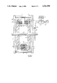
- FIG. 1 is an axial cross ection through a first embodiment of motor incorporating the invention
- FIG. 2 is a diagrammatic developed fragmentary view of part of the periphery of the motor of FIG. 1;
- FIG. 3 is a similar view of a second embodiment of motor incorporating the invention.
- FIG. 4 illustrates an alternative stator configuration
- FIG. 5 is a simplified electrical schematic diagram of the motor.
- a motor having a shaft 2 journalled in end plates 4, 6 of frames secured together by the bars 8 which also carry brackets 10 supporting cores 12 of stator coils 14 located between rotor discs 16 secured to the shaft 2.
- a tachometer is provided, typically consisting of a slotted disc 18 secured to the shaft 2 and an optical sensor 20, comprising light emitting and light sensitive diodes on opposite sides of the disc 18, is mounted on the end plate 6, the sensor 20 being connected to a control unit 22 to transmit thereto data as to the angular position of the shaft.
- the control unit controls the supply of energy from a direct current power supply 24 to the coils 14, and the transfer of energy between the coils and energy storage devices 26, typically capacitors, generally in the manner described in my U.S. Pat.
- stator coils In practice it is preferred for the stator coils to comprise bifilar windings 14a, 14b which are energized alternately in opposite senses so as toprovide alternating polarities at poles of the cores 12 and thus double the number of impulses applied to the rotor discs during a single revolution, as discussed further below.
- the cores 12 are of H configuration, with the cross bars 28 of the H's extending peripherally and the uprights 30 parallel to the axis of the motor towards the rotor discs.
- the coils 14a, 14b are bifilar wound on the cross bars 28, so that the uprights provide pole pieces adjacent the rotors.
- Each upright 30 provides two pole pieces 32 having the same polarity and a polarity opposite to that of the pole pieces 334 provided by the other upright 30.
- the cores 12 are formed from a stack of soft magnetic H-shaped laminations 36.
- the cores 12 are connected into a ring by further cross bars 28, and the coils 14a and 14b are wound on alternate cross bars 28.
- the cores may be assembled from T-shaped laminations, and the arrangement may assist in maximizing the usage of available space by the cores and windings.
- a coil 14a or 14b when energized will magnetize its associated core so as to provide north poles at one of the pairs of pole pieces 32, 34 and south poles at the other pair.
- the FIG. 3 embodiment will provide a similar effect in relation to the pole pieces adjacent an energized winding 14a or 14b.
- the rotor discs 16 are formed largely of non-magnetic material such as laminated fabric reinforced synthetic plastic of suitable strength. Metals such as aluminum may also be used, but care must then be taken to minimize losses due to eddy currents.
- High tenacity permanent magnets 38, 40 are located in pockets arranged in a ring near the periphery of each rotor, with their magnetic axis extending parallel to the axis of the motor, the magnets 38 having their north poles facing inwards and the magnets 40 having their south poles facing inwards.
- soft iron bridge pieces arranged as segments or a continuous ring 42 may be provided within the rotor outward of the magnets.
- the magnets 38, 40 in the two rotor discs are arranged so that like poles face one another.
- the motor described so far has but a single ring of cores 12 and windings 14, but in practice it will often be advantageous to use a plurality of rings of cores and windings, each separated by a rotor disc 16, as shown in FIG. 4. With such an arrangement, the number of rotor discs will exceed by one the number of rings of cores and windings. Whilst the intermediate rotor discs could be formed by two discs as already described mounted back to back, it may also be advantageous to make use of the opposite poles of the magnets 38, 40, the bridge pieces 42 being omitted. This requires either an offset equal to the pitch of the pole pieces 32, 34 between the cores 12 in each ring, or a reversal in the functions of the windings 14a, 14b.
- the construction lends itself to a modular structure by which a compact motor of any desired power output may be produced. If back to back discs are used, timing of the energization of the coils in different sections of the motor may be varied to increase the smoothness of operation.
- FIG. 5 A simplified schematic diagram of the coils 14 and 14b, capacitors CA and CB forming the energy storage devices 26, and parts of the control unit 22, is shown in FIG. 5.
- phase A windings are all connected in parallel
- phase B windings are all connected in parallel
- two identical control circuits being provided, one for each phase.
- parallel connection of the windings is shown, serial connection or a combination of serial and parallel connection could be used.
- a direct current supply to the motor from the power supply 24 is connected between the terminal marked +, and ground.
- phase A control circuit In the phase A control circuit, and assuming a positive to negative current flow convention, a circuit extends between the supply terminals via a diode D1A, the windings of phase A, a diode D2A, and a triple Darlington transistor combination TR1A. Current can only flow in this circuit when the transistor combinationis switched on by a signal A1 applied to the base of the input transistor, and then only provided that diode D1A is forward biased, i.e. the potential at the marked ends of the phase A windings is less than that of the supply potential, provided that the potential at the marked ends of the windings is greater than that at the unmarked ends, and provided that diode D2A is forward biased, i.e.
- the potential at the unmarked ends of the windings is above ground potential.
- TR1A is turned on and the above conditions are met, then current flows through the phase A windings, building up at a rate determined by the inductance of the windings which itself will incease as the magnetic circuits through the windings approach a minimum reluctance condition.
- the transistor combination TR1A is switched off and the current flowing in the coils finds an alternative return path through a further diode D3A and a capacitor CA, the capacitor CA forming with the coils a resonant circuit having a period dependent upon the value of CA and the inductance of the parallel connected windings.
- the magnetic energy is converted and transferred as electrical energy to the capacitor, the charging current through which passes to ground and thence via the supply and the diode D1A to complete the circuit.
- the oscillatory cycle reaches a point at which energy ceases to be transferred to the capacitor, the charge on the latter is retained by the diode D3A which prevents reverse current flow and cuts off the oscillation.
- the potential at the unmarked ends of the windings, and hence on the capacitor rises substantially above the supply potential.
- a thyristor SCRA is connected between the hot plate of the capacitor CA and the marked ends of the windings, and is triggered on by a suitable signal 2A applied simultaneously with application of a turn-on signal 1A to the transistor combination TR1A, thus completing a current path from the hot plate of the capacitor, through the windings, the diode D2A and the transistor TR1A to ground and thus the grounded plate of the capacitor.
- diode D1A Since the hot plate of capacitor CA will initially have a substantially higher potential than the supply, diode D1A will be reverse biased and current will not pass from the supply until and unless the potential at the junction of thyristor SCRA and diode D1A drops below the supply potential at which point current will flow from the supply through the diode rather than from the capacitor through the thyristor and the latter will turn itself off.
- control circuit associated with the windings of phase B operates similarly, similar reference indicia being used with a B suffix rather than an A suffix.
- the control signals 1A, 2A, 1B, 2B may be generated in control unit 22 in any way suited to the application of the motor.
- the sensor 20 provides signals which are amplified, shaped and phase shifted to form control signals, the signals also being compared with a reference signal representing a desired speed of the motor, with the control signals being modified accordingly. Under over-run conditions, energy may be withdrawn from the capacitors CA and CB and recycled to the supply or otherwise utilized so as to provide a more rapid reduction in speed of the motor.
- the magnetic circuits are now in a near maximum reluctance condition.
- the rotors 16 will therefore move to the right (as seen in FIG. 1) towards a minimum reluctance position with the magnets 38 opposite the pole pieces 34, and the magnets 40 opposite the pole pieces 32.
- the windings 14a are de-energized, and the magnetic field in the cores 12 is collapsed as previously described.
- the windings 14b are energized so as to reverse the polarization of the pole pieces and again urge the rotors to the right.
- the length and timing of the energization of the windings will depend on the power input needed to accelerate or maintain the speed of the motor, so as to provide most effective use of the magnetic impulses applied to the rotor by each energization of the windings. Operation of the embodiments of FIGS. 3 and 4 is similar.
- Proper starting of the motor can be assured in various ways, depending on the application. If the motor is exactly in a minimum reluctance position on starting, there may be an uncertainty as to the initial direction of motion. This may be prevented by means ensuring an initial mechanical or electrical assymmetry, for example by preventing the motor from coming to rest in a minimum reluctance position through the use of a ratchet and pawl device, or by providing some means to provide a starting impulse in the proper direction.
Landscapes
- Engineering & Computer Science (AREA)
- Power Engineering (AREA)
- Synchronous Machinery (AREA)
- Control Of Electric Motors In General (AREA)
Priority Applications (3)
| Application Number | Priority Date | Filing Date | Title |
|---|---|---|---|
| US07/077,412 US4761590A (en) | 1987-07-20 | 1987-07-20 | Electric motor |
| CA000572579A CA1284518C (fr) | 1987-07-20 | 1988-07-20 | Moteur a reluctance a noyaux statoriques en forme de h |
| GB8818274A GB2221579B (en) | 1987-07-20 | 1988-08-01 | Stator core arrangement for an electric motor |
Applications Claiming Priority (1)
| Application Number | Priority Date | Filing Date | Title |
|---|---|---|---|
| US07/077,412 US4761590A (en) | 1987-07-20 | 1987-07-20 | Electric motor |
Publications (1)
| Publication Number | Publication Date |
|---|---|
| US4761590A true US4761590A (en) | 1988-08-02 |
Family
ID=22137898
Family Applications (1)
| Application Number | Title | Priority Date | Filing Date |
|---|---|---|---|
| US07/077,412 Expired - Fee Related US4761590A (en) | 1987-07-20 | 1987-07-20 | Electric motor |
Country Status (3)
| Country | Link |
|---|---|
| US (1) | US4761590A (fr) |
| CA (1) | CA1284518C (fr) |
| GB (1) | GB2221579B (fr) |
Cited By (50)
| Publication number | Priority date | Publication date | Assignee | Title |
|---|---|---|---|---|
| US4862044A (en) * | 1987-03-25 | 1989-08-29 | Kabushiki Kaisha Yaskawa Denki Seisakusho | Method for adjusting encoder in a brushless motor-encoder combination |
| US4996457A (en) * | 1990-03-28 | 1991-02-26 | The United States Of America As Represented By The United States Department Of Energy | Ultra-high speed permanent magnet axial gap alternator with multiple stators |
| US5184040A (en) * | 1989-09-04 | 1993-02-02 | Lim Jong H | Electric power generators having like numbers of magnets and coils |
| US5227702A (en) * | 1991-09-19 | 1993-07-13 | Nahirney Peter M | Direct current motor utilizing back electromotive force |
| US5229677A (en) * | 1991-09-18 | 1993-07-20 | Newport News Shipbuilding And Dry Dock Company | Electric propulsion motor for marine vehicles |
| US5481143A (en) * | 1993-11-15 | 1996-01-02 | Burdick; Brian K. | Self starting brushless d.c. motor |
| US5905366A (en) * | 1995-11-23 | 1999-05-18 | Switched Reluctance Drives Limited | Method and apparatus for powering an electrical circuit using an isolated winding |
| EP0896415A4 (fr) * | 1997-01-24 | 2001-12-12 | Shigeaki Hayasaka | Machine dynamoelectrique ainsi que generateur et moteur l'utilisant |
| US6392370B1 (en) | 2000-01-13 | 2002-05-21 | Bedini Technology, Inc. | Device and method of a back EMF permanent electromagnetic motor generator |
| EP0862809B1 (fr) * | 1995-11-21 | 2002-07-31 | Itt Automotive Electrical Systems, Inc. | Stator a enroulement externe avec transition magnetique amrlioree |
| GB2338840B (en) * | 1998-04-16 | 2003-07-09 | Snr John Patrick Ettridge | An Electrical Machine |
| WO2003094328A1 (fr) * | 2002-04-30 | 2003-11-13 | Wavecrest Laboratories Llc | Moteur electrique rotatif pourvu de trajets de flux dans des entrefers a la fois radiaux et axiaux entre des segments de stator et de rotor |
| WO2003094327A1 (fr) * | 2002-04-30 | 2003-11-13 | Wavecrest Laboratories Llc | Moteur electrique rotatif avec segments de stator et de rotor separes par au moins deux entrefers |
| US20040232704A1 (en) * | 2001-09-13 | 2004-11-25 | Matteo Casazza | Wind power generator |
| US20060001269A1 (en) * | 2004-06-30 | 2006-01-05 | Jansen Patrick L | Electrical machine with double-sided rotor |
| EP1641101A1 (fr) * | 2004-09-27 | 2006-03-29 | General Electric Company | Machine électrique avec stator double-face |
| US20060066110A1 (en) * | 2004-09-27 | 2006-03-30 | General Electric Company | Electrical machine with double-sided lamination stack |
| US20070103027A1 (en) * | 2004-09-27 | 2007-05-10 | Jansen Patrick L | Electrical machine with double-sided lamination stack |
| US20070108865A1 (en) * | 2004-09-27 | 2007-05-17 | Jansen Patrick L | Electrical machine with double-sided stator |
| WO2008122437A3 (fr) * | 2007-04-10 | 2009-03-19 | Klaus Thissen | Convertisseur destiné à convertir de l'énergie magnétique en énergie cinétique et/ou en énergie électrique et procédé destiné à convertir de l'énergie magnétique en énergie cinétique et/ou en énergie électrique au |
| CN100544168C (zh) * | 2003-02-26 | 2009-09-23 | 富士通将军股份有限公司 | 轴向空隙型电动机 |
| US20100026010A1 (en) * | 2006-12-22 | 2010-02-04 | High Technology Investments B.V. | Multiple generator wind turbine |
| US7808149B2 (en) | 2004-09-20 | 2010-10-05 | Wilic S.Ar.L. | Generator/electric motor, in particular for wind power plants, cable controlled plants or for hydraulic plants |
| US20110089872A1 (en) * | 2009-12-22 | 2011-04-21 | Kress Motors LLC | Dipolar axial compression permanent magnet motor |
| US7936102B2 (en) | 2005-11-29 | 2011-05-03 | Wilic S.Ar.L | Magnet holder for permanent magnet rotors of rotating machines |
| US7946591B2 (en) | 2005-09-21 | 2011-05-24 | Wilic S.Ar.L. | Combined labyrinth seal and screw-type gasket bearing sealing arrangement |
| US8120198B2 (en) | 2008-07-23 | 2012-02-21 | Wilic S.Ar.L. | Wind power turbine |
| US8272822B2 (en) | 2009-01-30 | 2012-09-25 | Wilic S.Ar.L. | Wind power turbine blade packing and packing method |
| US8274170B2 (en) | 2009-04-09 | 2012-09-25 | Willic S.A.R.L. | Wind power turbine including a cable bundle guide device |
| US8310122B2 (en) | 2005-11-29 | 2012-11-13 | Wilic S.A.R.L. | Core plate stack assembly for permanent magnet rotor or rotating machines |
| US8319362B2 (en) | 2008-11-12 | 2012-11-27 | Wilic S.Ar.L. | Wind power turbine with a cooling system |
| WO2012062710A3 (fr) * | 2010-11-10 | 2012-12-20 | Steffen Söhner Gmbh | Moteur électrique à entrefer plan et vélo électrique ou vélo à assistance électrique équipé d'un moteur électrique à entrefer plan |
| US8358189B2 (en) | 2009-08-07 | 2013-01-22 | Willic S.Ar.L. | Method and apparatus for activating an electric machine, and electric machine |
| US8410623B2 (en) | 2009-06-10 | 2013-04-02 | Wilic S. AR. L. | Wind power electricity generating system and relative control method |
| US8492919B2 (en) | 2008-06-19 | 2013-07-23 | Wilic S.Ar.L. | Wind power generator equipped with a cooling system |
| US8541902B2 (en) | 2010-02-04 | 2013-09-24 | Wilic S.Ar.L. | Wind power turbine electric generator cooling system and method and wind power turbine comprising such a cooling system |
| US8618689B2 (en) | 2009-11-23 | 2013-12-31 | Wilic S.Ar.L. | Wind power turbine for generating electric energy |
| US8659867B2 (en) | 2009-04-29 | 2014-02-25 | Wilic S.A.R.L. | Wind power system for generating electric energy |
| US8669685B2 (en) | 2008-11-13 | 2014-03-11 | Wilic S.Ar.L. | Wind power turbine for producing electric energy |
| EP1976102A3 (fr) * | 2007-03-26 | 2014-12-10 | Robert Bosch Gmbh | Machine électrique homopolaire |
| US8937397B2 (en) | 2010-03-30 | 2015-01-20 | Wilic S.A.R.L. | Wind power turbine and method of removing a bearing from a wind power turbine |
| US8937398B2 (en) | 2011-03-10 | 2015-01-20 | Wilic S.Ar.L. | Wind turbine rotary electric machine |
| US8957555B2 (en) | 2011-03-10 | 2015-02-17 | Wilic S.Ar.L. | Wind turbine rotary electric machine |
| US8975770B2 (en) | 2010-04-22 | 2015-03-10 | Wilic S.Ar.L. | Wind power turbine electric generator and wind power turbine equipped with an electric generator |
| US9006918B2 (en) | 2011-03-10 | 2015-04-14 | Wilic S.A.R.L. | Wind turbine |
| US20150207394A1 (en) * | 2010-04-19 | 2015-07-23 | Robert V. Albertson | Magnet power transmission |
| US9190949B1 (en) | 2010-12-22 | 2015-11-17 | Kress Motors, LLC | Dipolar axial compression magnet motor |
| US9467009B2 (en) | 2009-12-22 | 2016-10-11 | Kress Motors, LLC | Dipolar transverse flux electric machine |
| DE102019000724A1 (de) | 2019-01-30 | 2020-07-30 | Edna Evangelista Marques da Silva | Konstruktion, Aufbau, Applikationen und Steuerungsverfahren von elektrischen Maschinen, Verwendung von elektrisch erregten Sekundärteilen in Linearmotoren, Levitation, magnetische Lagerung und Aufbau von elektrischen Direktmaschinen |
| DE102021002106A1 (de) | 2021-04-21 | 2022-10-27 | Edna Evangelista Marques da Silva | Konstruktion und Aufbau von rotatorischen elektrischen Direktmaschinen mit Scheibenläufer und kreissegmentförmigen elektrischen Direktmaschinen zur Erhöhung der Leistungsdichte |
Families Citing this family (7)
| Publication number | Priority date | Publication date | Assignee | Title |
|---|---|---|---|---|
| KR100226412B1 (ko) * | 1996-11-30 | 1999-10-15 | 배길성 | 스위치드릴럭턴스모터용 회전자의 위치검출장치 |
| GB2379093A (en) * | 2001-08-22 | 2003-02-26 | Chia-Hao Fan | Side rotation (axial) type motor/dynamo |
| RU2264683C2 (ru) * | 2003-01-31 | 2005-11-20 | Пятин Викентий Васильевич | Электромагнитное устройство |
| WO2004073143A1 (fr) * | 2003-02-11 | 2004-08-26 | Randall Family Trust | Machine electrique a entrefer axial |
| DE20314652U1 (de) * | 2003-09-22 | 2004-08-26 | Minebea Co., Ltd. | Motor mit axialem Magnetfluß und ringförmigem Stator |
| ATE350802T1 (de) * | 2003-10-18 | 2007-01-15 | Malik Saad Zaghlool Awad | Hochleistungs-flach-dreiphasen-stromgenerator |
| RU2387064C1 (ru) * | 2008-09-15 | 2010-04-20 | Викентий Васильевич Пятин | Электромагнитное устройство |
Citations (7)
| Publication number | Priority date | Publication date | Assignee | Title |
|---|---|---|---|---|
| US3534204A (en) * | 1967-10-03 | 1970-10-13 | Bosch Gmbh Robert | Alternating current generator |
| US3983430A (en) * | 1974-04-24 | 1976-09-28 | Howard Gerald T | Electric generator |
| US4025831A (en) * | 1975-02-18 | 1977-05-24 | Webb Robert L | Brushless direct current motor |
| US4095150A (en) * | 1976-07-12 | 1978-06-13 | Karlheinz Senckel | Two-phase asynchronous motor |
| US4318038A (en) * | 1978-11-15 | 1982-03-02 | Nippon Electric Co., Ltd. | Moving-coil linear motor |
| US4460855A (en) * | 1980-05-19 | 1984-07-17 | Kelly H P G | Linear motor |
| US4584506A (en) * | 1984-11-23 | 1986-04-22 | Polestar Magnetronics Inc. | Reluctance motor with electronically controlled stator windings |
-
1987
- 1987-07-20 US US07/077,412 patent/US4761590A/en not_active Expired - Fee Related
-
1988
- 1988-07-20 CA CA000572579A patent/CA1284518C/fr not_active Expired - Lifetime
- 1988-08-01 GB GB8818274A patent/GB2221579B/en not_active Expired - Fee Related
Patent Citations (7)
| Publication number | Priority date | Publication date | Assignee | Title |
|---|---|---|---|---|
| US3534204A (en) * | 1967-10-03 | 1970-10-13 | Bosch Gmbh Robert | Alternating current generator |
| US3983430A (en) * | 1974-04-24 | 1976-09-28 | Howard Gerald T | Electric generator |
| US4025831A (en) * | 1975-02-18 | 1977-05-24 | Webb Robert L | Brushless direct current motor |
| US4095150A (en) * | 1976-07-12 | 1978-06-13 | Karlheinz Senckel | Two-phase asynchronous motor |
| US4318038A (en) * | 1978-11-15 | 1982-03-02 | Nippon Electric Co., Ltd. | Moving-coil linear motor |
| US4460855A (en) * | 1980-05-19 | 1984-07-17 | Kelly H P G | Linear motor |
| US4584506A (en) * | 1984-11-23 | 1986-04-22 | Polestar Magnetronics Inc. | Reluctance motor with electronically controlled stator windings |
Non-Patent Citations (2)
| Title |
|---|
| `Switched Reluctance Motor Drive Systems ` Design Engineering, May 1984, pp. 74-75. |
| Switched Reluctance Motor Drive Systems Design Engineering, May 1984, pp. 74 75. * |
Cited By (79)
| Publication number | Priority date | Publication date | Assignee | Title |
|---|---|---|---|---|
| US4862044A (en) * | 1987-03-25 | 1989-08-29 | Kabushiki Kaisha Yaskawa Denki Seisakusho | Method for adjusting encoder in a brushless motor-encoder combination |
| US5184040A (en) * | 1989-09-04 | 1993-02-02 | Lim Jong H | Electric power generators having like numbers of magnets and coils |
| US4996457A (en) * | 1990-03-28 | 1991-02-26 | The United States Of America As Represented By The United States Department Of Energy | Ultra-high speed permanent magnet axial gap alternator with multiple stators |
| US5229677A (en) * | 1991-09-18 | 1993-07-20 | Newport News Shipbuilding And Dry Dock Company | Electric propulsion motor for marine vehicles |
| US5227702A (en) * | 1991-09-19 | 1993-07-13 | Nahirney Peter M | Direct current motor utilizing back electromotive force |
| US5481143A (en) * | 1993-11-15 | 1996-01-02 | Burdick; Brian K. | Self starting brushless d.c. motor |
| EP0862809B1 (fr) * | 1995-11-21 | 2002-07-31 | Itt Automotive Electrical Systems, Inc. | Stator a enroulement externe avec transition magnetique amrlioree |
| US5905366A (en) * | 1995-11-23 | 1999-05-18 | Switched Reluctance Drives Limited | Method and apparatus for powering an electrical circuit using an isolated winding |
| EP0896415A4 (fr) * | 1997-01-24 | 2001-12-12 | Shigeaki Hayasaka | Machine dynamoelectrique ainsi que generateur et moteur l'utilisant |
| GB2338840B (en) * | 1998-04-16 | 2003-07-09 | Snr John Patrick Ettridge | An Electrical Machine |
| US6392370B1 (en) | 2000-01-13 | 2002-05-21 | Bedini Technology, Inc. | Device and method of a back EMF permanent electromagnetic motor generator |
| US7109671B2 (en) | 2000-01-13 | 2006-09-19 | Energenx, Inc. | Device and method of a back EMF permanent electromagnetic motor generator |
| US7205678B2 (en) | 2001-09-13 | 2007-04-17 | Matteo Casazza | Wind power generator |
| US7687932B2 (en) | 2001-09-13 | 2010-03-30 | High Technology Investments B.V. | Wind power generator and bearing structure therefor |
| US20040232704A1 (en) * | 2001-09-13 | 2004-11-25 | Matteo Casazza | Wind power generator |
| US7385306B2 (en) | 2001-09-13 | 2008-06-10 | Matteo Casazza | wind power generator including blade arrangement |
| US7893555B2 (en) | 2001-09-13 | 2011-02-22 | Wilic S.Ar.L. | Wind power current generator |
| US7385305B2 (en) | 2001-09-13 | 2008-06-10 | Matteo Casazza | Wind power generator and bearing structure therefor |
| US20070222227A1 (en) * | 2001-09-13 | 2007-09-27 | High Technology Investments, Bv | Wind power generator including blade arrangement |
| US20070222226A1 (en) * | 2001-09-13 | 2007-09-27 | High Technology Investments, Bv | Wind power generator and bearing structure therefor |
| US20080315594A1 (en) * | 2001-09-13 | 2008-12-25 | High Technology Investments, Bv | Wind power generator and bearing structure therefor |
| US6891306B1 (en) | 2002-04-30 | 2005-05-10 | Wavecrest Laboratories, Llc. | Rotary electric motor having both radial and axial air gap flux paths between stator and rotor segments |
| US6791222B1 (en) | 2002-04-30 | 2004-09-14 | Wavecrest Laboratories, Llc | Rotary electric motor having at least two axially air gaps separating stator and rotor segments |
| WO2003094327A1 (fr) * | 2002-04-30 | 2003-11-13 | Wavecrest Laboratories Llc | Moteur electrique rotatif avec segments de stator et de rotor separes par au moins deux entrefers |
| WO2003094328A1 (fr) * | 2002-04-30 | 2003-11-13 | Wavecrest Laboratories Llc | Moteur electrique rotatif pourvu de trajets de flux dans des entrefers a la fois radiaux et axiaux entre des segments de stator et de rotor |
| CN101447701B (zh) * | 2003-02-26 | 2011-09-14 | 富士通将军股份有限公司 | 轴向空隙型电动机 |
| CN100544168C (zh) * | 2003-02-26 | 2009-09-23 | 富士通将军股份有限公司 | 轴向空隙型电动机 |
| US7154191B2 (en) | 2004-06-30 | 2006-12-26 | General Electric Company | Electrical machine with double-sided rotor |
| US20070281558A1 (en) * | 2004-06-30 | 2007-12-06 | Jansen Patrick L | Electrical machine with double-sided rotor |
| US7830063B2 (en) | 2004-06-30 | 2010-11-09 | General Electric Company | Electrical machine with double-sided rotor |
| US20060001269A1 (en) * | 2004-06-30 | 2006-01-05 | Jansen Patrick L | Electrical machine with double-sided rotor |
| US7808149B2 (en) | 2004-09-20 | 2010-10-05 | Wilic S.Ar.L. | Generator/electric motor, in particular for wind power plants, cable controlled plants or for hydraulic plants |
| US20060066110A1 (en) * | 2004-09-27 | 2006-03-30 | General Electric Company | Electrical machine with double-sided lamination stack |
| US7548008B2 (en) | 2004-09-27 | 2009-06-16 | General Electric Company | Electrical machine with double-sided lamination stack |
| US20070108865A1 (en) * | 2004-09-27 | 2007-05-17 | Jansen Patrick L | Electrical machine with double-sided stator |
| EP1641101A1 (fr) * | 2004-09-27 | 2006-03-29 | General Electric Company | Machine électrique avec stator double-face |
| US20070103027A1 (en) * | 2004-09-27 | 2007-05-10 | Jansen Patrick L | Electrical machine with double-sided lamination stack |
| US7154192B2 (en) | 2004-09-27 | 2006-12-26 | General Electric Company | Electrical machine with double-sided lamination stack |
| US7154193B2 (en) | 2004-09-27 | 2006-12-26 | General Electric Company | Electrical machine with double-sided stator |
| US7839048B2 (en) | 2004-09-27 | 2010-11-23 | General Electric Company | Electrical machine with double-sided stator |
| US20060071575A1 (en) * | 2004-09-27 | 2006-04-06 | General Electric Company | Electrical machine with double-sided stator |
| US7946591B2 (en) | 2005-09-21 | 2011-05-24 | Wilic S.Ar.L. | Combined labyrinth seal and screw-type gasket bearing sealing arrangement |
| US7936102B2 (en) | 2005-11-29 | 2011-05-03 | Wilic S.Ar.L | Magnet holder for permanent magnet rotors of rotating machines |
| US8310122B2 (en) | 2005-11-29 | 2012-11-13 | Wilic S.A.R.L. | Core plate stack assembly for permanent magnet rotor or rotating machines |
| US20100026010A1 (en) * | 2006-12-22 | 2010-02-04 | High Technology Investments B.V. | Multiple generator wind turbine |
| EP1976102A3 (fr) * | 2007-03-26 | 2014-12-10 | Robert Bosch Gmbh | Machine électrique homopolaire |
| WO2008122437A3 (fr) * | 2007-04-10 | 2009-03-19 | Klaus Thissen | Convertisseur destiné à convertir de l'énergie magnétique en énergie cinétique et/ou en énergie électrique et procédé destiné à convertir de l'énergie magnétique en énergie cinétique et/ou en énergie électrique au |
| US10505419B2 (en) | 2008-06-19 | 2019-12-10 | Windfin B.V. | Wind power generator equipped with a cooling system |
| US9312741B2 (en) | 2008-06-19 | 2016-04-12 | Windfin B.V. | Wind power generator equipped with a cooling system |
| US8492919B2 (en) | 2008-06-19 | 2013-07-23 | Wilic S.Ar.L. | Wind power generator equipped with a cooling system |
| US8120198B2 (en) | 2008-07-23 | 2012-02-21 | Wilic S.Ar.L. | Wind power turbine |
| US8319362B2 (en) | 2008-11-12 | 2012-11-27 | Wilic S.Ar.L. | Wind power turbine with a cooling system |
| US8669685B2 (en) | 2008-11-13 | 2014-03-11 | Wilic S.Ar.L. | Wind power turbine for producing electric energy |
| US8272822B2 (en) | 2009-01-30 | 2012-09-25 | Wilic S.Ar.L. | Wind power turbine blade packing and packing method |
| US8274170B2 (en) | 2009-04-09 | 2012-09-25 | Willic S.A.R.L. | Wind power turbine including a cable bundle guide device |
| US8659867B2 (en) | 2009-04-29 | 2014-02-25 | Wilic S.A.R.L. | Wind power system for generating electric energy |
| US8410623B2 (en) | 2009-06-10 | 2013-04-02 | Wilic S. AR. L. | Wind power electricity generating system and relative control method |
| US8358189B2 (en) | 2009-08-07 | 2013-01-22 | Willic S.Ar.L. | Method and apparatus for activating an electric machine, and electric machine |
| US8810347B2 (en) | 2009-08-07 | 2014-08-19 | Wilic S.Ar.L | Method and apparatus for activating an electric machine, and electric machine |
| US8618689B2 (en) | 2009-11-23 | 2013-12-31 | Wilic S.Ar.L. | Wind power turbine for generating electric energy |
| US20110089872A1 (en) * | 2009-12-22 | 2011-04-21 | Kress Motors LLC | Dipolar axial compression permanent magnet motor |
| CN102577031B (zh) * | 2009-12-22 | 2014-08-13 | 克雷斯发动机有限责任公司 | 双极轴向挤压永磁体电动机 |
| CN102577031A (zh) * | 2009-12-22 | 2012-07-11 | 克雷斯发动机有限责任公司 | 双极轴向挤压永磁体电动机 |
| US9467009B2 (en) | 2009-12-22 | 2016-10-11 | Kress Motors, LLC | Dipolar transverse flux electric machine |
| US8138696B2 (en) * | 2009-12-22 | 2012-03-20 | Kress Motors, LLC | Dipolar axial compression permanent magnet motor |
| US8541902B2 (en) | 2010-02-04 | 2013-09-24 | Wilic S.Ar.L. | Wind power turbine electric generator cooling system and method and wind power turbine comprising such a cooling system |
| US8937397B2 (en) | 2010-03-30 | 2015-01-20 | Wilic S.A.R.L. | Wind power turbine and method of removing a bearing from a wind power turbine |
| US20150207394A1 (en) * | 2010-04-19 | 2015-07-23 | Robert V. Albertson | Magnet power transmission |
| US9559576B2 (en) * | 2010-04-19 | 2017-01-31 | Mag-Trans Corporation | Magnet power transmission |
| US8975770B2 (en) | 2010-04-22 | 2015-03-10 | Wilic S.Ar.L. | Wind power turbine electric generator and wind power turbine equipped with an electric generator |
| US9438092B2 (en) | 2010-11-10 | 2016-09-06 | Binova Gmbh | Electric disk rotor motor and electric bicycle or pedelec comprising a disk rotor motor |
| DE102010060482B4 (de) * | 2010-11-10 | 2017-07-13 | Binova Gmbh | Elektrischer Scheibenläufermotor und Elektrofahrrad oder Pedelec mit einem Scheibenläufermotor |
| WO2012062710A3 (fr) * | 2010-11-10 | 2012-12-20 | Steffen Söhner Gmbh | Moteur électrique à entrefer plan et vélo électrique ou vélo à assistance électrique équipé d'un moteur électrique à entrefer plan |
| US9190949B1 (en) | 2010-12-22 | 2015-11-17 | Kress Motors, LLC | Dipolar axial compression magnet motor |
| US9006918B2 (en) | 2011-03-10 | 2015-04-14 | Wilic S.A.R.L. | Wind turbine |
| US8957555B2 (en) | 2011-03-10 | 2015-02-17 | Wilic S.Ar.L. | Wind turbine rotary electric machine |
| US8937398B2 (en) | 2011-03-10 | 2015-01-20 | Wilic S.Ar.L. | Wind turbine rotary electric machine |
| DE102019000724A1 (de) | 2019-01-30 | 2020-07-30 | Edna Evangelista Marques da Silva | Konstruktion, Aufbau, Applikationen und Steuerungsverfahren von elektrischen Maschinen, Verwendung von elektrisch erregten Sekundärteilen in Linearmotoren, Levitation, magnetische Lagerung und Aufbau von elektrischen Direktmaschinen |
| DE102021002106A1 (de) | 2021-04-21 | 2022-10-27 | Edna Evangelista Marques da Silva | Konstruktion und Aufbau von rotatorischen elektrischen Direktmaschinen mit Scheibenläufer und kreissegmentförmigen elektrischen Direktmaschinen zur Erhöhung der Leistungsdichte |
Also Published As
| Publication number | Publication date |
|---|---|
| GB2221579A (en) | 1990-02-07 |
| CA1284518C (fr) | 1991-05-28 |
| GB8818274D0 (en) | 1988-09-07 |
| GB2221579B (en) | 1993-03-31 |
Similar Documents
| Publication | Publication Date | Title |
|---|---|---|
| CA1284518C (fr) | Moteur a reluctance a noyaux statoriques en forme de h | |
| JP2832307B2 (ja) | 電動機 | |
| US4687961A (en) | Polyphase DC motor with sensor poles | |
| US3873897A (en) | Collector-less D-C motor | |
| US5329195A (en) | Sensor motor | |
| US4450396A (en) | Electrically controlled synchronous machine | |
| US4874975A (en) | Brushless DC motor | |
| US4794286A (en) | Variable reluctance stepper motor | |
| EP0559818B1 (fr) | Moteur polyphase a reluctance et a commutation | |
| US5672925A (en) | Doubly salient variable reluctance machine with stationary permanent magnets or auxiliary field windings | |
| US6121705A (en) | Alternating pole AC motor/generator with two inner rotating rotors and an external static stator | |
| US5825112A (en) | Doubly salient motor with stationary permanent magnets | |
| US4584506A (en) | Reluctance motor with electronically controlled stator windings | |
| US4081726A (en) | Electric motor | |
| US4276490A (en) | Brushless DC motor with rare-earth magnet rotor and segmented stator | |
| US4275339A (en) | Bifilar brushless DC motor | |
| KR970060638A (ko) | 브러시리스 직류모터 | |
| US7432623B2 (en) | Brushless electromechanical machine | |
| WO1996018232A1 (fr) | Moteur polyphase a enroulement auxiliaire et a reluctance variable | |
| CA1260522A (fr) | Moteur c.c. sans balais | |
| MY108313A (en) | Brushless induction synchronous motor with two stators. | |
| EP0431178B1 (fr) | Machine synchrone | |
| US7276831B1 (en) | Split-pole field-match motor | |
| EP0242456B1 (fr) | Moteur à réluctance variable avec les enroulements de stator à commutation électronique | |
| EP0240204A2 (fr) | Moteur pas à pas avec réluctance variable |
Legal Events
| Date | Code | Title | Description |
|---|---|---|---|
| AS | Assignment |
Owner name: POLESTAR MAGNETRONICS INC., 463 MCNICOLL AVENUE, W Free format text: ASSIGNMENT OF ASSIGNORS INTEREST.;ASSIGNOR:KASZMAN, JOHN;REEL/FRAME:004796/0074 Effective date: 19870715 Owner name: POLESTAR MAGNETRONICS INC., 463 MCNICOLL AVENUE, W Free format text: ASSIGNMENT OF ASSIGNORS INTEREST;ASSIGNOR:KASZMAN, JOHN;REEL/FRAME:004796/0074 Effective date: 19870715 |
|
| FEPP | Fee payment procedure |
Free format text: PAYOR NUMBER ASSIGNED (ORIGINAL EVENT CODE: ASPN); ENTITY STATUS OF PATENT OWNER: SMALL ENTITY |
|
| FPAY | Fee payment |
Year of fee payment: 4 |
|
| REMI | Maintenance fee reminder mailed | ||
| LAPS | Lapse for failure to pay maintenance fees | ||
| FP | Lapsed due to failure to pay maintenance fee |
Effective date: 19960807 |
|
| STCH | Information on status: patent discontinuation |
Free format text: PATENT EXPIRED DUE TO NONPAYMENT OF MAINTENANCE FEES UNDER 37 CFR 1.362 |