US4776665A - Metal-free, self-bearing optical cable for high-tension overhead lines - Google Patents
Metal-free, self-bearing optical cable for high-tension overhead lines Download PDFInfo
- Publication number
- US4776665A US4776665A US06/886,830 US88683086A US4776665A US 4776665 A US4776665 A US 4776665A US 88683086 A US88683086 A US 88683086A US 4776665 A US4776665 A US 4776665A
- Authority
- US
- United States
- Prior art keywords
- cable
- self
- free
- metal
- core
- Prior art date
- Legal status (The legal status is an assumption and is not a legal conclusion. Google has not performed a legal analysis and makes no representation as to the accuracy of the status listed.)
- Expired - Lifetime
Links
- 230000003287 optical effect Effects 0.000 title claims abstract description 46
- 239000004020 conductor Substances 0.000 claims abstract description 11
- 238000005253 cladding Methods 0.000 claims description 53
- 239000000463 material Substances 0.000 claims description 10
- 239000011521 glass Substances 0.000 claims description 9
- 239000004033 plastic Substances 0.000 claims description 6
- 229920003023 plastic Polymers 0.000 claims description 6
- 239000004952 Polyamide Substances 0.000 claims description 5
- WNROFYMDJYEPJX-UHFFFAOYSA-K aluminium hydroxide Chemical compound [OH-].[OH-].[OH-].[Al+3] WNROFYMDJYEPJX-UHFFFAOYSA-K 0.000 claims description 5
- 229920002647 polyamide Polymers 0.000 claims description 5
- 150000001875 compounds Chemical class 0.000 claims description 3
- 239000000843 powder Substances 0.000 claims description 3
- 238000007789 sealing Methods 0.000 claims description 3
- 239000011358 absorbing material Substances 0.000 claims description 2
- 229920000728 polyester Polymers 0.000 claims description 2
- 230000008961 swelling Effects 0.000 claims description 2
- 239000000654 additive Substances 0.000 claims 2
- 230000000996 additive effect Effects 0.000 claims 2
- 229910052751 metal Inorganic materials 0.000 abstract description 3
- 239000002184 metal Substances 0.000 abstract description 3
- 239000011162 core material Substances 0.000 description 22
- 230000000694 effects Effects 0.000 description 6
- 238000011109 contamination Methods 0.000 description 5
- 238000010586 diagram Methods 0.000 description 5
- 239000013256 coordination polymer Substances 0.000 description 4
- 238000010521 absorption reaction Methods 0.000 description 3
- 239000000203 mixture Substances 0.000 description 3
- 238000000576 coating method Methods 0.000 description 2
- 230000006378 damage Effects 0.000 description 2
- 230000001419 dependent effect Effects 0.000 description 2
- 230000004048 modification Effects 0.000 description 2
- 238000012986 modification Methods 0.000 description 2
- 229920002635 polyurethane Polymers 0.000 description 2
- 239000004814 polyurethane Substances 0.000 description 2
- 230000009467 reduction Effects 0.000 description 2
- 230000035939 shock Effects 0.000 description 2
- XLYOFNOQVPJJNP-UHFFFAOYSA-N water Substances O XLYOFNOQVPJJNP-UHFFFAOYSA-N 0.000 description 2
- 239000005995 Aluminium silicate Substances 0.000 description 1
- 238000009825 accumulation Methods 0.000 description 1
- 230000006978 adaptation Effects 0.000 description 1
- 235000012211 aluminium silicate Nutrition 0.000 description 1
- 230000003466 anti-cipated effect Effects 0.000 description 1
- 230000015556 catabolic process Effects 0.000 description 1
- 239000011248 coating agent Substances 0.000 description 1
- 239000000470 constituent Substances 0.000 description 1
- 230000008878 coupling Effects 0.000 description 1
- 238000010168 coupling process Methods 0.000 description 1
- 238000005859 coupling reaction Methods 0.000 description 1
- 230000003111 delayed effect Effects 0.000 description 1
- 230000006866 deterioration Effects 0.000 description 1
- 230000009970 fire resistant effect Effects 0.000 description 1
- 230000006870 function Effects 0.000 description 1
- 231100001261 hazardous Toxicity 0.000 description 1
- 239000011810 insulating material Substances 0.000 description 1
- 238000009413 insulation Methods 0.000 description 1
- NLYAJNPCOHFWQQ-UHFFFAOYSA-N kaolin Chemical compound O.O.O=[Al]O[Si](=O)O[Si](=O)O[Al]=O NLYAJNPCOHFWQQ-UHFFFAOYSA-N 0.000 description 1
- 230000009972 noncorrosive effect Effects 0.000 description 1
- 230000008447 perception Effects 0.000 description 1
- 229920000515 polycarbonate Polymers 0.000 description 1
- 239000004417 polycarbonate Substances 0.000 description 1
- 229920000098 polyolefin Polymers 0.000 description 1
- 229920006395 saturated elastomer Polymers 0.000 description 1
- 239000000454 talc Substances 0.000 description 1
- 229910052623 talc Inorganic materials 0.000 description 1
- 230000007704 transition Effects 0.000 description 1
- 238000004804 winding Methods 0.000 description 1
Images


Classifications
-
- G—PHYSICS
- G02—OPTICS
- G02B—OPTICAL ELEMENTS, SYSTEMS OR APPARATUS
- G02B6/00—Light guides; Structural details of arrangements comprising light guides and other optical elements, e.g. couplings
- G02B6/44—Mechanical structures for providing tensile strength and external protection for fibres, e.g. optical transmission cables
- G02B6/4401—Optical cables
- G02B6/4415—Cables for special applications
- G02B6/4416—Heterogeneous cables
- G02B6/4422—Heterogeneous cables of the overhead type
-
- G—PHYSICS
- G02—OPTICS
- G02B—OPTICAL ELEMENTS, SYSTEMS OR APPARATUS
- G02B6/00—Light guides; Structural details of arrangements comprising light guides and other optical elements, e.g. couplings
- G02B6/44—Mechanical structures for providing tensile strength and external protection for fibres, e.g. optical transmission cables
- G02B6/4401—Optical cables
- G02B6/4415—Cables for special applications
- G02B6/4416—Heterogeneous cables
-
- G—PHYSICS
- G02—OPTICS
- G02B—OPTICAL ELEMENTS, SYSTEMS OR APPARATUS
- G02B6/00—Light guides; Structural details of arrangements comprising light guides and other optical elements, e.g. couplings
- G02B6/44—Mechanical structures for providing tensile strength and external protection for fibres, e.g. optical transmission cables
- G02B6/4401—Optical cables
- G02B6/4415—Cables for special applications
- G02B6/4416—Heterogeneous cables
- G02B6/4417—High voltage aspects, e.g. in cladding
- G02B6/4419—Preventing corona discharge
Definitions
- the present invention relates to a metal-free, self-bearing optical cable composed of a cable core and cable cladding for use as an overhead cable in the field region of phase wires of a high-tension overhead line.
- Optical cables are frequently laid in the region of high-tension overhead lines in one of two fundamentally different arrangements.
- the optical cables are integrated in or clipped to phase or guard wires.
- the optical cables are constructed as self-bearing structures and are laid, or strung, in the field region, in other words, between or under the phase wires of a high-tension line.
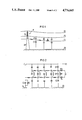
- the fundamental structure of a self-bearing optical cable in the second configuration and the capacitive couplings derive therefrom are shown schematically in FIG. 1.
- a single phase high-tension overhead line HF is shown, wherein a metal-free, self-bearing optical cable OK is strung in the field region and is held by a cross arm TR of a lattice tower GM.
- a guard wire referenced ES and a phase wire referenced PS are also shown.
- the jacket surface of the optical cable OK can be simulated by an equivalent circuit diagram formed of series resistances RL.
- Shunt capacitances CE extend between the optical cable OK and the guard wires ES, as well as between the optical cable OK and ground ED.
- Equivalent capacitances CP extend between the optical cable OK and the phase wire PS.
- the illustrated equivalent circuit diagram also applies by analogy to a multi-phase high-tension line, wherein all of the phase conductors are shown united in an equivalent phase conductor.
- the claddings of "fully dielectric cables” can be damaged or destroyed due to partial discharge events as a result of voltages appearing at the cable cladding, particularly for high-tension networks, such as those greater than or equal to 110 kV.
- the cable surface is effected by humidity and deposits, such as dirt, having the surface resistance RL, and as a result, assumes a voltage defined by the shunt capacitances CE and the effective partial capacitances CP in equilibrium when at an adequate distance from the grounded towers GM. In a worst case, the surface voltage at the optical cable can equal up to 50% of the phase voltage.
- Part of the resulting charging current flows off in the direction of the grounded tower GM via the surface resistance RL.
- the flowing current causes arc-overs and tracking currents of sufficient magnitude to break down the material of the outside cladding of the optical cable OK as a result of nonuniform resistances in the humidity film or in the contamination deposits.
- all transition conditions between damp and dry surfaces and/or between more or less contaminated surfaces are particularly critical.
- An object of the present invention is to reduce and possibly avoid stressing of an optical cable as caused by tracking currents and arc-overs for metal-free cables of the type described above. This and other objects are achieved in accordance with the teachings of the present invention by providing a cable core formed of weakly electrically conductive material having a resistivity of between 10 5 ⁇ cm and 10 10 ⁇ cm.
- the hazardous nonuniform resistance at the surface of the optical cable is to a large extent capacitively ohmically bridged.
- arc-overs and tracking currents are sufficiently disabled or avoided to avoid the undesired breakdown or destruction of the material of the optical cable.
- a preferred embodiment also includes weakly conductive elements in the cable cladding.
- FIG. 1 shows a high-tension overhead line and self-bearing optical cable, as well as an equivalent electrical circuit
- FIG. 2 is an equivalent circuit diagram of an optical cable of the present invention
- FIG. 3 is a lateral cross-section of the cable of the present invention.
- FIG. 4 is a diagrammatic side elevation showing the guying of the present optical cable at a tower.
- FIG. 5 is an elevation, partially in cross-section, showing the grounding of the present cable core.
- an equivalent circuit diagram as shown in FIG. 2 is obtained when both cable cladding and cable core are formed of slightly electrically conductive materials according to the present invention.
- Equivalent resistances and capacitances are also obtained.
- shunt capacitances CP existing between the surface of cable cladding KM of the optical cable OK and the phase wire PS
- CE existing between the cable OK and the ground ED
- yet another capacitance CM arises between the surface of the cable cladding KM and a cable core KS, as shown in FIG. 3.
- the capacitance CM known as the cladding capacitance, is more than 100 times greater than the partial capacitances CP and CE as a result of the compact physical structure of the optical cable OK.
- the surface resistances ROL on the cable cladding KM that are formed by the degree of contamination and dampness on an outside cladding layer MA1 of the cladding KM are potentialcontrolled in accordance with the present invention by an inside series resistance RIL formed by the slightly conductive cable core KS.
- the surface resistance ROL also called the outside series resistance, depends in amplitude on the exterior condition of the cable cladding KM, and in fact does not become completely without effect. However, the surface resistances ROL have less effect the greater the cladding capacitance CM is and the smaller an appertaining bleeder resistance RM is.
- the bleeder resistance RM extends between the surface of the cable cladding KM, as symbolized by the series resistances ROL, and the cable core KS, as symbolized by the series resistances RIL. From FIG. 3, the resistance RM is the shunt resistance between the cylindrical outside surface of the cladding KM and the inside surface of the cladding KM. Thus, the following equation applies: ##EQU1## where r a is the outside radius and r i is the inside radius of the cladding KM.
- the capacitance CE is in the order of magnitude of only about 5 pF/m ##EQU3##
- the cladding KM must become of extremely low impedance to significantly contribute to the overall shunt conductance.
- FRNC moisture-saturated fire resistant noncorrosive
- the shunt resistance RM becomes all the smaller when the cladding KM is thinner and the specific insulation resistance of the cladding KM is lower.
- the present invention is based on the perception that the insulatability of at least the cable core should be adapted to the cable surface. It should be carefully considered that a reduction of the insulatability results from contamination and moisture accumulation on the cable surface. As such, a grounded potential is in fact also established by the tower GM even for a dry cable surface, because the conductivity of the cable core KS is slow to adapt to the changing atmospheric humidity. However, no deterioration to the function of the cladding KM is caused.
- the cable core KM is grounded together with the cladding KM and then a current, generally of less than 1 mA, flows continuously through the cable OK to ground ED.
- a current generally of less than 1 mA
- the effect of the current can easily be reduced by proper grounding. Otherwise, a shock, although not dangerous, could occur when the cable core KS is touched, even under or near the tower GM.
- core and cladding materials which have a moderate insulating resistance. It is especially advantageous when this resistance is further reduced by the absorption of moisture.
- the reduction in resistance is useful because the series resistances ROL of the cladding KM are nonetheless still relatively high before the cable becomes dirty, whereby relatively high series resistances RIL of the core KS are likewise allowable. Only during the course of contamination do the cladding series resistances ROL become of a lower impedance, the core resistances RIL likewise becoming of a lower impedance simultaneously as a consequence of moisture absorption due to moisture constituents diffusing through the cable cladding KM into the interior of the cable OK.
- Plastic or glass filaments which are inadequately ionogeic in and of themselves but which are provided with an ionogenic slip;
- the plastic filaments can be manufactured of polyamide, polyester, polycarbonate, etc., while the glass filaments can be manufactured of E-glass or S-glass.
- the resulting insulating resistances should preferably be moisture-dependent to achieve an automatic, although correspondingly delayed, adaptation to climactic conditions, the insulating resistances being between 10 5 and 10 10 ⁇ cm depending on moisture absorption. It is thereby assured that, for example, an optical cable laid in a desert climate does not experience any damage due to partial discharges because no moisture deposits and no contamination occur at the outside surface, in other words, the surface resistance ROL values shown in FIG. 2 remain high. Furthermore, no increase in resistance occurs in the inside of the cable either since the series resistance RIL values do not decrease since there is a lack of humidity. The resulting cable series resistances ROL then lie between 10 7 and 10 12 ⁇ /m.
- PVC highly filled with kaolin/chalk/talc
- Creep-resistant mixtures such as EVA, aluminum-oxyhydrate powder filling.
- All of these materials exhibit specific insulating resistances of less than 10 12 ⁇ cm and have dielectric constant values ( ⁇ r) of >3.
- unsuitable cladding materials include polyolefins because of their extremely high insulating resistance and their especially low dielectric constant value ( ⁇ r).
- all moisture-absorbing materials in the region of the cable core KS are to be preferably provided with a creep-resistant outside cladding that is likewise humidity-dependent.
- aluminum hydroxide is expediently mixed to the outside cladding material in the region of the outside cladding, preferably in a range between 10 and 60 percent by weight. Coatings of polyamides or polyurethanes having such a cladding laced with aluminum hydroxide are especially reliable in both mechanical and electrical terms.
- the grounding region can be critical, in other words, the region at which the cable OK is clipped to grounded portions, such as in the region of the cross arm TR in FIG. 1. Since the full grounding current would flow off through the capacitance CS of FIG. 2 of a guying coil AS, it is expedient to provide a bleeder resistor RS in this region.
- the bleeder resistor RS has as low an impedance as possible.
- special grounding measures are also provided in the region of the core KS by, for example, conductive clips, wire windings or the like extending through the cladding KM. The same measures are also provided at the end of the cable OK, where grounding of the tower GM is likewise undertaken. Although the anticipated currents are less than 1 mA, it now becomes impossible to have a shock effect on persons.
- FIG. 4 shows details for the grounding of the cable core KS in the region of the lattice tower GM.
- a sub-portion MX of the cladding, designated here as MA, of the optical cable OK is stripped as shown in FIG. 5 and the exposed cable core KS has wound therearound a metal wire DW.
- a clip can be provided.
- the metal wire DW is conductively connected to the guying coil AS and/or to the lattice tower GM.
- the stripped location MX of the optical cable OK is resealed by a sealing compound PM for longitudinal water tightness of the cable OK.
- a sealing compound PM for longitudinal water tightness of the cable OK.
- FIG. 3 it must also be considered that light waveguides LW accommodated in a double-wall inside tube IT1 and IT2 are normally embedded in a filling compound which yields longitudinal water tightness.
Landscapes
- Physics & Mathematics (AREA)
- General Physics & Mathematics (AREA)
- Optics & Photonics (AREA)
- Communication Cables (AREA)
- Insulated Conductors (AREA)
Applications Claiming Priority (2)
| Application Number | Priority Date | Filing Date | Title |
|---|---|---|---|
| DE3528927 | 1985-08-12 | ||
| DE3528927 | 1985-08-12 |
Publications (1)
| Publication Number | Publication Date |
|---|---|
| US4776665A true US4776665A (en) | 1988-10-11 |
Family
ID=6278336
Family Applications (1)
| Application Number | Title | Priority Date | Filing Date |
|---|---|---|---|
| US06/886,830 Expired - Lifetime US4776665A (en) | 1985-08-12 | 1986-07-18 | Metal-free, self-bearing optical cable for high-tension overhead lines |
Country Status (4)
| Country | Link |
|---|---|
| US (1) | US4776665A (de) |
| EP (1) | EP0214480B1 (de) |
| AT (1) | ATE73937T1 (de) |
| DE (1) | DE3684388D1 (de) |
Cited By (18)
| Publication number | Priority date | Publication date | Assignee | Title |
|---|---|---|---|---|
| US4832442A (en) * | 1987-07-17 | 1989-05-23 | United Ropeworks (U.S.A.) Inc. | Method and apparatus for aerial installation of fiber optic cables |
| US4838635A (en) * | 1987-10-28 | 1989-06-13 | Siemens Aktiengesellschaft | Metal-free, self-supporting optical cable |
| US5018825A (en) * | 1989-06-14 | 1991-05-28 | Bicc Public Limited Company | Overhead optical transmission system |
| US5230034A (en) * | 1991-09-20 | 1993-07-20 | Bottoms Jack Jr | All dielectric self-supporting fiber optic cable |
| US5317665A (en) * | 1990-04-26 | 1994-05-31 | Nkf Kabel B.V. | Jacket structure for optical cables, for use in high-voltage environments |
| US5325457A (en) * | 1991-09-20 | 1994-06-28 | Bottoms Jack Jr | Field protected self-supporting fiber optic cable |
| US5331606A (en) * | 1992-05-29 | 1994-07-19 | Western Atlas International, Inc. | Static dissipating data cable and seismic apparatus |
| US5513292A (en) * | 1992-05-09 | 1996-04-30 | Bicc Public Ltd. Co. | Overhead optical transmission system |
| US5526457A (en) * | 1994-10-28 | 1996-06-11 | Bicc Public Limited Company | Method and apparatus for preventing dry band arcing in a combined overhead electrical power and optical transmission system |
| US5563976A (en) * | 1993-12-17 | 1996-10-08 | Bicc Public Limited Company | Semiconductive linear element including partially pyrolised polyacrylonitrile |
| US5606636A (en) * | 1993-04-22 | 1997-02-25 | Bicc Public Limited Company | Optical cable for avoiding dry-band arcing |
| US5621843A (en) * | 1994-06-09 | 1997-04-15 | Ceramoptec Industries, Inc. | Silica lightguide for UV applications |
| US6191354B1 (en) * | 1998-04-16 | 2001-02-20 | Professional Communications, S. A. | Transmission conduit and method of installation |
| US6356690B1 (en) | 1999-10-20 | 2002-03-12 | Corning Cable Systems Llc | Self-supporting fiber optic cable |
| EP1170615A3 (de) * | 2000-07-03 | 2002-12-04 | CCS Technology, Inc. | Metallfreies, selbsttragendes optisches Kabel und Verfahren zur Montage des optischen Kabels |
| US6519396B2 (en) | 2000-06-09 | 2003-02-11 | Ccs Technology, Inc. | Aerial cable containing optical transmission elements and process for the manufacture of an aerial cable |
| US20090285537A1 (en) * | 2006-06-28 | 2009-11-19 | Teijin Aramid B.V. | Antitracking Aramid Yarn |
| US20090297110A1 (en) * | 2005-08-18 | 2009-12-03 | Stoecklein Waldemar | Substitute specification clean version |
Families Citing this family (2)
| Publication number | Priority date | Publication date | Assignee | Title |
|---|---|---|---|---|
| WO1993005424A1 (en) * | 1991-09-10 | 1993-03-18 | Neste Oy | Optical cable |
| GB9516095D0 (en) * | 1995-08-05 | 1995-10-04 | Bicc Plc | Method of installing a resistive element on an optical cable |
Citations (7)
| Publication number | Priority date | Publication date | Assignee | Title |
|---|---|---|---|---|
| US3935042A (en) * | 1974-07-08 | 1976-01-27 | General Electric Company | Method of manufacturing corona-resistant ethylene-propylene rubber insulated power cable, and the product thereof |
| US4342500A (en) * | 1979-08-10 | 1982-08-03 | Siemens Aktiengesellschaft | High voltage stabile optical cable structures |
| DE3118172A1 (de) * | 1981-05-08 | 1982-11-25 | Philips Kommunikations Industrie AG, 8500 Nürnberg | Laengswasserdichtes optisches nachrichtenkabel |
| EP0112163A2 (de) * | 1982-12-13 | 1984-06-27 | Focas Limited | Faseroptisches Kabel |
| US4588855A (en) * | 1983-06-13 | 1986-05-13 | Dupont-Mitsui Polychemicals Co., Ltd. | Semiconducting compositions and wires and cables using the same |
| US4629286A (en) * | 1982-07-05 | 1986-12-16 | Furukawa Electric Co., Ltd. | Coated optical fiber cable structure which prevents longitudinal cracks |
| US4662712A (en) * | 1982-12-18 | 1987-05-05 | Tohoku Electric Power Co., Inc. | Non-metallic self-supporting aerial optical cable |
Family Cites Families (2)
| Publication number | Priority date | Publication date | Assignee | Title |
|---|---|---|---|---|
| DE3023669C2 (de) * | 1980-06-25 | 1983-01-20 | Philips Kommunikations Industrie AG, 8500 Nürnberg | Selbsttragendes optisches Nachrichtenkabel |
| US4358637A (en) * | 1981-06-17 | 1982-11-09 | Societa Cavi Pirelli S.P.A. | Above-ground conductor unit with corona noise reducing covering comprising a conductive material and a hydrophilic material |
-
1986
- 1986-07-18 US US06/886,830 patent/US4776665A/en not_active Expired - Lifetime
- 1986-08-08 DE DE8686111000T patent/DE3684388D1/de not_active Expired - Lifetime
- 1986-08-08 EP EP86111000A patent/EP0214480B1/de not_active Expired - Lifetime
- 1986-08-08 AT AT86111000T patent/ATE73937T1/de not_active IP Right Cessation
Patent Citations (7)
| Publication number | Priority date | Publication date | Assignee | Title |
|---|---|---|---|---|
| US3935042A (en) * | 1974-07-08 | 1976-01-27 | General Electric Company | Method of manufacturing corona-resistant ethylene-propylene rubber insulated power cable, and the product thereof |
| US4342500A (en) * | 1979-08-10 | 1982-08-03 | Siemens Aktiengesellschaft | High voltage stabile optical cable structures |
| DE3118172A1 (de) * | 1981-05-08 | 1982-11-25 | Philips Kommunikations Industrie AG, 8500 Nürnberg | Laengswasserdichtes optisches nachrichtenkabel |
| US4629286A (en) * | 1982-07-05 | 1986-12-16 | Furukawa Electric Co., Ltd. | Coated optical fiber cable structure which prevents longitudinal cracks |
| EP0112163A2 (de) * | 1982-12-13 | 1984-06-27 | Focas Limited | Faseroptisches Kabel |
| US4662712A (en) * | 1982-12-18 | 1987-05-05 | Tohoku Electric Power Co., Inc. | Non-metallic self-supporting aerial optical cable |
| US4588855A (en) * | 1983-06-13 | 1986-05-13 | Dupont-Mitsui Polychemicals Co., Ltd. | Semiconducting compositions and wires and cables using the same |
Cited By (22)
| Publication number | Priority date | Publication date | Assignee | Title |
|---|---|---|---|---|
| US4832442A (en) * | 1987-07-17 | 1989-05-23 | United Ropeworks (U.S.A.) Inc. | Method and apparatus for aerial installation of fiber optic cables |
| US4838635A (en) * | 1987-10-28 | 1989-06-13 | Siemens Aktiengesellschaft | Metal-free, self-supporting optical cable |
| US5018825A (en) * | 1989-06-14 | 1991-05-28 | Bicc Public Limited Company | Overhead optical transmission system |
| AU629353B2 (en) * | 1989-06-14 | 1992-10-01 | Corning Communications Limited | Overhead optical transmission system |
| JP3040797B2 (ja) | 1989-06-14 | 2000-05-15 | ビーアイシーシー パブリック リミテッド コンパニー | 架空光伝送路システム |
| US5317665A (en) * | 1990-04-26 | 1994-05-31 | Nkf Kabel B.V. | Jacket structure for optical cables, for use in high-voltage environments |
| US5230034A (en) * | 1991-09-20 | 1993-07-20 | Bottoms Jack Jr | All dielectric self-supporting fiber optic cable |
| US5325457A (en) * | 1991-09-20 | 1994-06-28 | Bottoms Jack Jr | Field protected self-supporting fiber optic cable |
| US5513292A (en) * | 1992-05-09 | 1996-04-30 | Bicc Public Ltd. Co. | Overhead optical transmission system |
| US5331606A (en) * | 1992-05-29 | 1994-07-19 | Western Atlas International, Inc. | Static dissipating data cable and seismic apparatus |
| US5606636A (en) * | 1993-04-22 | 1997-02-25 | Bicc Public Limited Company | Optical cable for avoiding dry-band arcing |
| US5563976A (en) * | 1993-12-17 | 1996-10-08 | Bicc Public Limited Company | Semiconductive linear element including partially pyrolised polyacrylonitrile |
| US5621843A (en) * | 1994-06-09 | 1997-04-15 | Ceramoptec Industries, Inc. | Silica lightguide for UV applications |
| US5526457A (en) * | 1994-10-28 | 1996-06-11 | Bicc Public Limited Company | Method and apparatus for preventing dry band arcing in a combined overhead electrical power and optical transmission system |
| US6191354B1 (en) * | 1998-04-16 | 2001-02-20 | Professional Communications, S. A. | Transmission conduit and method of installation |
| US6356690B1 (en) | 1999-10-20 | 2002-03-12 | Corning Cable Systems Llc | Self-supporting fiber optic cable |
| US6519396B2 (en) | 2000-06-09 | 2003-02-11 | Ccs Technology, Inc. | Aerial cable containing optical transmission elements and process for the manufacture of an aerial cable |
| EP1162488A3 (de) * | 2000-06-09 | 2004-03-03 | CCS Technology Inc. | Optisches Luftkabel und zugehöriges Herstellungsverfahren |
| EP1170615A3 (de) * | 2000-07-03 | 2002-12-04 | CCS Technology, Inc. | Metallfreies, selbsttragendes optisches Kabel und Verfahren zur Montage des optischen Kabels |
| US20090297110A1 (en) * | 2005-08-18 | 2009-12-03 | Stoecklein Waldemar | Substitute specification clean version |
| US8005330B2 (en) * | 2005-08-18 | 2011-08-23 | Ccs Technology, Inc. | Optical transmission element and method for producing an optical transmission element |
| US20090285537A1 (en) * | 2006-06-28 | 2009-11-19 | Teijin Aramid B.V. | Antitracking Aramid Yarn |
Also Published As
| Publication number | Publication date |
|---|---|
| EP0214480A2 (de) | 1987-03-18 |
| EP0214480A3 (en) | 1989-05-31 |
| ATE73937T1 (de) | 1992-04-15 |
| EP0214480B1 (de) | 1992-03-18 |
| DE3684388D1 (de) | 1992-04-23 |
Similar Documents
| Publication | Publication Date | Title |
|---|---|---|
| US9739804B2 (en) | Closure for measuring voltage on power-carrying conductors | |
| US4714800A (en) | Stress control/insulating composite article with an outer surface having convolutions and electric power cable terminated therewith | |
| FI72619C (fi) | Foerbaettringar i elektriska kablar och elektriska kabelinstallationer. | |
| US5068497A (en) | Electrostatic filter cable | |
| US5821459A (en) | Power cable splice | |
| JP3769046B2 (ja) | 電気ケーブル端子 | |
| NO166678B (no) | Hoeyspenningsinnretning. | |
| EP0214480B1 (de) | Metallfreies selbsttragendes optisches Kabel für Hochspannungsfreileitungen | |
| US4847450A (en) | Stress graded electrical bushing and method of making same | |
| CN102007552B (zh) | 用于高压直流传输部件的静电屏蔽 | |
| US5317665A (en) | Jacket structure for optical cables, for use in high-voltage environments | |
| JP2003036737A (ja) | 高電圧ケーブル | |
| US4524404A (en) | High voltage insulator assemblage having specially-chosen series resistance | |
| US3828114A (en) | Synthetic resin sleeve with embedded stress control screen for high-voltage cables | |
| US4078184A (en) | Electric conduit assembly for transmitting electric power at UHV and EHV levels | |
| EP0508647B1 (de) | Unterbrechungseinheit | |
| US4529838A (en) | Support bracket for electrical insulator | |
| US6104161A (en) | Capacitive AC isolation apparatus for electric vehicle battery charging systems | |
| US3080447A (en) | Inorganic shielded cable termination system | |
| RU2036249C1 (ru) | Устройство для защиты от коррозии протяженного подземного сооружения | |
| AU598760B2 (en) | Capacitor tubes for high voltage power cables terminations | |
| JPH06215638A (ja) | 直流水底電力ケーブル線路 | |
| JPH084633Y2 (ja) | 直流耐電圧試験用リードケーブル終端部 | |
| JPH031764B2 (de) | ||
| JPH09178803A (ja) | 電力ケーブルの部分放電測定方法 |
Legal Events
| Date | Code | Title | Description |
|---|---|---|---|
| AS | Assignment |
Owner name: SIEMENS AKTIENGESELLSCHAFT, BERLIN MUNICH A GERMAN Free format text: ASSIGNMENT OF ASSIGNORS INTEREST.;ASSIGNOR:OESTREICH, ULRICH;REEL/FRAME:004582/0888 Effective date: 19860704 Owner name: SIEMENS AKTIENGESELLSCHAFT,GERMANY Free format text: ASSIGNMENT OF ASSIGNORS INTEREST;ASSIGNOR:OESTREICH, ULRICH;REEL/FRAME:004582/0888 Effective date: 19860704 |
|
| STCF | Information on status: patent grant |
Free format text: PATENTED CASE |
|
| FEPP | Fee payment procedure |
Free format text: PAYOR NUMBER ASSIGNED (ORIGINAL EVENT CODE: ASPN); ENTITY STATUS OF PATENT OWNER: LARGE ENTITY |
|
| FPAY | Fee payment |
Year of fee payment: 4 |
|
| FPAY | Fee payment |
Year of fee payment: 8 |
|
| FPAY | Fee payment |
Year of fee payment: 12 |