EP0214480A2 - Metallfreies selbsttragendes optisches Kabel für Hochspannungsfreileitungen - Google Patents
Metallfreies selbsttragendes optisches Kabel für Hochspannungsfreileitungen Download PDFInfo
- Publication number
- EP0214480A2 EP0214480A2 EP86111000A EP86111000A EP0214480A2 EP 0214480 A2 EP0214480 A2 EP 0214480A2 EP 86111000 A EP86111000 A EP 86111000A EP 86111000 A EP86111000 A EP 86111000A EP 0214480 A2 EP0214480 A2 EP 0214480A2
- Authority
- EP
- European Patent Office
- Prior art keywords
- cable
- optical cable
- core
- jacket
- cable according
- Prior art date
- Legal status (The legal status is an assumption and is not a legal conclusion. Google has not performed a legal analysis and makes no representation as to the accuracy of the status listed.)
- Granted
Links
- 230000003287 optical effect Effects 0.000 title claims abstract description 35
- 238000009413 insulation Methods 0.000 claims description 9
- 239000011521 glass Substances 0.000 claims description 7
- 239000004952 Polyamide Substances 0.000 claims description 5
- 229920002647 polyamide Polymers 0.000 claims description 5
- WNROFYMDJYEPJX-UHFFFAOYSA-K aluminium hydroxide Chemical compound [OH-].[OH-].[OH-].[Al+3] WNROFYMDJYEPJX-UHFFFAOYSA-K 0.000 claims description 4
- 239000004033 plastic Substances 0.000 claims description 4
- 229920003023 plastic Polymers 0.000 claims description 4
- 239000000843 powder Substances 0.000 claims description 3
- 239000011358 absorbing material Substances 0.000 claims description 2
- 229920000728 polyester Polymers 0.000 claims description 2
- 230000008961 swelling Effects 0.000 claims description 2
- 239000011162 core material Substances 0.000 claims 10
- 239000003566 sealing material Substances 0.000 claims 1
- 230000015556 catabolic process Effects 0.000 abstract description 3
- 239000000463 material Substances 0.000 description 10
- 239000013256 coordination polymer Substances 0.000 description 5
- 238000010586 diagram Methods 0.000 description 5
- 238000011109 contamination Methods 0.000 description 4
- 230000006378 damage Effects 0.000 description 4
- 230000000694 effects Effects 0.000 description 4
- 238000010521 absorption reaction Methods 0.000 description 3
- 150000001875 compounds Chemical class 0.000 description 3
- 239000004020 conductor Substances 0.000 description 3
- 239000000203 mixture Substances 0.000 description 3
- 238000010276 construction Methods 0.000 description 2
- 230000001419 dependent effect Effects 0.000 description 2
- 229910052751 metal Inorganic materials 0.000 description 2
- 239000002184 metal Substances 0.000 description 2
- 229920002635 polyurethane Polymers 0.000 description 2
- 239000004814 polyurethane Substances 0.000 description 2
- 238000007789 sealing Methods 0.000 description 2
- 230000035939 shock Effects 0.000 description 2
- XLYOFNOQVPJJNP-UHFFFAOYSA-N water Substances O XLYOFNOQVPJJNP-UHFFFAOYSA-N 0.000 description 2
- 239000005995 Aluminium silicate Substances 0.000 description 1
- 230000006978 adaptation Effects 0.000 description 1
- 229910052782 aluminium Inorganic materials 0.000 description 1
- 235000012211 aluminium silicate Nutrition 0.000 description 1
- 239000011248 coating agent Substances 0.000 description 1
- 238000000576 coating method Methods 0.000 description 1
- 230000002301 combined effect Effects 0.000 description 1
- 230000008878 coupling Effects 0.000 description 1
- 238000010168 coupling process Methods 0.000 description 1
- 238000005859 coupling reaction Methods 0.000 description 1
- 238000006731 degradation reaction Methods 0.000 description 1
- 230000003111 delayed effect Effects 0.000 description 1
- 238000011161 development Methods 0.000 description 1
- 230000018109 developmental process Effects 0.000 description 1
- -1 etc. Substances 0.000 description 1
- 239000000835 fiber Substances 0.000 description 1
- 230000009970 fire resistant effect Effects 0.000 description 1
- 239000011810 insulating material Substances 0.000 description 1
- NLYAJNPCOHFWQQ-UHFFFAOYSA-N kaolin Chemical compound O.O.O=[Al]O[Si](=O)O[Si](=O)O[Al]=O NLYAJNPCOHFWQQ-UHFFFAOYSA-N 0.000 description 1
- 238000005297 material degradation process Methods 0.000 description 1
- 238000000034 method Methods 0.000 description 1
- 230000009972 noncorrosive effect Effects 0.000 description 1
- 229920000515 polycarbonate Polymers 0.000 description 1
- 239000004417 polycarbonate Substances 0.000 description 1
- 229920000098 polyolefin Polymers 0.000 description 1
- 229920000915 polyvinyl chloride Polymers 0.000 description 1
- 239000004800 polyvinyl chloride Substances 0.000 description 1
- 238000001556 precipitation Methods 0.000 description 1
- 229920006395 saturated elastomer Polymers 0.000 description 1
- 239000000126 substance Substances 0.000 description 1
- 239000000454 talc Substances 0.000 description 1
- 229910052623 talc Inorganic materials 0.000 description 1
- 238000010618 wire wrap Methods 0.000 description 1
Images

Classifications
-
- G—PHYSICS
- G02—OPTICS
- G02B—OPTICAL ELEMENTS, SYSTEMS OR APPARATUS
- G02B6/00—Light guides; Structural details of arrangements comprising light guides and other optical elements, e.g. couplings
- G02B6/44—Mechanical structures for providing tensile strength and external protection for fibres, e.g. optical transmission cables
- G02B6/4401—Optical cables
- G02B6/4415—Cables for special applications
- G02B6/4416—Heterogeneous cables
- G02B6/4422—Heterogeneous cables of the overhead type
-
- G—PHYSICS
- G02—OPTICS
- G02B—OPTICAL ELEMENTS, SYSTEMS OR APPARATUS
- G02B6/00—Light guides; Structural details of arrangements comprising light guides and other optical elements, e.g. couplings
- G02B6/44—Mechanical structures for providing tensile strength and external protection for fibres, e.g. optical transmission cables
- G02B6/4401—Optical cables
- G02B6/4415—Cables for special applications
- G02B6/4416—Heterogeneous cables
-
- G—PHYSICS
- G02—OPTICS
- G02B—OPTICAL ELEMENTS, SYSTEMS OR APPARATUS
- G02B6/00—Light guides; Structural details of arrangements comprising light guides and other optical elements, e.g. couplings
- G02B6/44—Mechanical structures for providing tensile strength and external protection for fibres, e.g. optical transmission cables
- G02B6/4401—Optical cables
- G02B6/4415—Cables for special applications
- G02B6/4416—Heterogeneous cables
- G02B6/4417—High voltage aspects, e.g. in cladding
- G02B6/4419—Preventing corona discharge
Definitions
- the invention relates to a metal-free, self-supporting optical cable consisting of cable core and cable sheath for use as an aerial cable in the field area between the phase cables of a high-voltage overhead line.
- Optical cables are often installed in the area of high-voltage overhead lines, whereby two fundamentally different arrangements are possible.
- the optical cables are integrated into or connected to phase or earth ropes.
- the optical cables are constructed as self-supporting structures and are laid in the field area, ie between or under the phase cables of a high-voltage line.
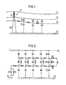
- the basic structure and the resulting capacitive couplings are shown schematically in FIG. 1.
- a single-phase high-voltage overhead line HF is drawn there, within the field area of which a metal-free, self-supporting optical cable OK is laid and held on the crossbar TR of a lattice tower GM.
- the earth rope is labeled ES and one of the phase ropes is labeled PS.
- the jacket surface can be simulated in the equivalent circuit diagram by a series of series resistances RL.
- Cross capacitances which are designated with CE, lie between the optical cable OK and the earth rope ES and the earth ED, while the replacement capacity between the optical cable OK and the phase rope PS is called CP.
- the equivalent circuit diagram shown also applies analogously to a multi-phase high-voltage line, with all phase conductors fusing to form a replacement phase conductor.
- the present invention which relates to a metal-free cable of the type mentioned, is based on the object of demonstrating a way in which the stress on the optical cables caused by leakage currents and arcing is avoided or reduced that can. According to the invention this is achieved in that the cable core is weakly electrically conductive, such that its resistivity is between 105 ⁇ cm and 1010 ⁇ cm.
- the dangerous resistance discontinuities on the surface of the optical cable are largely capacitively bridged and thus breakdowns and leakage currents are reduced or avoided to the extent that undesired material degradation or material destruction of the optical cable are also avoided.
- the equivalent circuit diagram according to FIG. 2 (see also the equivalent resistances and capacitances shown in FIG. 3) is obtained when both the cable sheath and the cable core are weakly electrically conductive in the sense of the invention.
- the transverse capacitances CP existing between the surface of the cable jacket of the optical cable OK and the phase conductor PS and the transverse capacitances CE existing between the cable and the earth ED yet another capacitance CM, which builds up between the surface of the cable sheath KM (formed in two layers in FIG. 3 and labeled MA1, MA2) and the cable core KS. It must be taken into account here that this jacket capacitance CM is over a hundred times larger than the partial capacitances CP and CE.
- the surface resistances ROL which are given by the degree of contamination and moistening of the outer jacket MA, are potential-controlled according to the invention by the internal longitudinal resistances RIL of the weakly conductive cable core KS.
- the size of the external longitudinal resistances ROL surface resistances
- This resistance RM lies between the surface of the cable jacket KM (symbolized by the series resistors ROL) and the cable core KS (symbolized by the series resistors RIL).
- r a is the outer radius and r i the inner radius of the jacket KM.
- CE is only in the order of about 5pF / m for custom made constructions
- ⁇ 1010 ⁇ ⁇ cm can only be achieved with a moisture-saturated FRNC ("fire resistant, non corrosive") mixture. In this respect, the conductivity of the jacket is of minor importance.
- the transverse resistance RM becomes smaller the thinner the jacket KM and the lower the specific insulation resistance of the jacket KM.
- the decisive factor is always the combined effect of capacitance and insulation resistance.
- the invention is based on the knowledge that the insulation capacity at least the cable core should be adapted to that of the surface, taking into account that the insulation value is reduced as a result of the contamination and moistening of the surface.
- the earth potential is carried by the mast even on a dry surface because the conductance of the cable core KS adapts only slowly to the changing air humidity. But this does not damage the jacket MA in its function.
- the cable core KS now only needs to be grounded together with the jacket. A current then flows continuously (of less than 1 mA) via the cable to earth, but this is an effect that can be easily controlled by earthing. Otherwise, a shock effect (but not a hazard) could occur if the KS cable core is touched under or behind the mast.
- High-strength plastic filaments with a ionogenic surface High-strength glass filaments with a ionogenic surface Mixtures of the two.
- Plastic or glass filaments provided with jonogene size, which are inherently insufficiently ionogenic.
- Plastic filaments can be made from polyamide, polyester, polycarbonate, etc., glass filaments from E or S glass.
- the resulting "insulation" resistances should be moisture-dependent (105 to 1010 ⁇ cm depending on moisture absorption) in order to achieve an automatic, but correspondingly delayed adaptation to climatic conditions. This ensures that, for example, an optical cable laid in a desert climate will not be damaged by partial discharges, because there is no moisture precipitation on the outside and no pollution (i.e. the ROL values according to Figure 2 remain high), and there is no increase in resistance inside (because there RIL values do not decrease due to the lack of moisture).
- the resulting cable series resistances ROL are then between 107 and 1012 ⁇ / m.
- Leakage-proof mixtures e.g. EVA, aluminum oxy hydrate powder filling
- polyolefins are not suitable as sheathing materials because their insulation resistance is very high and their DK ( ⁇ r) value is particularly small.
- the outer surface of the jacket must always be resistant to leakage currents in order to withstand residual charges, all moisture-absorbing materials (in the area of the cable core) are expediently provided with a moisture-dependent leakage current outer shell.
- aluminum hydroxide can be expediently mixed with the jacket material in the region of the outer shell, advantageously in the range between 10 and 60 percent by weight. Layers of polyamides or polyurethanes with such a jacket mixed with aluminum hydroxide are particularly reliable mechanically and electrically.
- the earthing area ie the area in which the cable is located, can become critical with the cable according to the invention eg in the area of the traverse (see also TR in Fig. 1) is lashed to earthed parts. Since here the entire earth current would flow off via the capacitance of the guy spiral AS, which is designated CS in FIG. 2, it is expedient to provide a bleeder resistor RS in this area which is as low-resistance as possible.
- earthing measures are particularly advantageous in the area of the core, ie the jacket is removed and earthing measures are provided in the area of the core, for example by means of appropriate conductive clamps, wire wrapping or the like.
- the same considerations also apply to the cable end, where it is also advisable to ground the mast.
- the expected currents are less than 1 mA, shock effects on people are completely excluded.
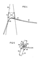
- Fig. 4 shows details of the grounding of the cable core (during assembly) in the area of the lattice tower GM.
- the jacket MA is removed in a section MX (see enlarged view in FIG. 5) and the exposed cable core KS is gripped with a coiled metal wire DW (or a clamp) and conductive with the bracing (guy spiral) AS and / or connected to the lattice tower GM.
- the settling point is then closed again with a sealing compound PM in order to maintain the longitudinal water tightness of the cable.
- the optical waveguides LW housed in the double-walled inner tube IT1, IT2 are normally embedded in a filling compound which results in longitudinal water tightness.
Landscapes
- Physics & Mathematics (AREA)
- General Physics & Mathematics (AREA)
- Optics & Photonics (AREA)
- Communication Cables (AREA)
- Insulated Conductors (AREA)
Abstract
Description
- Die Erfindung betrifft ein metallfreies, aus Kabelseele und Kabelmantel bestehendes selbsttragendes optisches Kabel für die Verwendung als Luftkabel im Feldbereich zwischen den Phasenseilen einer Hochspannungs-Freileitung.
- Optische Kabel werden vielfach im Bereich von Hochspannungs-Freileitungen verlegt, wobei zwei grundsätzlich unterschiedliche Anordnungen möglich sind. Bei der ersten Gestaltungsart sind die optischen Kabel in Phasen- oder Erdseile integriert oder an diesen angelascht. Bei der zweiten Ausführungsform werden die optischen Kabel als selbsttragende Strukturen aufgebaut und im Feldbereich, d.h. zwischen oder unter den Phasenseilen einer Hochspannungsleitung verlegt. Der grundsätzliche Aufbau und die sich dabei ergebenden kapazitiven Verkopplungen sind schematisch in Figur 1 dargestellt. Dort ist eine einphasige Hochspannungs-Freileitung HF gezeichnet, innerhalb deren Feldbeeich ein metallfreies selbsttragendes optisches Kabel OK verlegt und an der Traverse TR eines Gittermastes GM gehalten ist. Das Erdseil ist mit ES bezeichnet und eines der Phasenseile mit PS. Da das optische Kabel OK aus Isoliermaterial besteht, kann die Manteloberfläche im Ersatzschaltbild durch eine Folge von Längswiderständen RL nachgebildet werden. Zwischen dem optischen Kabel OK und dem Erdseil ES sowie der Erde ED liegen Querkapazitäten, die mit CE bezeichnet sind, während die Ersatzkapazität zwischen dem optischen Kabel OK und dem Phasenseil PS die Bezeichnung CP tragen.
- Das dargestellte Ersatzschaltbild gilt sinngemäß auch für eine mehrphasige Hochspannungsleitung, wobei sämtliche Phasenleiter zu einem Ersatz-Phasenleiter verschmelzen.
- Es hat sich gezeigt, daß die Mäntel sogenannter "volldielektrischer Kabel" vor allem in Höchstspannungsnetzen (d.h. solchen = ≧ 110 kV) infolge der am Kabelmantel auftretenden Spannungen Beschädigungen oder Zerstörungen durch Teilentladungsvorgänge ausgesetzt sein können. Ausgehend von dem Ersatzschaltbild nach Fig. 1 läßt sich hierfür folgende Erklärung geben: Die durch Feuchtigkeit und Ablagerungen (Verschmutzung mit dem Oberflächenwiderstand RL) behaftete Kabeloberfläche nimmt im Gleichgewicht - d.h. genügend weit von geerdeten Mastbauteilen entfernt - eine von den wirksamen Teilkapazitäten CE und CP bestimmte Spannung an. Diese kann im ungünstigsten Fall bis zu 50 % der Phasenspannung betragen. Der zugehörige Ladestrom fließt partiell über den Oberflächenwiderstand RL Richtung Mast ab. Dabei ist aber zu berücksichtigen, daß an Unterbrechungsstellen des Feuchtefilms oder der Verschmutzung infolge der entstehenden Widerstandserhöhungen (Widerstands-Unstetigkeit) Überschläge und Kriechströme in solcher Größenordnung entstehen können, daß dort das Material des Außenmantels des optischen Kabels OK abgebaut wird.Es sind also alle Übergangszustände zwischen feuchter und trockener Oberfläche oder zwischen mehr oder weniger verschmutzter Oberfläche besonders kritisch.
- Der vorliegenden Erfindung, welche sich auf ein metallfreies Kabel der eingangs genannten Art bezieht, liegt die Aufgabe zugrunde, einen Weg aufzuzeigen, wie die durch Kriechströme und Überschläge verursachte Beanspruchung der optischen Kabel vermieden oder verringert wer den kann. Gemäß der Erfindung wird dies dadurch erreicht, daß die Kabelseele schwach elektrisch leitend ausgebildet ist, derart, daß deren spezifischer Widerstand zwischen 10⁵ Ω cm und 10¹⁰ Ω cm liegt.
- Durch den Einbau der schwach leitenden Elemente im Bereich der Kabelseele werden die gefährlichen Widerstands-Unstetigkeiten ander Oberfläche der optischen Kabel weitgehend kapazitiv ohmisch überbrückt und damit Überschläge und Kriechströme soweit abgebaut oder vermieden, daß unerwünschter Materialabbau oder Materialzerstörung des optischen Kabels ebenfalls vermieden werden.
- Die Erfindung und ihre Weiterbildungen werden nachfolgend anhand von Zeichnungen näher erläutert. Es zeigen:
- Fig. 2 ein Ersatzschaltbild der erfindungsgemäßen Kabelkonstruktion,
- Fig. 3 ein Kabel nach der Erfindung in Querschnittsdarstellung,
- Fig. 4 die Abspannung am Mast und
- Fig. 5 die Erdung der Kabelseele.
- Das Ersatzschaltbild nach Fig. 2 (vgl.auch die in Fig. 3 eingezeichneten Ersatz-Widerstände und -Kapazitäten) wird dann erhalten, wenn sowohl der Kabelmantel als auch die Kabelseele im Sinne der Erfindung schwach elektrisch leitend ausgebildet sind. Neben den zwischen der Oberfläche des Kabelmantels des optischen Kabels OK und dem Phasenleiter PS bestehenden Querkapazitäten CP und den zwischen dem Kabel und der Erde ED bestehenden Querkapazitäten CE tritt noch eine weitere Kapazität CM auf, welche sich zwischen der Oberfläche des Kabelmantels KM (in Fig. 3 zweischichtig ausgebildet und mit MA1, MA2 bezeichnet) und der Kabelseele KS aufbaut. Dabei ist zu berücksichtigen, daß diese Mantelkapazität CM über hundertmal größer ist als die Teilkapazitäten CP und CE. Dies hat seine Ursache in dem gedrängten mechanischen Aufbau des optischen Kabels OK. Die Oberflächenwiderstände ROL, welche durch den Grad der Verschmutzung und Befeuchtung des Außenmantels MA gegeben sind, weden erfindungsgemäß durch die inneren Längswiderstände RIL der schwach leitenden Kabelseele KS potentialgesteuert. Die in ihrer Größe jeweils von dem äußeren Zustand des Kabelmantels KM abhängigen äußeren Längswiderstände ROL (Oberflächenwiderstände) werden zwar nicht völlig wirkungslos. Sie verlieren aber umsomehr an Wirkung, je größer die Mantelkapazität CM ist und je kleiner der zugehörige Ableitwiderstand RM. Dieser Widerstand RM liegt zwischen der Oberfläche des Kabelmantels KM (symbolisiert durch die Längswiderstände ROL) und der Kabelseele KS (symbolisiert durch die Längswiderstände RIL). Wie sich aus Fig. 3 ergibt, ist RM der Quer-Widerstand der Zylinderanordnung der Mantel-Außenoberfläche und der Mantel-Innenoberfläche. Somit gilt:
RM = ( 2 ·π· 1)⁻¹ . ρ . ln
Dabei ist ra der Außenradius und ri der Innenradius des Mantels KM. - Rechenbeispiel: Mantel KM innen: 10 mm 0̸
Mantel KM außen: 12 mm 0̸
Material-DK (εr): 3
spezifischer Widerstand: ρ = 10¹² Ω cm
- CE liegt für übliche Maßkonstruktionen nur in der Größenordnung von etwa 5pF/m

- Man sieht, daß der Mantel KM sehr niederohmig werden muß; um zum Gesamtquerleitwert nennenswert beizutragen. ρ = 10¹⁰ Ω· cm ist aber allenfalls von einer mit Feuchtigkeit gesättigten FRNC ("fire resistant, non corrosive")-Mischung zu erreichen. Insofern ist die Leitfähigkeit des Mantels von untergeordneter Bedeutung.
- Der Querwiderstand RM wird umso kleiner, je dünner der Mantel KM und je niedriger der spezifische Isolationswiderstand des Mantels KM ist. Der komplexe Querleitwert des Mantels KM ist G =+ j ·ω· CM. Entscheidend ist immer die gemeinsame Wirkung von Kapazität und Isolationswiderstand.

- Während die bisherige Auffassung bezüglich volldielektrischer Kabel im Bereich von Höchstspannungsleitungen dahin ging, möglichst hoch isolierende Kabelmaterialien für den Kabelmantel und die Kabelseele zu verwenden, geht die Erfindung von der Erkenntnis aus, daß das Isolationsvermögen zumindest der Kabelseele dem der Oberfläche angepaßt werden sollte, wobei eben zu berücksichtigen ist, daß infolge der Verschmutzung und Befeuchtung der Oberfläche es zu einer Erniedrigung von deren Isolationswert kommt. Auf diese Weise wird das Erdpotential zwar auch bei trockener Oberfläche vom Mast vorgetragen, weil der Leitwert der Kabelseele KS sich nur langsam der sich ändernden Luftfeuchte anpaßt. Doch entsteht daraus dem Mantel MA in seiner Funktion kein Schaden. Die Kabelseele KS muß jetzt nur zusammen mit dem Mantel geerdet werden. Es fließt dann ständig ein Strom (von unter 1 mA) über das Kabel zur Erde, doch ist dies ein in seiner Wirkung durch die Erdung leicht zu bekämpfender Effekt. Andernfalls könnte bei Berührung der Kabelseele KS auch unter oder hinter dem Mast Schockwirkung (aber keine Gefährdung) auftreten.
- Solange nur die Kabeloberfläche leitet, ist mit Abtrocknung derselben kein Effekt mehr vorhanden. Wenn nun die Kabelseele KS leitet, bleibt ein Erdstrom auch nach Abtrocknen der Manteloberfläche bestehen.
- Es ist also zweckmäßig, Seelen- und Mantelmaterialien zu verwenden, die einen mäßigen Isolations-Widerstand aufweisen. Dabei ist es besonders vorteilhaft, wenn dieser Widerstand zusätzlich durch eine Feuchteaufnahme erniedrigt wird. Diese Erniedrigung ist deswegen zwekcmäßig, weil am Anfang, (d.h. bei noch nicht verschmutztem Kabel) die Mantel-Längswiderstände ROL doch noch relativ hoch sind, wodurch ebenfalls relativ hohe Seelen-Längswiderstände RIL zulässig sind. Erst im Laufe der Verschmutzung werden die Mantel-Längswiderstände ROL niederohmiger, wobei gleichzeitig infolge von diffundierender Feuchtigkeitsanteilen durch den Kabelmantel auch im Inneren infolge der Feuchteaufnahme die Seelen-Längswiderstände RIL ebenfalls niederohmiger werden.
- Im Rahmen der Erfindung sind als dichtgepackte Seelenmaterialien insbesondere vorteilhaft:
Hochfeste Kunststoff-Filamente mit jonogener Oberfläche
Hochfeste Glas-Filamente mit jonogener Oberfläche
Mischungen aus beiden. - Mit jonogener Schlichte versehene Kunststoff- oder Glasfilamente, die von sich aus ungenügend jonogen sind.
- Mit Quellpulver oder jonogener Beschichtung angereicherte Filamente verschiedenster Art.
- Kunststoffilamente können aus Polyamid, Polyester, Polykarbonat usw. hersgestellt sein, Glasfilamente aus E- oder S-Glas.
- Bei all diesen Materialien sollen zweckmäßig die resultierenden "Isolations"-Widerstände feuchteabhängig (10⁵ bis 10¹⁰ Ω cm je nach Feuchteaufnahme) sein, um eine automatische, allerdings entsprechend verzügerte Anpassung an klimatische Bedingungen zu erreichen. Dadurch ist sichergestellt, daß z.B. ein in Wüstenklima verlegtes optisches Kabel keine Schäden durch Teilentladungen erfährt, weil hier außen keine Feuchtigkeitsniederschläge auftreten und keine Verschmutzung (also die ROL-Werte nach Figur 2 hoch bleiben) als auch im Inneren keine Widerstandserhöhung auftritt (weil dort die RIL-Werte durch die fehlende Feuchtigkeit nicht absinken). Die resultierenden Kabellängswiderstände ROL liegen dann zwischen 10⁷ und 10¹² Ω/m.
- Als Mantelmaterialien ROL sind besonders vorteilhaft:
- Für den Innenmantel (MA2):
Polyamide,
Polyurethane,
PVC (stark mit Kaolin/Kreide/Talkum gefüllt) - Für den Außenmantel:
Kriechstromfeste Mischungen
(z.B. EVA, Aluminium-Oxy-Hydrat-Pulver Füllung) - Alle diese Stoffe besitzen spezifische Isolationswiderstände < 10¹² Ω cm und DK (εr) - Werte > 3
- Nicht geeignet als Mantelmaterialien sind dagegen Polyolefine, weil ihr Isolationswiderstand sehr groß und ihr DK (ε r)-Wert besonders klein ist.
- Da aber die Mantelaußenfläche immer kriechstromresistent sein muß, um Restladungen zu ertragen, sind alle feuchteaufnehmenden Materialien (im Bereich der Kabelseele) zweckmäßig mit einer ebenfalls feuchteabhängigen Kriechstromaußenhülle zu versehen. In diesem Zusammenhang kann zweckmäßig im Bereich der Außenhülle Aluminium-Hydroxid dem Mantelmaterial zugemischt werden und zwar vorteilhaft im Bereich zwischen 10 und 60 Gewichtsprozent. Schichtungen aus Polyamiden oder Polyurethanen mit einem solchen mit Aluminium-Hydroxid versetzten Mantel sind mechanisch und elektrisch besonders zuverlässig.
- Kritisch kann bei dem erfindungsgemäßen Kabel der Erdungsbereich werden, d.h. derjenige Bereich, in dem das Kabel z.B. im Bereich der Traverse (vgl. auch TR in Fig. 1) an geerdeten Teilen angelascht wird. Da hier der gesamte Erdstrom über die in Fig. 2 mit CS bezichnete Kapazität der Abspannspirale AS abfließen würde, ist es zweckmäßig, in diesem Bereich einen Ableitwiderstand RS vorzusehen, der möglichst niederohmig ist. Um dies zu erreichen sind besonders Erdungsmaßnahmen auch im Bereich der Seele vorteilhaft, d.h. der Mantel wird abgesetzt und im Bereich der Seele werden Erdungsmaßnahmen vorgesehen, beispielsweise durch entsprechende leitende Schellen, Drahtbewicklungen o. dgl.. Die gleichen Überlegungen gelten auch für das Kabelende, wo ebenfalls zweckmäßig eine Erdung am Mast vorzunehmen ist. Obgleich die zu erwartenden Ströme kleiner l mA sind, werden damit Schockwirkungen auf Personen völlig ausgeschlossen.
- Fig. 4 zeigt Einzelheiten der Erdung der Kabelseele (während der Montage) im Bereich des Gittermastes GM. Beim optischen kabel OK wird in einem Teilabschnitt MX der Mantel MA abgesetzt (vgl. vergrößerte Darstellung in Fig. 5) und die freigelegte Kabelseele KS mit einem aufgewickelten Metalldraht DW (oder einer Schelle) gefaßt und leitend mit der Abspannung (Abspannspirale) AS und/oder dem Gittermast GM verbunden. Anschließend wird die Absetzstelle mit einer Dichtmasse PM wieder verschlossen, um die Längswasserdichtigkeit des Kabels zu erhalten. Dabei ist zu beachten, daß entgegen der vereinfachten Darstellung von Fig.3 die im doppelwandigen Innenrohr IT1, IT2 untergebrachten Lichtwellenleiter LW normalerweise in einer die Längswasserdichtigkeit ergebenden Füllmasse eingelagert sind.
- AS Abspannspirale
CE Querkapazität
CM Kapazität zwischen Kabelmantel und Kabelseele
CP Kapazität zwischen optischem Kabel und Phasenseil
CS Kapazität der Abspannspirale
DW Metalldraht
ED Erde
ES Erdseil
GM Gittermast
HF Hochspannungs-Freileitung
IT1, IT2 Innenrohr
KM Kabelmantel
KS Kabelseele
LW Lichtwellenleiter
MA1 Außenmantel
MA2 Innenmantel
MX Teilabschnitt
OK optisches Kabel
PM Dichtmasse
PS Phasenseil
RIL Längswiderstände der Kabelseele
RL Längswiderstand
RM Ableitwiderstand
ROL Oberflächenwiderstand des Kabelmantels
RS Ableitwiderstand
TR Traverse
Claims (12)
Priority Applications (1)
| Application Number | Priority Date | Filing Date | Title |
|---|---|---|---|
| AT86111000T ATE73937T1 (de) | 1985-08-12 | 1986-08-08 | Metallfreies selbsttragendes optisches kabel fuer hochspannungsfreileitungen. |
Applications Claiming Priority (2)
| Application Number | Priority Date | Filing Date | Title |
|---|---|---|---|
| DE3528927 | 1985-08-12 | ||
| DE3528927 | 1985-08-12 |
Publications (3)
| Publication Number | Publication Date |
|---|---|
| EP0214480A2 true EP0214480A2 (de) | 1987-03-18 |
| EP0214480A3 EP0214480A3 (en) | 1989-05-31 |
| EP0214480B1 EP0214480B1 (de) | 1992-03-18 |
Family
ID=6278336
Family Applications (1)
| Application Number | Title | Priority Date | Filing Date |
|---|---|---|---|
| EP86111000A Expired - Lifetime EP0214480B1 (de) | 1985-08-12 | 1986-08-08 | Metallfreies selbsttragendes optisches Kabel für Hochspannungsfreileitungen |
Country Status (4)
| Country | Link |
|---|---|
| US (1) | US4776665A (de) |
| EP (1) | EP0214480B1 (de) |
| AT (1) | ATE73937T1 (de) |
| DE (1) | DE3684388D1 (de) |
Cited By (9)
| Publication number | Priority date | Publication date | Assignee | Title |
|---|---|---|---|---|
| EP0315824A1 (de) * | 1987-10-28 | 1989-05-17 | Siemens Aktiengesellschaft | Metallfreies selbsttragendes optisches Kabel |
| EP0403285A3 (de) * | 1989-06-14 | 1991-07-31 | BICC Public Limited Company | Optisches Luftkabelübertragungssystem |
| WO1991016648A1 (en) * | 1990-04-26 | 1991-10-31 | Nkf Kabel B.V. | Cladding structure, in particular for optical cables, for use in high-voltage environments |
| WO1993005424A1 (en) * | 1991-09-10 | 1993-03-18 | Neste Oy | Optical cable |
| WO1995016933A1 (en) * | 1993-12-17 | 1995-06-22 | Bicc Public Limited Company | Semiconductive linear element |
| EP0709700A1 (de) * | 1994-10-28 | 1996-05-01 | BICC Public Limited Company | System zur gemeinsamen Übertragung von elektrischer und optischer Energie |
| WO1997006459A1 (en) * | 1995-08-05 | 1997-02-20 | Bicc Public Limited Company | Method of installing a resistive element on an optical cable |
| US6519396B2 (en) | 2000-06-09 | 2003-02-11 | Ccs Technology, Inc. | Aerial cable containing optical transmission elements and process for the manufacture of an aerial cable |
| WO2008000371A1 (en) * | 2006-06-28 | 2008-01-03 | Teijin Aramid B.V. | Antitracking aramid yarn |
Families Citing this family (11)
| Publication number | Priority date | Publication date | Assignee | Title |
|---|---|---|---|---|
| US4832442A (en) * | 1987-07-17 | 1989-05-23 | United Ropeworks (U.S.A.) Inc. | Method and apparatus for aerial installation of fiber optic cables |
| US5230034A (en) * | 1991-09-20 | 1993-07-20 | Bottoms Jack Jr | All dielectric self-supporting fiber optic cable |
| US5325457A (en) * | 1991-09-20 | 1994-06-28 | Bottoms Jack Jr | Field protected self-supporting fiber optic cable |
| GB9210063D0 (en) * | 1992-05-09 | 1992-06-24 | Bicc Plc | Overhead optical transmission system |
| US5331606A (en) * | 1992-05-29 | 1994-07-19 | Western Atlas International, Inc. | Static dissipating data cable and seismic apparatus |
| GB9308361D0 (en) * | 1993-04-22 | 1993-06-09 | Bicc Plc | Optical cable |
| US5621843A (en) * | 1994-06-09 | 1997-04-15 | Ceramoptec Industries, Inc. | Silica lightguide for UV applications |
| US6191354B1 (en) * | 1998-04-16 | 2001-02-20 | Professional Communications, S. A. | Transmission conduit and method of installation |
| US6356690B1 (en) | 1999-10-20 | 2002-03-12 | Corning Cable Systems Llc | Self-supporting fiber optic cable |
| DE10032247A1 (de) * | 2000-07-03 | 2002-01-17 | Scc Special Comm Cables Gmbh | Metallfreies, selbsttragendes optisches Kabel und Verfahren zur Montage des optischen Kabels |
| DE102005039482A1 (de) * | 2005-08-18 | 2007-02-22 | CCS Technology, Inc., Wilmington | Optisches Übertragungselement und Verfahren zum Herstellen eines optischen Übertragungselements |
Family Cites Families (9)
| Publication number | Priority date | Publication date | Assignee | Title |
|---|---|---|---|---|
| US3935042A (en) * | 1974-07-08 | 1976-01-27 | General Electric Company | Method of manufacturing corona-resistant ethylene-propylene rubber insulated power cable, and the product thereof |
| US4342500A (en) * | 1979-08-10 | 1982-08-03 | Siemens Aktiengesellschaft | High voltage stabile optical cable structures |
| DE3023669C2 (de) * | 1980-06-25 | 1983-01-20 | Philips Kommunikations Industrie AG, 8500 Nürnberg | Selbsttragendes optisches Nachrichtenkabel |
| DE3118172A1 (de) * | 1981-05-08 | 1982-11-25 | Philips Kommunikations Industrie AG, 8500 Nürnberg | Laengswasserdichtes optisches nachrichtenkabel |
| US4358637A (en) * | 1981-06-17 | 1982-11-09 | Societa Cavi Pirelli S.P.A. | Above-ground conductor unit with corona noise reducing covering comprising a conductive material and a hydrophilic material |
| WO1984000216A1 (fr) * | 1982-07-05 | 1984-01-19 | Furukawa Electric Co Ltd | Fibre optique enduite |
| AU568618B2 (en) * | 1982-12-13 | 1988-01-07 | Afl Telecommunications Europe Limited | Fibre optic cable arrangement |
| JPS5995304U (ja) * | 1982-12-18 | 1984-06-28 | 東北電力株式会社 | ノンメタリツク自己支持型架空光ケ−ブル |
| DE3375619D1 (en) * | 1983-06-13 | 1988-03-10 | Mitsui Du Pont Polychemical | Semiconducting compositions and wires and cables using the same |
-
1986
- 1986-07-18 US US06/886,830 patent/US4776665A/en not_active Expired - Lifetime
- 1986-08-08 DE DE8686111000T patent/DE3684388D1/de not_active Expired - Lifetime
- 1986-08-08 EP EP86111000A patent/EP0214480B1/de not_active Expired - Lifetime
- 1986-08-08 AT AT86111000T patent/ATE73937T1/de not_active IP Right Cessation
Cited By (14)
| Publication number | Priority date | Publication date | Assignee | Title |
|---|---|---|---|---|
| EP0315824A1 (de) * | 1987-10-28 | 1989-05-17 | Siemens Aktiengesellschaft | Metallfreies selbsttragendes optisches Kabel |
| EP0403285A3 (de) * | 1989-06-14 | 1991-07-31 | BICC Public Limited Company | Optisches Luftkabelübertragungssystem |
| WO1991016648A1 (en) * | 1990-04-26 | 1991-10-31 | Nkf Kabel B.V. | Cladding structure, in particular for optical cables, for use in high-voltage environments |
| US5317665A (en) * | 1990-04-26 | 1994-05-31 | Nkf Kabel B.V. | Jacket structure for optical cables, for use in high-voltage environments |
| WO1993005424A1 (en) * | 1991-09-10 | 1993-03-18 | Neste Oy | Optical cable |
| EP0660149A1 (de) * | 1993-12-17 | 1995-06-28 | BICC Public Limited Company | Linear halbleitendes Element |
| WO1995016933A1 (en) * | 1993-12-17 | 1995-06-22 | Bicc Public Limited Company | Semiconductive linear element |
| US5563976A (en) * | 1993-12-17 | 1996-10-08 | Bicc Public Limited Company | Semiconductive linear element including partially pyrolised polyacrylonitrile |
| EP0709700A1 (de) * | 1994-10-28 | 1996-05-01 | BICC Public Limited Company | System zur gemeinsamen Übertragung von elektrischer und optischer Energie |
| WO1996013740A1 (en) * | 1994-10-28 | 1996-05-09 | Bicc Public Limited Company | Combined electrical power and optical transmission system |
| US5526457A (en) * | 1994-10-28 | 1996-06-11 | Bicc Public Limited Company | Method and apparatus for preventing dry band arcing in a combined overhead electrical power and optical transmission system |
| WO1997006459A1 (en) * | 1995-08-05 | 1997-02-20 | Bicc Public Limited Company | Method of installing a resistive element on an optical cable |
| US6519396B2 (en) | 2000-06-09 | 2003-02-11 | Ccs Technology, Inc. | Aerial cable containing optical transmission elements and process for the manufacture of an aerial cable |
| WO2008000371A1 (en) * | 2006-06-28 | 2008-01-03 | Teijin Aramid B.V. | Antitracking aramid yarn |
Also Published As
| Publication number | Publication date |
|---|---|
| EP0214480A3 (en) | 1989-05-31 |
| ATE73937T1 (de) | 1992-04-15 |
| US4776665A (en) | 1988-10-11 |
| EP0214480B1 (de) | 1992-03-18 |
| DE3684388D1 (de) | 1992-04-23 |
Similar Documents
| Publication | Publication Date | Title |
|---|---|---|
| EP0214480B1 (de) | Metallfreies selbsttragendes optisches Kabel für Hochspannungsfreileitungen | |
| DE69811513T2 (de) | Trockener elektrischer kabelendverschluss | |
| DE69607112T2 (de) | Verbindung von energiekabeln | |
| EP0416452A2 (de) | Elektrofilterkabel | |
| DE102008009333A1 (de) | Feldgesteuerter Verbundisolator | |
| EP1009083A2 (de) | Kabelgarnitur zum Schutz einer Kabelverbindung in der Mittelspannungstechnik | |
| DE1640278A1 (de) | Kabelendabschluss | |
| DE10228665B4 (de) | Biltzstromableiteinrichtung | |
| EP0519228A1 (de) | Hochspannungskapselung mit mindestens zwei Schutzbelägen | |
| DE10233528A1 (de) | Blitzstromableiteinrichtung | |
| DE3103209A1 (de) | Hochspannungs-zuendkabel | |
| DE3103210C2 (de) | Hochspannungs-Zündkabel | |
| DE3736333A1 (de) | Starkstromkabel mit feuchtesensor | |
| DE2737108A1 (de) | Elektrisches kabel mit feuchtigkeitssperre | |
| DE2601545B2 (de) | Verbindungsmuffe für den Übergang von Papiermassekabeln auf kunststoffisolierte Kabel | |
| DE1640699A1 (de) | Endenabschluss fuer Hochspannungskabel und -leitungen | |
| DE1235419B (de) | Transformator-Durchfuehrung von Leistungstransformatoren fuer sehr hohe Betriebsspannungen von ueber 300 kV | |
| CH652524A5 (de) | Feuchtigkeitsgeschuetztes elektrisches kabel. | |
| DE102018201160A1 (de) | Hochspannungsdurchführung, elektrisches Gerät mit Hochspannungsdurchführung und Verfahren zur Herstellung des elektrischen Gerätes | |
| CH645483A5 (de) | Vorrichtung zur ueberspannungsableitung. | |
| DE3100221C2 (de) | Übergangsmuffe zur Verbindung von ölgetränkten, papierisolierten Kabeln mit kunststoffisolierten Kabeln | |
| DE1557162C3 (de) | Vorrichtung zur korrosionsbeständigen Erdung von Niederschlagselektrodenröhren | |
| DE3443192A1 (de) | Mit einer schutzhuelle abgeschlossenes kunststoffisoliertes mittelspannungskabel mit resistiver steuerschicht | |
| DE1515427A1 (de) | Elektrisches Kabel | |
| DE2555653C2 (de) | Endverschlußgarnitur für kunststoffisolierte Mehrleiter-Starkstromkabel mit unterschiedlichen Feldbegrenzungen |
Legal Events
| Date | Code | Title | Description |
|---|---|---|---|
| PUAI | Public reference made under article 153(3) epc to a published international application that has entered the european phase |
Free format text: ORIGINAL CODE: 0009012 |
|
| AK | Designated contracting states |
Kind code of ref document: A2 Designated state(s): AT BE CH DE FR GB IT LI NL SE |
|
| PUAL | Search report despatched |
Free format text: ORIGINAL CODE: 0009013 |
|
| AK | Designated contracting states |
Kind code of ref document: A3 Designated state(s): AT BE CH DE FR GB IT LI NL SE |
|
| 17P | Request for examination filed |
Effective date: 19890627 |
|
| 17Q | First examination report despatched |
Effective date: 19910729 |
|
| GRAA | (expected) grant |
Free format text: ORIGINAL CODE: 0009210 |
|
| AK | Designated contracting states |
Kind code of ref document: B1 Designated state(s): AT BE CH DE FR GB IT LI NL SE |
|
| REF | Corresponds to: |
Ref document number: 73937 Country of ref document: AT Date of ref document: 19920415 Kind code of ref document: T |
|
| REF | Corresponds to: |
Ref document number: 3684388 Country of ref document: DE Date of ref document: 19920423 |
|
| ET | Fr: translation filed | ||
| ITF | It: translation for a ep patent filed | ||
| GBT | Gb: translation of ep patent filed (gb section 77(6)(a)/1977) | ||
| PLBI | Opposition filed |
Free format text: ORIGINAL CODE: 0009260 |
|
| 26 | Opposition filed |
Opponent name: KABELMETAL ELECTRO GMBH Effective date: 19921216 |
|
| NLR1 | Nl: opposition has been filed with the epo |
Opponent name: KABELMETAL ELECTRO GMBH |
|
| EAL | Se: european patent in force in sweden |
Ref document number: 86111000.5 |
|
| APAC | Appeal dossier modified |
Free format text: ORIGINAL CODE: EPIDOS NOAPO |
|
| PLBN | Opposition rejected |
Free format text: ORIGINAL CODE: 0009273 |
|
| STAA | Information on the status of an ep patent application or granted ep patent |
Free format text: STATUS: OPPOSITION REJECTED |
|
| 27O | Opposition rejected |
Effective date: 19930801 |
|
| NLR2 | Nl: decision of opposition | ||
| PGFP | Annual fee paid to national office [announced via postgrant information from national office to epo] |
Ref country code: SE Payment date: 20010719 Year of fee payment: 16 |
|
| PGFP | Annual fee paid to national office [announced via postgrant information from national office to epo] |
Ref country code: GB Payment date: 20010720 Year of fee payment: 16 Ref country code: CH Payment date: 20010720 Year of fee payment: 16 Ref country code: AT Payment date: 20010720 Year of fee payment: 16 |
|
| PGFP | Annual fee paid to national office [announced via postgrant information from national office to epo] |
Ref country code: BE Payment date: 20010810 Year of fee payment: 16 |
|
| REG | Reference to a national code |
Ref country code: GB Ref legal event code: IF02 |
|
| PGFP | Annual fee paid to national office [announced via postgrant information from national office to epo] |
Ref country code: NL Payment date: 20020722 Year of fee payment: 17 |
|
| PG25 | Lapsed in a contracting state [announced via postgrant information from national office to epo] |
Ref country code: GB Free format text: LAPSE BECAUSE OF NON-PAYMENT OF DUE FEES Effective date: 20020808 Ref country code: AT Free format text: LAPSE BECAUSE OF NON-PAYMENT OF DUE FEES Effective date: 20020808 |
|
| PG25 | Lapsed in a contracting state [announced via postgrant information from national office to epo] |
Ref country code: SE Free format text: LAPSE BECAUSE OF NON-PAYMENT OF DUE FEES Effective date: 20020809 |
|
| PG25 | Lapsed in a contracting state [announced via postgrant information from national office to epo] |
Ref country code: LI Free format text: LAPSE BECAUSE OF NON-PAYMENT OF DUE FEES Effective date: 20020831 Ref country code: CH Free format text: LAPSE BECAUSE OF NON-PAYMENT OF DUE FEES Effective date: 20020831 Ref country code: BE Free format text: LAPSE BECAUSE OF NON-PAYMENT OF DUE FEES Effective date: 20020831 |
|
| BERE | Be: lapsed |
Owner name: *SIEMENS A.G. Effective date: 20020831 |
|
| EUG | Se: european patent has lapsed | ||
| GBPC | Gb: european patent ceased through non-payment of renewal fee |
Effective date: 20020808 |
|
| REG | Reference to a national code |
Ref country code: CH Ref legal event code: PL |
|
| PG25 | Lapsed in a contracting state [announced via postgrant information from national office to epo] |
Ref country code: NL Free format text: LAPSE BECAUSE OF NON-PAYMENT OF DUE FEES Effective date: 20040301 |
|
| NLV4 | Nl: lapsed or anulled due to non-payment of the annual fee |
Effective date: 20040301 |
|
| REG | Reference to a national code |
Ref country code: FR Ref legal event code: TP |
|
| PG25 | Lapsed in a contracting state [announced via postgrant information from national office to epo] |
Ref country code: IT Free format text: LAPSE BECAUSE OF NON-PAYMENT OF DUE FEES Effective date: 20050808 |
|
| PGFP | Annual fee paid to national office [announced via postgrant information from national office to epo] |
Ref country code: FR Payment date: 20050817 Year of fee payment: 20 |
|
| PGFP | Annual fee paid to national office [announced via postgrant information from national office to epo] |
Ref country code: DE Payment date: 20050930 Year of fee payment: 20 |
|
| APAH | Appeal reference modified |
Free format text: ORIGINAL CODE: EPIDOSCREFNO |