US4778374A - Apparatus for forming tampon inserter tip - Google Patents
Apparatus for forming tampon inserter tip Download PDFInfo
- Publication number
- US4778374A US4778374A US07/126,727 US12672787A US4778374A US 4778374 A US4778374 A US 4778374A US 12672787 A US12672787 A US 12672787A US 4778374 A US4778374 A US 4778374A
- Authority
- US
- United States
- Prior art keywords
- gripper
- tip
- tampon inserter
- cam
- tampon
- Prior art date
- Legal status (The legal status is an assumption and is not a legal conclusion. Google has not performed a legal analysis and makes no representation as to the accuracy of the status listed.)
- Expired - Fee Related
Links
Images


Classifications
-
- A—HUMAN NECESSITIES
- A61—MEDICAL OR VETERINARY SCIENCE; HYGIENE
- A61F—FILTERS IMPLANTABLE INTO BLOOD VESSELS; PROSTHESES; DEVICES PROVIDING PATENCY TO, OR PREVENTING COLLAPSING OF, TUBULAR STRUCTURES OF THE BODY, e.g. STENTS; ORTHOPAEDIC, NURSING OR CONTRACEPTIVE DEVICES; FOMENTATION; TREATMENT OR PROTECTION OF EYES OR EARS; BANDAGES, DRESSINGS OR ABSORBENT PADS; FIRST-AID KITS
- A61F13/00—Bandages or dressings; Absorbent pads
- A61F13/15—Absorbent pads, e.g. sanitary towels, swabs or tampons for external or internal application to the body; Supporting or fastening means therefor; Tampon applicators
- A61F13/20—Tampons, e.g. catamenial tampons; Accessories therefor
- A61F13/2082—Apparatus or processes of manufacturing
- A61F13/2085—Catamenial tampons
-
- B—PERFORMING OPERATIONS; TRANSPORTING
- B29—WORKING OF PLASTICS; WORKING OF SUBSTANCES IN A PLASTIC STATE IN GENERAL
- B29C—SHAPING OR JOINING OF PLASTICS; SHAPING OF MATERIAL IN A PLASTIC STATE, NOT OTHERWISE PROVIDED FOR; AFTER-TREATMENT OF THE SHAPED PRODUCTS, e.g. REPAIRING
- B29C31/00—Handling, e.g. feeding of the material to be shaped, storage of plastics material before moulding; Automation, i.e. automated handling lines in plastics processing plants, e.g. using manipulators or robots
- B29C31/002—Handling tubes, e.g. transferring between shaping stations, loading on mandrels
-
- B—PERFORMING OPERATIONS; TRANSPORTING
- B29—WORKING OF PLASTICS; WORKING OF SUBSTANCES IN A PLASTIC STATE IN GENERAL
- B29C—SHAPING OR JOINING OF PLASTICS; SHAPING OF MATERIAL IN A PLASTIC STATE, NOT OTHERWISE PROVIDED FOR; AFTER-TREATMENT OF THE SHAPED PRODUCTS, e.g. REPAIRING
- B29C51/00—Shaping by thermoforming, i.e. shaping sheets or sheet like preforms after heating, e.g. shaping sheets in matched moulds or by deep-drawing; Apparatus therefor
- B29C51/18—Thermoforming apparatus
-
- B—PERFORMING OPERATIONS; TRANSPORTING
- B29—WORKING OF PLASTICS; WORKING OF SUBSTANCES IN A PLASTIC STATE IN GENERAL
- B29C—SHAPING OR JOINING OF PLASTICS; SHAPING OF MATERIAL IN A PLASTIC STATE, NOT OTHERWISE PROVIDED FOR; AFTER-TREATMENT OF THE SHAPED PRODUCTS, e.g. REPAIRING
- B29C57/00—Shaping of tube ends, e.g. flanging, belling or closing; Apparatus therefor, e.g. collapsible mandrels
- B29C57/10—Closing
Definitions
- This invention relates to an apparatus for forming the petal-like segments at the tip of the outer cylinder of a double-cylinder sanitary tampon inserter of synthetic resin into a hemispherically curved shape.
- a double-cylinder sanitary tampon inserter of the type disclosed, for example, in U.S. Pat Nos. 4,291,696 and 4,276,881 comprises an inner cylinder doubling as a tampon holder and a push rod and an outer cylinder to hold the inner cylinder.
- the claws provided on the outer cylinder are allowed to project into the inner cylinder through the grooves cut in the inner cylinder so that the claws keep a tampon inside the outer cylinder when the inner cylinder is withdrawn.
- This type of tampon inserter has the advantage of greater compactness and portability over other types of conventional tampon inserters.
- the tip of the outer cylinder is formed into hemispherically curved petal-like segments. Because of the limitations involved in the shape of molds and the number of shots in injection molding, it is advantageous to form straight petal-like segments first and then curve such straight segments into the desired hemispherical shape in a subsequent process, rather than forming curved segments in the beginning.
- This type of molding method is already known, as is proposed in U.S. Pat. No. 3,895,634, Japanese Provisional Patent Publication Nos. 55-166149 and 58-36553.
- JP A No. 58-36553 which has advantages for industrial use divides the tip of the outer cylinder into straight petal-like segments which are first put into a heating mold having a hemispherically curved recess and then, after being heated and softened, into a cooling mold having a similar hemispherically curved recess for hardening.
- An object of this invention is to provide a practical apparatus for continuously and rapidly accomplishing the aforementioned operation to form the petal-like segments at the tip of a tampon inserter into a hemispherically curved shape.
- Another object of this invention is to provide an apparatus for fully automatically and efficiently forming the petal-like segments at the tip of a tampon inserter into a hemispherically curved shape.
- a tampon inserter tip forming apparatus has a rotary table that is turned about a shaft by a drive unit, with sets of molds, each of which comprises a heating mold in which the tip of the tampon inserter is heated and softened and a cooling mold in which the heated and softened tip is shaped while being cooled, disposed around the periphery of the rotary table.
- a cam mechanism is provided on the shaft so that either of the heating and cooling molds is positioned, at one or the other end of a guide, above a tampon inserter held by a gripper.
- One tampon inserter gripper is provided for each mold unit on the rotary table.
- the tampon inserter gripper comprises a pair of gripper segments that are opened and closed by another cam mechanism and raised and lowered by still another cam mechanism provided on the shaft.
- the cam mechanisms are so arranged that the gripper releases the tampon inserter which has been put first in the heating mold and then in the cooling mold.
- each of the cam mechanisms interlockingly moves the heating and cooling molds, opens and closes the gripper, and raises and lowers the gripper. Accordingly, the tip of a tampon inserter held by the gripper first enters the heating mold. While the heated tip is lowered temporarily, the cooling mold is moved to above the tampon inserter. When the tampon inserter is raised again, the heated tip comes in contact with the inner surface of the cooling mold to become hemispherically shaped while being cooled.
- this invention provides a practical automatic forming apparatus that continuously and rapidly forms the petal-like segments at the tip of a tampon inserter into a hemispherically curved shape.
- FIG. 1 is a general cross-sectional view of a forming apparatus according to this invention.
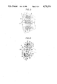
- FIGS. 2 and 3 are a vertical cross-sectional view and a bottom view showing the principal parts of molds carried by a rotary table and other mechanisms associated therewith.
- FIGS. 4 and 5 are a vertical cross-sectional view and a bottom view showing the principal parts of a mechanism to hold and transfer a tampon inserter.
- FIGS. 1 to 5 illustrate an apparatus for forming the tip of a tampon inserter embodying the principle of this invention.
- a shaft 2 to support the whole apparatus is erected at the center of a base 1, with a rotary table 3 rotatably mounted on the shaft 2.
- a drive unit, not shown, turns the rotary table 3 through a drive wheel 4. While the rotary table 3 is thus turned around the shaft 2 once, the tip of a tampon inserter is formed as elaborated below.
- the rotary table 3 carries two support tables 5 and 6, the former placed above the latter. While the upper support table 5 carries a set of molds 7 and 8 for forming the tip of a tampon inserter A, the lower support table 6 carries a mechanism to hold and transfer the tampon inserter A to where the molds 7 and 8 are positioned.
- Each pair of the molds 7 and 8 carried by the upper support table 5 consists of a heating mold 7 for heating and softening the tip of the tampon inserter A and a cooling mold 8 for cooling the heated and softened tip, as shown in FIGS. 1 to 3.
- the paired heating and cooling molds 7 and 8 are attached to a slider 10 with a given space left therebetween.
- the slider 10 is slidably supported between a pair of guides 11 attached to the support table 5. With the slider 10 supported by the guides 11 as illustrated, the cavities 12 and 13 provided in the heating and cooling molds 7 and 8 open downward.
- Pairs of the guides 11 are radially attached to the support table 5 around the shaft 2, with each pair of the guides 11 supporting the slider 10 to which the molds 7 and 8 are attached.
- the heating mold 7 has a band heater 14 wound therearound and a temperature sensor 15 mounted therein, the heater 14 and the sensor 15 being connected to a controller, not shown, so that the temperature in the cavity 12 is kept substantially constant.
- the cooling mold 8 has an inner passage 16 through which cooling water is passed.
- the water passage 16 communicates with water supplying and draining passages 19 in the shaft 2 through a flexible tube 17 and a manifold 18. Water supplied and drained through the passages 19 cools the inside of the cavity 13.
- the slider 10 slidably supported by the guides 11 has a cam follower 22 projecting upward through a slot in the support table 5.
- the cam follower 22 is adapted to move along a ring-shaped cam 21 attached to a support frame 20 fastened to the shaft 2. While the cam follower 22 consists of a roller rotatably supported by the slider 10, the ring-shaped cam 21 consists of an annular plate cut with a cam groove 21 and mounted around the shaft 2.
- the cam groove 23 allows the slider 10 to slide to one end of the guides 11, thereby bringing the heating mold 7 into the position above the tampon inserter A.
- the cam groove 23 allows the slider 10 to slide to the other end of the guides 11, thereby bringing the cooling mold 8 into the position above the tampon inserter A.
- the mechanism for holding and transferring the tampon inserter A consists of a gripper 25 that grips and brings a successively fed tampon inserter A into the desired position below the molds 7 and 8. As many grippers 25 as the pairs of the molds 7 and 8 are mounted on the support table 6.
- the gripper 25 comprises sleeves 28 and 29 that are fitted over a pair of gripper shafts 26 and 27 in such a manner as not to rotate but to slide with respect to each other by means of spline or other engaging means, as elaborated in FIGS. 4 and 5.
- the sleeves 28 and 29 are slidably passed through the support table 6, with a pair of gripper segments 30 and 31 to pinch the tampon inserter A attached to the tip of the sleeves 28 and 29.
- Mating spur gears 32 and 33 are attached to the lower portion of the gripper shafts 26 and 27.
- a lever 34 is attached to the lower end of the gripper shaft 26.
- a cam follower 35 rotatably attached to the tip of the lever 34 is kept in contact with a sector cam 36 that is fastened to the shaft 2 to open and close the gripper.
- a spring 39 to urge the gripper segments 30 and 31 in the closing direction is provided between projections 37 and 38 protruding from the gripper shafts 26 and 27.
- a support 41 is fitted over each of the sleeves 28 and 29 in such a manner that the sleeves 28 and 29 are rotatable therein but are allowed to move integrally therewith in the axial direction.
- the support 41 rotatably supports a cam follower 42 that is kept in contact with a lifting cam 43 fastened to the shaft 2.
- the lifting cam raises and lowers the gripper 25 by means of the surface irregularities on the cam face contacting the cam follower 42, thereby moving the tampon inserter A into and away from the cavities 12 and 13 in the molds 7 and 8.
- the drive unit turns the rotary table 3 in the tampon inserter tip forming apparatus described above
- the sector cam 36 opening and closing the gripper 25 and the lifting cam 43 raising and lowering the gripper 25 move the cam followers 22, 35 and 42, respectively, to accomplish the forming of the tip of the tampon inserter A.
- the lifting cam 43 raises the gripper 25 holding the tampon inserter A until the tip thereof enters the heating mold 7 where heating is done.
- the lifting cam 43 temporarily lowers the gripper 25.
- the cam 21 moves the cooling mold 8 to above the tampon inserter A.
- the lifting cam 43 raises the tampon inserter A again, the heated tip thereof comes in contact with the inner surface of the cooling mold 8 and gets thereby formed into a hemispherically curved shape while being cooled.
- the lifting cam 43 lowers the gripper 25, which, in turn, releases the tampon inserter A when the sector cam 36 presses the cam follower 35 and gets ready for the acceptance of the next tampon inserter A.
- the upper support table 5 carries the set of forming molds 7 and 8 while the lower support table 6 carries the means to hold and transfer a tampon inserter A. But a reversed arrangement is possible, as well.
Landscapes
- Engineering & Computer Science (AREA)
- Health & Medical Sciences (AREA)
- Mechanical Engineering (AREA)
- Life Sciences & Earth Sciences (AREA)
- General Health & Medical Sciences (AREA)
- Biomedical Technology (AREA)
- Heart & Thoracic Surgery (AREA)
- Vascular Medicine (AREA)
- Manufacturing & Machinery (AREA)
- Animal Behavior & Ethology (AREA)
- Epidemiology (AREA)
- Public Health (AREA)
- Veterinary Medicine (AREA)
- Robotics (AREA)
- Absorbent Articles And Supports Therefor (AREA)
- Blow-Moulding Or Thermoforming Of Plastics Or The Like (AREA)
- Shaping Of Tube Ends By Bending Or Straightening (AREA)
Applications Claiming Priority (1)
| Application Number | Priority Date | Filing Date | Title |
|---|---|---|---|
| JP61218792A JPH0717004B2 (ja) | 1986-09-17 | 1986-09-17 | タンポン挿入具先端部の成形装置 |
Publications (1)
| Publication Number | Publication Date |
|---|---|
| US4778374A true US4778374A (en) | 1988-10-18 |
Family
ID=16725437
Family Applications (1)
| Application Number | Title | Priority Date | Filing Date |
|---|---|---|---|
| US07/126,727 Expired - Fee Related US4778374A (en) | 1986-09-17 | 1987-11-30 | Apparatus for forming tampon inserter tip |
Country Status (3)
| Country | Link |
|---|---|
| US (1) | US4778374A (fr) |
| EP (1) | EP0260932A3 (fr) |
| JP (1) | JPH0717004B2 (fr) |
Cited By (6)
| Publication number | Priority date | Publication date | Assignee | Title |
|---|---|---|---|---|
| US5501063A (en) * | 1994-09-06 | 1996-03-26 | Kimberly-Clark Corporation | Apparatus and method of reducing the force to expel a tampon from a tampon applicator and the applicator itself |
| US5571540A (en) * | 1994-09-06 | 1996-11-05 | Kimberly-Clark Corporation | Apparatus for crimping, pleating and forming a tip on a hollow tube |
| US5614230A (en) * | 1994-12-29 | 1997-03-25 | Kimberly-Clark Corporation | Apparatus for forming a curl on an end of a tubular member |
| WO2004002692A1 (fr) * | 2002-06-26 | 2004-01-08 | Playtex Products, Inc. | Appareil et procede de fabrication d'un applicateur de tampon |
| US20090218729A1 (en) * | 2008-02-29 | 2009-09-03 | Pelley Kenneth A | Method and apparatus to form a spherical end of an elongated cylindrical tube |
| WO2021058765A1 (fr) * | 2019-09-27 | 2021-04-01 | Johnson & Johnson Gmbh | Appareil pour former un tampon cataménial |
Families Citing this family (1)
| Publication number | Priority date | Publication date | Assignee | Title |
|---|---|---|---|---|
| US8282614B2 (en) * | 2006-11-20 | 2012-10-09 | The Procter And Gamble Company | Method and apparatus for producing stabilized absorbent structure |
Citations (10)
| Publication number | Priority date | Publication date | Assignee | Title |
|---|---|---|---|---|
| US647993A (en) * | 1899-08-29 | 1900-04-24 | Johann Schmidt | Process of making capsules. |
| US3433225A (en) * | 1965-12-22 | 1969-03-18 | Joseph A Voss | Hygienic devices and methods of making the same |
| US3581744A (en) * | 1968-05-03 | 1971-06-01 | Joseph A Voss | Laminated tube structure |
| US3694859A (en) * | 1970-11-23 | 1972-10-03 | Glassman Jacob A | Apparatus for forming catamenial napkins |
| US3895634A (en) * | 1973-10-18 | 1975-07-22 | Rapid American Corp | Tampon inserter |
| US4104013A (en) * | 1975-08-07 | 1978-08-01 | Product Design & Engineering Corp. | Tampon ejector tube and apparatus |
| US4276881A (en) * | 1979-10-22 | 1981-07-07 | Kimberly-Clark Corporation | Compact tampon applicator |
| US4291696A (en) * | 1979-09-27 | 1981-09-29 | Johnson & Johnson Products, Inc. | Compact tampon-applicator assembly with ribbed inner tube |
| US4302174A (en) * | 1979-11-13 | 1981-11-24 | Hauni-Richmond, Inc. | Arrangement for closing the barrels of tampon inserters |
| JPS5836553A (ja) * | 1981-08-25 | 1983-03-03 | ユニ・チヤ−ム株式会社 | タンポンアプリケ−タ−先端部の成形方法 |
Family Cites Families (6)
| Publication number | Priority date | Publication date | Assignee | Title |
|---|---|---|---|---|
| US2418155A (en) * | 1944-02-22 | 1947-04-01 | Bogoslowsky Boris | Method for making plastic articles |
| FR1083422A (fr) * | 1954-01-18 | 1955-01-10 | Tubophane S A R L | Procédé et installation pour fabriquer des fonds de tubesten matière plastique |
| US3856143A (en) * | 1970-12-22 | 1974-12-24 | Hahn Carl Kg | Shape-retaining closure of a tubular package for tampons |
| US3752633A (en) * | 1971-07-07 | 1973-08-14 | Brooks E Co Inc | Seal manufacturing machine |
| JPS55166149A (en) * | 1979-06-12 | 1980-12-25 | Yoshino Kogyosho Co Ltd | Preparation of tampon receiving cylinder |
| EP0158841A1 (fr) * | 1984-03-30 | 1985-10-23 | BBC Aktiengesellschaft Brown, Boveri & Cie. | Convertisseur analogique-numérique |
-
1986
- 1986-09-17 JP JP61218792A patent/JPH0717004B2/ja not_active Expired - Lifetime
-
1987
- 1987-09-15 EP EP87308148A patent/EP0260932A3/fr not_active Withdrawn
- 1987-11-30 US US07/126,727 patent/US4778374A/en not_active Expired - Fee Related
Patent Citations (10)
| Publication number | Priority date | Publication date | Assignee | Title |
|---|---|---|---|---|
| US647993A (en) * | 1899-08-29 | 1900-04-24 | Johann Schmidt | Process of making capsules. |
| US3433225A (en) * | 1965-12-22 | 1969-03-18 | Joseph A Voss | Hygienic devices and methods of making the same |
| US3581744A (en) * | 1968-05-03 | 1971-06-01 | Joseph A Voss | Laminated tube structure |
| US3694859A (en) * | 1970-11-23 | 1972-10-03 | Glassman Jacob A | Apparatus for forming catamenial napkins |
| US3895634A (en) * | 1973-10-18 | 1975-07-22 | Rapid American Corp | Tampon inserter |
| US4104013A (en) * | 1975-08-07 | 1978-08-01 | Product Design & Engineering Corp. | Tampon ejector tube and apparatus |
| US4291696A (en) * | 1979-09-27 | 1981-09-29 | Johnson & Johnson Products, Inc. | Compact tampon-applicator assembly with ribbed inner tube |
| US4276881A (en) * | 1979-10-22 | 1981-07-07 | Kimberly-Clark Corporation | Compact tampon applicator |
| US4302174A (en) * | 1979-11-13 | 1981-11-24 | Hauni-Richmond, Inc. | Arrangement for closing the barrels of tampon inserters |
| JPS5836553A (ja) * | 1981-08-25 | 1983-03-03 | ユニ・チヤ−ム株式会社 | タンポンアプリケ−タ−先端部の成形方法 |
Cited By (12)
| Publication number | Priority date | Publication date | Assignee | Title |
|---|---|---|---|---|
| US5501063A (en) * | 1994-09-06 | 1996-03-26 | Kimberly-Clark Corporation | Apparatus and method of reducing the force to expel a tampon from a tampon applicator and the applicator itself |
| US5571540A (en) * | 1994-09-06 | 1996-11-05 | Kimberly-Clark Corporation | Apparatus for crimping, pleating and forming a tip on a hollow tube |
| US5614230A (en) * | 1994-12-29 | 1997-03-25 | Kimberly-Clark Corporation | Apparatus for forming a curl on an end of a tubular member |
| WO2004002692A1 (fr) * | 2002-06-26 | 2004-01-08 | Playtex Products, Inc. | Appareil et procede de fabrication d'un applicateur de tampon |
| US6886443B2 (en) | 2002-06-26 | 2005-05-03 | Playtex Products, Inc. | Apparatus and method for making a tampon applicator |
| US20050199118A1 (en) * | 2002-06-26 | 2005-09-15 | Playtex Products, Inc. | Apparatus and method for making a tampon applicator |
| US7789005B2 (en) | 2002-06-26 | 2010-09-07 | Playtex Products, Inc | Apparatus and method for making a tampon applicator |
| US20090218729A1 (en) * | 2008-02-29 | 2009-09-03 | Pelley Kenneth A | Method and apparatus to form a spherical end of an elongated cylindrical tube |
| WO2021058765A1 (fr) * | 2019-09-27 | 2021-04-01 | Johnson & Johnson Gmbh | Appareil pour former un tampon cataménial |
| US11918443B2 (en) | 2019-09-27 | 2024-03-05 | Johnson & Johnson Gmbh | Apparatus for forming a catamenial tampon |
| US12257133B2 (en) | 2019-09-27 | 2025-03-25 | Johnson & Johnson Gmbh | Apparatus for forming a catamenial tampon |
| AU2020354525B2 (en) * | 2019-09-27 | 2025-10-23 | Kenvue Germany GmbH | Apparatus for forming a catamenial tampon |
Also Published As
| Publication number | Publication date |
|---|---|
| EP0260932A2 (fr) | 1988-03-23 |
| JPH0717004B2 (ja) | 1995-03-01 |
| JPS6374623A (ja) | 1988-04-05 |
| EP0260932A3 (fr) | 1989-11-08 |
Similar Documents
| Publication | Publication Date | Title |
|---|---|---|
| US2282423A (en) | Process and apparatus for forming articles from organic plastic material | |
| US4956143A (en) | Method and apparatus for the multi-unit production of thin-walled tubular products utilizing an injection molding technique | |
| US5449337A (en) | Cup making machine | |
| US4778374A (en) | Apparatus for forming tampon inserter tip | |
| CN208410700U (zh) | 载带一体成型设备 | |
| JPS60247541A (ja) | 射出延伸吹込成形機における温調吹込成形装置 | |
| JPH07108554A (ja) | 発泡成形方法及び発泡成形装置 | |
| SU1503677A3 (ru) | Устройство дл формовани заготовки в роторной раздувной машине | |
| SU1628845A3 (ru) | Устройство дл вулканизации шин | |
| US3771669A (en) | Transfer assembly for transferring workpieces from station to station along a press | |
| US4726757A (en) | Moulding apparatus | |
| US3736118A (en) | Method and means for forming a thermometer bulb | |
| US2370294A (en) | Molding apparatus for making thinwalled hollow articles | |
| GB1321062A (en) | Web moulding machines | |
| DE2520880A1 (de) | Blasform-maschine | |
| CN111136894B (zh) | 一种把手预热吹瓶生产线及其方法 | |
| CN109093992B (zh) | 一种转盘式高压成型机 | |
| JPS61113493A (ja) | ソツクス反転用自動機械 | |
| CA1148910A (fr) | Dispositif automatique d'etallement de bas, de collants et d'articles analogues | |
| CN223168192U (zh) | 一种转子整形工装 | |
| US3298812A (en) | Mold with vacuum transfer apparatus | |
| KR930005645Y1 (ko) | 종이컵의 커링(curring) 및 밑받침구 고정장치 | |
| JPS58120478A (ja) | 被加工物の自動送り装置 | |
| US3661492A (en) | Flash removal apparatus | |
| US2316969A (en) | Glass shaping machine |
Legal Events
| Date | Code | Title | Description |
|---|---|---|---|
| AS | Assignment |
Owner name: LION CORPORATION, 3-7, HONJO 1-CHOME, SUMIDA-KU, T Free format text: ASSIGNMENT OF ASSIGNORS INTEREST.;ASSIGNORS:TAKAHASHI, HIROSHI;MUTO, YASUTAMI;OKINO, TORU;REEL/FRAME:004925/0784 Effective date: 19871110 Owner name: LION CORPORATION, JAPAN Free format text: ASSIGNMENT OF ASSIGNORS INTEREST;ASSIGNORS:TAKAHASHI, HIROSHI;MUTO, YASUTAMI;OKINO, TORU;REEL/FRAME:004925/0784 Effective date: 19871110 |
|
| FPAY | Fee payment |
Year of fee payment: 4 |
|
| REMI | Maintenance fee reminder mailed | ||
| LAPS | Lapse for failure to pay maintenance fees | ||
| FP | Lapsed due to failure to pay maintenance fee |
Effective date: 19961023 |
|
| STCH | Information on status: patent discontinuation |
Free format text: PATENT EXPIRED DUE TO NONPAYMENT OF MAINTENANCE FEES UNDER 37 CFR 1.362 |