US4798693A - Method of manufacturing an electrochemical device - Google Patents
Method of manufacturing an electrochemical device Download PDFInfo
- Publication number
- US4798693A US4798693A US07/081,631 US8163187A US4798693A US 4798693 A US4798693 A US 4798693A US 8163187 A US8163187 A US 8163187A US 4798693 A US4798693 A US 4798693A
- Authority
- US
- United States
- Prior art keywords
- unfired
- ceramic layer
- unfired ceramic
- layer
- cell
- Prior art date
- Legal status (The legal status is an assumption and is not a legal conclusion. Google has not performed a legal analysis and makes no representation as to the accuracy of the status listed.)
- Expired - Lifetime
Links
- 238000004519 manufacturing process Methods 0.000 title claims abstract description 13
- 239000000919 ceramic Substances 0.000 claims abstract description 192
- 239000007784 solid electrolyte Substances 0.000 claims abstract description 60
- 238000005086 pumping Methods 0.000 claims abstract description 38
- 238000010304 firing Methods 0.000 claims abstract description 32
- 238000000034 method Methods 0.000 claims abstract description 28
- 238000010344 co-firing Methods 0.000 claims abstract description 6
- 238000010438 heat treatment Methods 0.000 claims description 34
- 239000012777 electrically insulating material Substances 0.000 claims 2
- 239000001301 oxygen Substances 0.000 abstract description 42
- 229910052760 oxygen Inorganic materials 0.000 abstract description 42
- QVGXLLKOCUKJST-UHFFFAOYSA-N atomic oxygen Chemical compound [O] QVGXLLKOCUKJST-UHFFFAOYSA-N 0.000 abstract description 39
- 239000010410 layer Substances 0.000 description 200
- 239000007789 gas Substances 0.000 description 44
- MCMNRKCIXSYSNV-UHFFFAOYSA-N Zirconium dioxide Chemical compound O=[Zr]=O MCMNRKCIXSYSNV-UHFFFAOYSA-N 0.000 description 26
- 238000005259 measurement Methods 0.000 description 22
- BASFCYQUMIYNBI-UHFFFAOYSA-N platinum Chemical compound [Pt] BASFCYQUMIYNBI-UHFFFAOYSA-N 0.000 description 19
- 239000000203 mixture Substances 0.000 description 12
- 125000006850 spacer group Chemical group 0.000 description 9
- 229910010293 ceramic material Inorganic materials 0.000 description 8
- 239000000463 material Substances 0.000 description 8
- 229910052697 platinum Inorganic materials 0.000 description 8
- 239000000843 powder Substances 0.000 description 6
- 239000002245 particle Substances 0.000 description 5
- 230000008569 process Effects 0.000 description 5
- 238000007650 screen-printing Methods 0.000 description 5
- OAYXUHPQHDHDDZ-UHFFFAOYSA-N 2-(2-butoxyethoxy)ethanol Chemical compound CCCCOCCOCCO OAYXUHPQHDHDDZ-UHFFFAOYSA-N 0.000 description 4
- IJGRMHOSHXDMSA-UHFFFAOYSA-N Atomic nitrogen Chemical compound N#N IJGRMHOSHXDMSA-UHFFFAOYSA-N 0.000 description 4
- CURLTUGMZLYLDI-UHFFFAOYSA-N Carbon dioxide Chemical compound O=C=O CURLTUGMZLYLDI-UHFFFAOYSA-N 0.000 description 4
- KDLHZDBZIXYQEI-UHFFFAOYSA-N Palladium Chemical compound [Pd] KDLHZDBZIXYQEI-UHFFFAOYSA-N 0.000 description 4
- VYPSYNLAJGMNEJ-UHFFFAOYSA-N Silicium dioxide Chemical compound O=[Si]=O VYPSYNLAJGMNEJ-UHFFFAOYSA-N 0.000 description 4
- PNEYBMLMFCGWSK-UHFFFAOYSA-N aluminium oxide Inorganic materials [O-2].[O-2].[O-2].[Al+3].[Al+3] PNEYBMLMFCGWSK-UHFFFAOYSA-N 0.000 description 4
- 239000012298 atmosphere Substances 0.000 description 4
- 230000006866 deterioration Effects 0.000 description 4
- 229910052751 metal Inorganic materials 0.000 description 4
- 239000002184 metal Substances 0.000 description 4
- 150000002926 oxygen Chemical class 0.000 description 4
- 229920002037 poly(vinyl butyral) polymer Polymers 0.000 description 4
- 229920005989 resin Polymers 0.000 description 4
- 239000011347 resin Substances 0.000 description 4
- 229910018404 Al2 O3 Inorganic materials 0.000 description 3
- 238000010276 construction Methods 0.000 description 3
- 239000000446 fuel Substances 0.000 description 3
- 230000001681 protective effect Effects 0.000 description 3
- 229910052596 spinel Inorganic materials 0.000 description 3
- 239000011029 spinel Substances 0.000 description 3
- MQIUGAXCHLFZKX-UHFFFAOYSA-N Di-n-octyl phthalate Natural products CCCCCCCCOC(=O)C1=CC=CC=C1C(=O)OCCCCCCCC MQIUGAXCHLFZKX-UHFFFAOYSA-N 0.000 description 2
- PYGXAGIECVVIOZ-UHFFFAOYSA-N Dibutyl decanedioate Chemical compound CCCCOC(=O)CCCCCCCCC(=O)OCCCC PYGXAGIECVVIOZ-UHFFFAOYSA-N 0.000 description 2
- 239000001856 Ethyl cellulose Substances 0.000 description 2
- ZZSNKZQZMQGXPY-UHFFFAOYSA-N Ethyl cellulose Chemical compound CCOCC1OC(OC)C(OCC)C(OCC)C1OC1C(O)C(O)C(OC)C(CO)O1 ZZSNKZQZMQGXPY-UHFFFAOYSA-N 0.000 description 2
- PXHVJJICTQNCMI-UHFFFAOYSA-N Nickel Chemical compound [Ni] PXHVJJICTQNCMI-UHFFFAOYSA-N 0.000 description 2
- KJTLSVCANCCWHF-UHFFFAOYSA-N Ruthenium Chemical compound [Ru] KJTLSVCANCCWHF-UHFFFAOYSA-N 0.000 description 2
- GWEVSGVZZGPLCZ-UHFFFAOYSA-N Titan oxide Chemical compound O=[Ti]=O GWEVSGVZZGPLCZ-UHFFFAOYSA-N 0.000 description 2
- XSTXAVWGXDQKEL-UHFFFAOYSA-N Trichloroethylene Chemical group ClC=C(Cl)Cl XSTXAVWGXDQKEL-UHFFFAOYSA-N 0.000 description 2
- 239000012080 ambient air Substances 0.000 description 2
- BJQHLKABXJIVAM-UHFFFAOYSA-N bis(2-ethylhexyl) phthalate Chemical compound CCCCC(CC)COC(=O)C1=CC=CC=C1C(=O)OCC(CC)CCCC BJQHLKABXJIVAM-UHFFFAOYSA-N 0.000 description 2
- 229910002092 carbon dioxide Inorganic materials 0.000 description 2
- 239000001569 carbon dioxide Substances 0.000 description 2
- 239000003795 chemical substances by application Substances 0.000 description 2
- 229910052681 coesite Inorganic materials 0.000 description 2
- 230000000052 comparative effect Effects 0.000 description 2
- 229910052906 cristobalite Inorganic materials 0.000 description 2
- KZHJGOXRZJKJNY-UHFFFAOYSA-N dioxosilane;oxo(oxoalumanyloxy)alumane Chemical compound O=[Si]=O.O=[Si]=O.O=[Al]O[Al]=O.O=[Al]O[Al]=O.O=[Al]O[Al]=O KZHJGOXRZJKJNY-UHFFFAOYSA-N 0.000 description 2
- 229920001249 ethyl cellulose Polymers 0.000 description 2
- 235000019325 ethyl cellulose Nutrition 0.000 description 2
- 239000001257 hydrogen Substances 0.000 description 2
- 229910052739 hydrogen Inorganic materials 0.000 description 2
- 229910052741 iridium Inorganic materials 0.000 description 2
- GKOZUEZYRPOHIO-UHFFFAOYSA-N iridium atom Chemical compound [Ir] GKOZUEZYRPOHIO-UHFFFAOYSA-N 0.000 description 2
- 229910052863 mullite Inorganic materials 0.000 description 2
- 229910052757 nitrogen Inorganic materials 0.000 description 2
- 229910052762 osmium Inorganic materials 0.000 description 2
- SYQBFIAQOQZEGI-UHFFFAOYSA-N osmium atom Chemical compound [Os] SYQBFIAQOQZEGI-UHFFFAOYSA-N 0.000 description 2
- 229910052763 palladium Inorganic materials 0.000 description 2
- 238000007639 printing Methods 0.000 description 2
- 239000013558 reference substance Substances 0.000 description 2
- 229910052703 rhodium Inorganic materials 0.000 description 2
- 239000010948 rhodium Substances 0.000 description 2
- MHOVAHRLVXNVSD-UHFFFAOYSA-N rhodium atom Chemical compound [Rh] MHOVAHRLVXNVSD-UHFFFAOYSA-N 0.000 description 2
- 229910052707 ruthenium Inorganic materials 0.000 description 2
- 239000000377 silicon dioxide Substances 0.000 description 2
- 238000005245 sintering Methods 0.000 description 2
- 239000002002 slurry Substances 0.000 description 2
- 239000000243 solution Substances 0.000 description 2
- 239000002904 solvent Substances 0.000 description 2
- 229910052682 stishovite Inorganic materials 0.000 description 2
- 238000010345 tape casting Methods 0.000 description 2
- UBOXGVDOUJQMTN-UHFFFAOYSA-N trichloroethylene Natural products ClCC(Cl)Cl UBOXGVDOUJQMTN-UHFFFAOYSA-N 0.000 description 2
- 229910052905 tridymite Inorganic materials 0.000 description 2
- DJOYTAUERRJRAT-UHFFFAOYSA-N 2-(n-methyl-4-nitroanilino)acetonitrile Chemical compound N#CCN(C)C1=CC=C([N+]([O-])=O)C=C1 DJOYTAUERRJRAT-UHFFFAOYSA-N 0.000 description 1
- 229910000873 Beta-alumina solid electrolyte Inorganic materials 0.000 description 1
- UFHFLCQGNIYNRP-UHFFFAOYSA-N Hydrogen Chemical compound [H][H] UFHFLCQGNIYNRP-UHFFFAOYSA-N 0.000 description 1
- 239000002228 NASICON Substances 0.000 description 1
- 229910003408 SrCeO3 Inorganic materials 0.000 description 1
- 229910045601 alloy Inorganic materials 0.000 description 1
- 239000000956 alloy Substances 0.000 description 1
- 229910002113 barium titanate Inorganic materials 0.000 description 1
- JRPBQTZRNDNNOP-UHFFFAOYSA-N barium titanate Chemical compound [Ba+2].[Ba+2].[O-][Ti]([O-])([O-])[O-] JRPBQTZRNDNNOP-UHFFFAOYSA-N 0.000 description 1
- 239000011230 binding agent Substances 0.000 description 1
- 230000015572 biosynthetic process Effects 0.000 description 1
- 230000000903 blocking effect Effects 0.000 description 1
- 239000005388 borosilicate glass Substances 0.000 description 1
- 239000011575 calcium Substances 0.000 description 1
- 239000004927 clay Substances 0.000 description 1
- 238000002485 combustion reaction Methods 0.000 description 1
- 239000004020 conductor Substances 0.000 description 1
- 238000007796 conventional method Methods 0.000 description 1
- PMHQVHHXPFUNSP-UHFFFAOYSA-M copper(1+);methylsulfanylmethane;bromide Chemical compound Br[Cu].CSC PMHQVHHXPFUNSP-UHFFFAOYSA-M 0.000 description 1
- 229910052878 cordierite Inorganic materials 0.000 description 1
- 238000009792 diffusion process Methods 0.000 description 1
- JSKIRARMQDRGJZ-UHFFFAOYSA-N dimagnesium dioxido-bis[(1-oxido-3-oxo-2,4,6,8,9-pentaoxa-1,3-disila-5,7-dialuminabicyclo[3.3.1]nonan-7-yl)oxy]silane Chemical compound [Mg++].[Mg++].[O-][Si]([O-])(O[Al]1O[Al]2O[Si](=O)O[Si]([O-])(O1)O2)O[Al]1O[Al]2O[Si](=O)O[Si]([O-])(O1)O2 JSKIRARMQDRGJZ-UHFFFAOYSA-N 0.000 description 1
- AXTYOFUMVKNMLR-UHFFFAOYSA-N dioxobismuth Chemical compound O=[Bi]=O AXTYOFUMVKNMLR-UHFFFAOYSA-N 0.000 description 1
- 238000009826 distribution Methods 0.000 description 1
- 238000003411 electrode reaction Methods 0.000 description 1
- 239000003792 electrolyte Substances 0.000 description 1
- 230000008030 elimination Effects 0.000 description 1
- 238000003379 elimination reaction Methods 0.000 description 1
- 239000010419 fine particle Substances 0.000 description 1
- 239000012530 fluid Substances 0.000 description 1
- -1 for example Substances 0.000 description 1
- 229910052839 forsterite Inorganic materials 0.000 description 1
- 150000002431 hydrogen Chemical class 0.000 description 1
- 238000003475 lamination Methods 0.000 description 1
- HCWCAKKEBCNQJP-UHFFFAOYSA-N magnesium orthosilicate Chemical compound [Mg+2].[Mg+2].[O-][Si]([O-])([O-])[O-] HCWCAKKEBCNQJP-UHFFFAOYSA-N 0.000 description 1
- 230000013011 mating Effects 0.000 description 1
- 238000002844 melting Methods 0.000 description 1
- 230000008018 melting Effects 0.000 description 1
- 150000002739 metals Chemical class 0.000 description 1
- 238000012986 modification Methods 0.000 description 1
- 230000004048 modification Effects 0.000 description 1
- 229910001120 nichrome Inorganic materials 0.000 description 1
- 229910052759 nickel Inorganic materials 0.000 description 1
- 239000000615 nonconductor Substances 0.000 description 1
- 230000002265 prevention Effects 0.000 description 1
- 230000002035 prolonged effect Effects 0.000 description 1
- 239000011241 protective layer Substances 0.000 description 1
- 230000001012 protector Effects 0.000 description 1
- 229910052761 rare earth metal Inorganic materials 0.000 description 1
- 230000004044 response Effects 0.000 description 1
- 239000006104 solid solution Substances 0.000 description 1
- 239000000126 substance Substances 0.000 description 1
- 229910052715 tantalum Inorganic materials 0.000 description 1
- GUVRBAGPIYLISA-UHFFFAOYSA-N tantalum atom Chemical compound [Ta] GUVRBAGPIYLISA-UHFFFAOYSA-N 0.000 description 1
- WFKWXMTUELFFGS-UHFFFAOYSA-N tungsten Chemical compound [W] WFKWXMTUELFFGS-UHFFFAOYSA-N 0.000 description 1
- 229910052721 tungsten Inorganic materials 0.000 description 1
- 239000010937 tungsten Substances 0.000 description 1
- RUDFQVOCFDJEEF-UHFFFAOYSA-N yttrium(III) oxide Inorganic materials [O-2].[O-2].[O-2].[Y+3].[Y+3] RUDFQVOCFDJEEF-UHFFFAOYSA-N 0.000 description 1
- 229910052845 zircon Inorganic materials 0.000 description 1
- GFQYVLUOOAAOGM-UHFFFAOYSA-N zirconium(iv) silicate Chemical compound [Zr+4].[O-][Si]([O-])([O-])[O-] GFQYVLUOOAAOGM-UHFFFAOYSA-N 0.000 description 1
Images




Classifications
-
- G—PHYSICS
- G01—MEASURING; TESTING
- G01N—INVESTIGATING OR ANALYSING MATERIALS BY DETERMINING THEIR CHEMICAL OR PHYSICAL PROPERTIES
- G01N27/00—Investigating or analysing materials by the use of electric, electrochemical, or magnetic means
- G01N27/26—Investigating or analysing materials by the use of electric, electrochemical, or magnetic means by investigating electrochemical variables; by using electrolysis or electrophoresis
- G01N27/403—Cells and electrode assemblies
- G01N27/406—Cells and probes with solid electrolytes
- G01N27/407—Cells and probes with solid electrolytes for investigating or analysing gases
- G01N27/4071—Cells and probes with solid electrolytes for investigating or analysing gases using sensor elements of laminated structure
-
- G—PHYSICS
- G01—MEASURING; TESTING
- G01N—INVESTIGATING OR ANALYSING MATERIALS BY DETERMINING THEIR CHEMICAL OR PHYSICAL PROPERTIES
- G01N27/00—Investigating or analysing materials by the use of electric, electrochemical, or magnetic means
- G01N27/26—Investigating or analysing materials by the use of electric, electrochemical, or magnetic means by investigating electrochemical variables; by using electrolysis or electrophoresis
- G01N27/416—Systems
- G01N27/417—Systems using cells, i.e. more than one cell and probes with solid electrolytes
Definitions
- the present invention relates in general to an electrochemical device and a method of manufacturing the same. More particularly, the invention is concerned with an improved method of producing an electrochemical device having a laminar structure which includes an electrochemical cell using a planar solid electrolyte body, and is also concerned with an electrochemical device produced by such an improved method.
- oxygen sensors to detect the oxygen concentration of an exhaust gas emitted from internal combustion engines of automotive vehicles.
- the typical examples of such oxygen sensors include: an oxygen sensor which comprises a tubular body of oxygen-ion conductive solid electrolyte such as zirconia ceramics, and electrodes of platinum or the like provided on both inner and outer surfaces of the tubular solid electrolyte body, and which operates to determine the oxygen concentration according to the principle of an oxygen concentration cell; an oxygen sensor similar to the above, which incorporates a heater which enables the sensor to operate at a relatively low exhaust gas temperature; and a so-called "lean-burn" sensor suitable for detecting the oxygen concentration of an exhaust gas which is produced at lean air-fuel ratios, i.e., an exhaust gas having a larger oxygen content.
- electrochemical sensing and pumping devices for detecting or controling hydrogen, nitrogen, carbon dioxide gas, etc.
- suitable electrodes are disposed in contact with the surfaces of a layer or layers of solid electrolyte, and the electrolyte layers and other parts are assembled into a laminar structure constituting an electrochemical cell or cells.
- an electrically insulating porous protective layer of ceramics may be disposed on one side of a planar laminar electrochemical cell to protect a measuring electrode against direct exposure to an external measurement gas, or an electrically insulating layer may be interposed between the other side of the laminar electrochemical cell and a planar electrical heater to heat the cell (more precisely, its detecting portion adjacent the electrodes), in order to electrically insulate the electrical heater.
- the generally planar electrochemical device tends to warp or buckle due to a difference in shrinkage during firing between the solid electrolyte material of the cell and the ceramic material of the insulating layer.
- the electrochemical device using such a protective or insulating layer may warp such that the protective or insulating layer is outwardly convex.
- the conventional electrochemical device of the type described above suffers a problem of warpage during manufacture.
- the present invention was developed in view of the above-discussed background. It is accordingly an object of the invention to provide a method of manufacturing an electrochemical device, which prevents warpage of the device during manufacture. Another object of the invention is to provide a highly reliable and durable electrochemical device of generally planar laminar structure which has substantially no warpage, and in which a planar electrical heater is protected against deterioration and electrical leakage.
- an electrochemical device which has an electrochemical cell including a planar solid electrolyte body and at least two electrodes disposed in contact with the solid electrolyte body, the method comprising the steps of: forming a first unfired ceramic layer on one side of an unfired structure of the electrochemical cell, the first unfired ceramic layer being given a porous structure by firing thereof; forming a second unfired ceramic layer on the other side of the unfired structure of the electrochemical cell, the second unfired ceramic layer having substantially the same property of firing shrinkage as the first unfired ceramic layer; and co-firing the unfired structure of the electrochemical cell, and the first and second unfired ceramic layers.
- the unfired planar solid electrolyte body is co-fired with the two unfired ceramic layers which are substantially identical in the property of firing shrinkage, and which are disposed on both sides of the unfired planar solid electrolyte body.
- a stress that acts on one side of the unfired structure to cause warpage in one direction due to a difference in firing shrinkage between the unfired solid electrolyte body and one of the two unfired ceramic layers counteracts or counterbalances a stress that acts on the other side of the unfired structure to cause warpage in the other direction due to a difference in firing shrinkage between the unfired solid electrolyte body and the other unfired ceramic layer.
- an electrochemical device which has a planar electrochemical cell assembly which includes a plurality of electrochemical cells, each of the electrochemical cells including a planar solid electrolyte body and at least two electrodes disposed in contact with the solid electrolyte body, the method comprising: forming a first unfired ceramic layer on one side of an unfired structure of the planar electrochemical cell assembly, the first unfired ceramic layer being given a porous structure by firing thereof; forming a second unfired ceramic layer on the other side of the unfired structure of the electrochemical cell assembly, the second unfired ceramic layer having substantially the same property of firing shrinkage as the first unfired ceramic layer; and co-firing the unfired structure of the electrochemical cell assembly, and the first and second unfired ceramic layers.
- the electrochemical cell assembly includes a pumping cell and a sensing cell.
- the first unfired ceramic layer is formed so as to cover one side of an unfired structure of the pumping cell, while the second unfired ceramic layer is formed so as to cover one side of an unfired structure of the sensing cell remote from the unfired structure of the pumping cell.
- a third unfired ceramic layer may be formed between the unfired structures of the pumping and sensing cells.
- the method of the present invention may be suitably practiced for manufacturing an electrochemical device of the following structure.
- the instant method is suitable for producing an electrochemical device wherein two porous ceramic layers are disposed respectively on opposite sides of an electrochemical cell comprising a planar solid electrolyte body and at least two electrodes disposed in contact with the solid electrolyte body, and wherein at least one of the two porous ceramic layers serves as an electrically insulating layer, and a planar electrical heater to heat the solid electrolyte body is provided in contact with this electrical insulating layer.
- the electrical heater has a gas-tight ceramic outermost layer.
- the electrical heater provided to heat the solid electrolyte body assures stable and accurate sensing operations even while the temperature of a measurement gas is relatively low, for example, immediately after an engine is started the exhaust gas of which is detected. Further, the arrangement indicated above makes it possible to increase the durability of the electrical heater, prevent current leakage from the heater and warpage of the device, thus improving the operating reliability of the device. Stated more specifically, the gas-tight ceramic outermost layer of the electrical heater protects the heating element against exposure to the surrounding atmosphere, (i.e., measurement gas) in order to prevent scattering of metal components of the heating element at an elevated temperature, whereby the deterioration of the electrical heater is effectively restrained.
- the gas-tight ceramic outermost layer protects the electrical heater against exposure to corrosive gases in the measurement gas, thereby increasing the durability of the heater.
- the provision of the electrically insulating porous ceramic layer interposed between the electrochemical cell and the electrical heater provides a solution to the problem of cracks and flake-off or peel-off of the electrochemical device which would arise due to difference in thermal expansion between different layers of the device, and to the problem of current leakage from the electrical heater.
- a heating portion of the electrical heater is sandwiched between and in contact with the electrically insulating porous ceramic layer and the gas-tight ceramic outermost layer.
- the heating portion of the electrical heater is embedded in a porous ceramic structure.
- the porous ceramic structure may comprise the previously indicated electrically insulating porous ceramic layer.
- the heating portion of the heater is embedded in a gas-tight ceramic structure.
- the gas-tight porous structure may comprise the previously indicated gas-tight ceramic outermost layer.
- an electrochemical device having a planar electrochemical cell assembly which includes a plurality of electrochemical cells, each of the electrochemical cells including a planar solid electrolyte body and at least two electrodes disposed in contact with the solid electrolyte body, the electrochemical device comprising two porous ceramic layers disposed on opposite sides of the planar electrochemical cell assembly, respectively, at least one of the two porous ceramic layers serving as an electrically insulating layer.
- the electrochemical device further comprises a planar electrical heater formed in contact with the electrically insulating layer.
- the planar electrical heater has a gas-tight ceramic outermost layer.
- the electrochemical cell assembly may include a pumping cell and a sensing cell.
- One of the two porous ceramic layers is disposed so as to cover one side of the pumping cell, while the other porous ceramic layer is disposed so as to cover one side of the sensing cell remote from the pumping cell.
- Another porous ceramic layer may be disposed between the pumping and sensing cells.
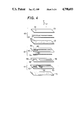
- FIGS. 1 through 4 are exploded perspective views of different forms of a sensing element of an electrochemical device of the invention in the form of an oxygen sensor, respectively;
- FIG. 5 is a schematic elevational view in cross section taken along line V--V of FIG. 4;
- FIG. 6 is an exploded perspective view of another form of a sensing element of the electrochemical device.
- FIG. 7 is a schematic elevational view in cross section taken along line VII--VII of FIG. 6;
- FIG. 8 is an exploded perspective view of a further form of a sensing element of the electrochemical device.
- FIG. 9 is a schematic elevational view in cross section taken along line IX--IX of FIG. 8.
- FIG. 1 There is first shown in an exploded perspective view of FIG. 1 a sensing element in one example of an oxygen-concentration detector which is one embodiment of an electrochemical device of the invention.
- This sensing element of the oxygen-concentration detector or oxygen sensor includes a planar solid electrolyte layer 2 made of zirconia ceramics containing yttria, or the like, a planar spacer layer 4 and a planar support layer 6 which are made of the same solid electrolyte material as the solid electrolyte layer 2.
- planar layers 2, 4 and 6 of solid electrolyte constitute a generally planar or sheet-like solid electrolyte body of laminar structure.
- the spacer layer 4 sandwiched by the solid electrolyte layer 2 and the support layer 6 has an elongate recess 8 formed longitudinally thereof so as to serve as a reference-gas passage 8 in which a reference substance is introduced.
- a porous reference electrode 10 made of platinum, for example, is disposed on one surface of the support layer 6 so that the reference electrode 10 is exposed to the reference substance (reference gas) such as ambient air introduced in the reference-gas passage 8.
- reference substance reference gas
- the reference and measuring electrodes 10, 12 are provided with respective electrical leads 14, 16 which are electrically connected to a suitable external measuring device, so that an electric potential between the two electrodes 10, 12 is measured by the measuring device. More particularly stated, the external measuring device measures an electromotive force which is produced between the measuring electrode 12 exposed to the measurement gas, and the reference electrode 10 exposed to the reference gas (ambient air), due to a difference in oxygen concentration between the measurement gas and the reference gas.
- the outer surface of the solid electrolyte layer 2 on which the measuring electrode 12 is disposed is covered by a porous ceramic layer 18.
- the surface of the support layer 6 opposite to the surface on which the reference electrode 10 is disposed, that is, the outer surface of the support layer 6, is covered with a ceramic layer 20 (porous ceramic layer in this case) made of a ceramic material which has substantially the same shrinkage characteristic during firing thereof, as that of the porous ceramic layer 18.
- the sensing element of the electrochemical device constructed as described above is manufactured in the following manner.
- unfired layers of the electrodes 12, 10 and electrical leads 16, 14 are formed, in a known screen-printing or similar process, on respective unfired green sheets of the solid electrolyte layer 2 and support layer 6.
- a paste of ceramic particles which will form the porous ceramic layers 18, 20 by firing is applied by printing to the outer surfaces of the green sheets of the solid electrolyte layer 2 and support layer 6, before or after the green sheets of the layers 2, 6 and the green sheet of the spacer layer 4 have been superposed into an unfired laminar structure so that the spacer layer 4 is sandwiched by the layers 2 and 6.
- the laminar structure of the green sheets with the ceramic paste applied for formation of the porous ceramic layers 18, 20, is then co-fired in a known manner, whereby the sensing element of the electrochemical device in the form of an oxygen sensor is produced.
- the unfired ceramic layers 18, 20 having substantially the same property of firing shrinkage are formed on the opposite sides of the unfired laminar green-sheet structure of the generally planar solid electrolyte 2, 4, 6 which constitutes an electrochemical cell.
- a stress that acts on one side of the unfired laminar structure to cause warpage in one direction due to a difference in firing shrinkage between the unfired solid electrolyte body 2, 4, 6 and one of the unfired ceramic layers 18, 20 counteracts or counterbalances a stress that acts on the other side of the unfired laminar structure to cause warpage in the other direction due to a difference in firing shrinkage between the unfired solid electrolyte body 2, 4, 6 and the other unfired ceramic layer 18, 20.
- the occurrence of warpage or buckling of the planar electrochemical cell as a whole is effectively restrained.
- the ceramic layer 18 covering the outer surface of the solid electrolyte layer 2 on which the measuring electrode 12 is formed should be of a porous structure so that the measuring electrode 12 is exposed to the measurement gas, such as an exhaust gas, through the porous structure of the ceramic layer 18.
- the porous ceramic layer 18 protects the measuring electrode 12 against direct contact with a flow of the measurement gas.
- the ceramic layer 20 covering the outer surface of the support layer 6, is provided primarily for preventing the warpage of the laminar solid electrolyte body 2, 4, 6 due to the existence of the porous ceramic layer 18.
- the ceramic layer 20 may be either porous or gas-tight, but should however exhibit the firing shrinkage property which is substantially identical to that of the porous ceramic layer 18.
- These two ceramic layers 18, 20 are preferably formed of a ceramic material the major component of which is alumina or spinel.
- the ceramic layers 18, 20 may be made of ceramics whose major component is borosilicate glass, mullite, steatite, forsterite, cordierite, or zircon. Since these ceramic materials have electrically insulating property, the ceramic layers 18, 20 may be suitably used for blocking current leakage from an electrical heater if a layer of the heater is disposed on the ceramic layer 18, 20.
- the firing shrinkage properties of the ceramic layers 18, 20 may be adjusted as needed in a known manner.
- the ceramic material of the same chemical composition is used for both ceramic layers 18, 20, and the shrinkage property is determined by adjusting the particle size, and size distribution of the ceramic particles, and by adjusting an amount of a sintering agent to be added to the ceramic paste.
- the easiest method for giving the ceramic layers 18, 20 the same firing shrinkage property is to use a paste of ceramic particles which is prepared in the same batch.
- the ceramic layers 18, 20 which are made of the ceramic material discussed above, are usually formed so that their porosity is held within an approximate range of 5-30%.
- the solid electrolyte body 2, 4, 6 which forms a substantive part of the electrochemical cell may be made of beta-alumina, aluminum nitride, NASICON, SrCeO 3 , solid solution of bismuth oxide-oxide of rare earth element, La 1-x Ca x YO 3- ⁇ , or the like, in place of the previously indicated zirconia ceramics.
- the electrochemical cell is produced by means of concurrent firing of the unfired layers 2, 4, 6, 18 and 20 as previously described, it is preferred to co-fire the electrodes 10, 12 and and their electrical leads 14, 16 together with the unfired laminar structure of the layers 2, 4, 6, 18 and 20.
- these electrodes and leads are preferably formed by printing, using as major components thereof elements of the platinum group including platinum, palladium, rhodium, iridium, ruthenium and osmium. The printed layers are finally fired to form the intended layers of electrodes and leads.
- an electrochemical sensing element of an electrochemical device of the invention has been described with a certain degree of particularity in connection with the construction and method of manufacture, the invention is by no means limited to the precise disclosure of the above embodiment, but may be applied to other types of electrochemical devices, and other forms of the laminar electrochemical sensing element as illustrated in FIGS. 2 through 9.
- the constructions of the electrochemical sensing elements illustrated in these figures are improved in terms of freedom from current leakage from an electrical heater, operating reliability and durability, as well as in freedom from warpage due to firing shrinkage.
- the oxygen sensing element shown in FIG. 2 further includes a planar electrical heater 22 which is disposed in contact with the porous ceramic layer 20 of the sensing element of FIG. 1.
- the electrical heater 22 comprises a pair of gas-tight ceramic layers 24, 24 each of which has an elongate slit 25 formed in the longitudinal direction, and further comprises a heating portion 30 which is sandwiched by the gas-tight ceramic layers 24, 24.
- the heating portion 30 is embedded in a gas-tight ceramic structure 24, 24.
- the heating portion 30 includes a heating element 26 and a pair of electrical leads 28.
- the material of the gas-tight ceramic layers 24, 24 is selected from known ceramic materials such as zirconia, alumina, mullite, spinel, titania, barium titanate and calcium zirconate. However, it is particularly preferred to use zirconia as a major component of the ceramics for these layers 24, 24.
- the heating element 26 and leads 28, 28 of the heating portion 30 of the electrical heater 22 may be made of elements of the platinum group which includes platinum, palladium, rhodium, iridium, ruthenium and osmium, or of metals having a high melting point such as nickel, tantalum or tungsten, or alloys such as nichrome.
- the heating element 26 and leads 28, 28 are made of a mixture of an element of the platinum group and ceramics such as zirconia, alumina or spinel. With the use of such a mixture, the adhesion of the heating element 26 and leads 28, 28 to the mating surfaces of the gas-tight ceramic layers 24, 24 is improved.
- the mixture of the above-indicated metal and ceramics (in the form of fine particles) is applied in a predetermined pattern on one of the gas-tight ceramic layers 24, 24, and co-fired together with the ceramic layers 24, 24, and with the solid electrolyte body 2, 4, 6 and the porous ceramic layers 18, 20, whereby the integral oxygen sensing element of a laminar structure is obtained.
- reference numberal 32 designates a potentiometer for measuring an electromotive force which is induced between the reference electrode 10 and the measuring electrode 12, based on a difference in oxygen concentration between the reference gas and the measurement gas.
- Electric power from DC power source 32 is applied to the heating portion 30 to cause the heating element 26 to generate heat, and thereby heat a detecting portion of the electrochemical cell at which the electrodes 10, 12 are disposed, so that the sensing portion is maintained at a predetermined elevated operating temperature.
- the conventionally experienced inconvenience of warpage arising from firing shrinkage is effectively restrained by the provision of the ceramic layers 18, 20 having the same firing shrinkage properties which are provided on both sides of the solid electrolyte body 2, 4, 6 which forms the electrochemical cell.
- the provision of the planar electrical heater 22 permits the detecting portion of the cell to be held at its operating temperature, thereby improving the response characteristics of the cell.
- the gas-tight ceramic structure 24, 24 in which the heating element 26 and leads 28, 28 are embedded serves to effectively prevent the metal component (e.g., platinum) of the heating portion 30 from scattering at an elevated temperature, and protect the heating portion 30 against exposure to hot exhaust gas, whereby the possibility of electrical disconnection of the heating element 26 or leads 28, 28 is eliminated.
- the service life of the heater 22, and consequently the oxygen sensing element may be prolonged.
- the electrical heater 22 is co-fired as an integral part of the electrochemical cell, with the porous ceramic layer 20 interposed therebetween. Consequently, a difference in thermal expansion between the support layer 6 and the gas-tight ceramic layer 24 is absorbed by the porous structure of the ceramic layer 20 interposed between the layers 6 and 24, whereby flake-off or cracks of these layers 6, 20, 24 is avoided. Since the support layer 6 is made of zirconia ceramics, the difference in thermal expansion between the layers 6 and 24 may be minimized by using zirconia as a major components of the gas-tight ceramic layers 24. In other words, the use of zirconia ceramics for the ceramic layer 24 contributes to prevention of flake-off of those layers.
- the electrical insulating property of the porous ceramic layer 20 interposed between the electrical heater 22 and the electrochemical cell blocks the flow of current which can leak from the heating portion 30 of the heater 22 toward the electrochemical cell, and obviates unfavourable influence of the leaked current upon the electromotive force of the electrochemical cell, which may lead to inaccurate or erroneous measurement of oxygen concentration of the measurement gas.
- the thickness of the porous ceramic layer 20 between the electrochemical cell and the electrical heater 22 be kept as small as possible to such extent that the ceramic layer 20 may serve as an electrical insulator for the heater 22.
- the thickness of the ceramic layer 20 should be held not greater than 300 microns, and particularly 10-200 microns.
- FIG. 3 there is illustrated another form of an electrochemical sensing element, which is different from that of FIG. 2, in that an anti-warpage layer 36 is formed on the solid electrolyte layer 2 on which the measuring electrode 12 is disposed.
- the anti-warpage layer 36 consists of a porous ceramic layer 18, and a ceramic layer 38 which is made of the same ceramic material as the gas-tight ceramic layers 24, 24.
- the anti-warpage layer 36 acts to prevent not only the warpage of the sensing element that would arise due to the interposition of the porous ceramic layer 20, but also the warpage that would be caused by the existence of the gas-tight ceramic layers 24 of the electrical heater 22.
- the porous ceramic layer 18 and the ceramic layer 38 of the anti-warpage layer 36 have rectangular openings 40 through which the measurement gas is introduced directly to the surface of the measuring electrode 12.
- FIGS. 4 and 5 A further modified oxygen sensing element of the electrochemical device is depicted in FIGS. 4 and 5.
- This sensing element is suitably used as a lean-burn sensor for controlling an engine of the type which emits an exhaust gas of lean air-fuel ratios whose oxygen partial pressure is higher than that of the stoichiometric air-fuel ratio.
- the oxygen sensing element of FIGS. 4 and 5 comprises an electrochemical cell assembly which includes two electrochemical cells, one of which is an oxygen pumping cell 42, and the other of which is an oxygen-concentration sensing cell 44.
- an electrochemical cell assembly which includes two electrochemical cells, one of which is an oxygen pumping cell 42, and the other of which is an oxygen-concentration sensing cell 44.
- On the pumping cell 42 there is provided a planar electrical heater 46 similar to the heater 22 used in the preceding embodiment.
- a porous ceramic layer 48 is interposed between the electrical heater 46 and the pumping cell 42.
- the pumping cell 42 includes a planar solid electrolyte layer 50 which carries, on its outer and inner surfaces, an outer pumping electrode 52 and an inner pumping electrode 54, respectively, such that the outer and inner electrodes 52, 54 are positioned in an aligned opposed relationship with each other.
- These pumping electrodes 52, 54 are connected to an external power source through respective electrical leads, to apply a predetermined voltage across the two pumping electrodes, so that oxygen in an amount proportional to the applied voltage is pumped in the direction of thickness of the solid electrolyte layer 50.
- a spacer layer 56 which has a cavity 58.
- the measurement gas such as an exhaust gas
- the apertures 60 have a small diameter selected to provide a predetermined diffusion resistance.
- the oxygen-concentration sensing cell 44 which is similar in construction to the pumping cell 42, includes a planar solid electrolyte layer 62, a measuring electrode 64 exposed to the measurement gas in the cavity 58, and a reference electrode 68 exposed to the reference gas in a reference-gas passage 66 formed in the spacer layer 56.
- the thus constructed electrochemical sensing cell 44 serves as an oxygen concentration cell.
- the measuring and reference electrodes 64, 68 are electrically connected through respective electrical leads to an external measuring device to measure an electric potential difference between the electrodes 64, 68.
- the sensing cell 44 measures an electromotive force between the measuring electrode 64 exposed to the measurement gas in the cavity 58 in the spacer layer 56, and the reference electrode 68 exposed to the reference gas, based on a difference in oxygen concentration between the measurement gas and the reference gas.
- the electrical heater 46 includes a ceramic gas-tight outermost layer 70 which covers the heating portion 30 and protects the same against exposure to the external measurement gas.
- porous ceramic layer 48 is interposed between the electrical heater 46 and the oxygen pumping cell 42.
- the outer surface of the sensing cell 44 is covered by a porous ceramic layer 72 which is made of ceramics having substantially the same firing shrinkage property as the porous ceramic layer 48.
- the electrically insulating porous ceramic layer 48 disposed between the heater 46 and the electrochemical pumping cell 42 is effective to prevent flake-off of these members, and leakage current from the heater 46.
- the gas-tight ceramic outermost layer 70 of the heater 46 serves as an effective protector for the heating portion 30, that is, protects the same against deterioration due to exposure to the measurement gas, thereby considerably improving the durability of the electrical heater 46.
- the porous ceramic layer 72 disposed on the outer side of the sensing cell 44 cooperates with the porous ceramic layer 48 made of the same material, to avoid otherwise possible warpage or buckling of the sensing element due to concurrent firing of the pumping cell 42, spacer layer 56, sensing cell 44 and electrical heater 46.
- the electrochemical cell assembly 42, 44 is sandwiched on its opposite sides by the porous ceramic layers 48, 72. According to this arrangement, a stress to cause warpage on the side of the porous ceramic layer 48 counteracts a stress to cause warpage on the side of the porous ceramic layer 72, whereby the possibility of warpage of the sensing element as a whole is substantially removed.
- FIGS. 6 and 7 Another modified form of an oxygen sensing element is shown in FIGS. 6 and 7, which is used as a lean-burn sensor similar to that of FIGS. 4 and 5. Unlike the sensing element of FIGS. 4 and 5, however, this modified sensing element has an electrical heater 74 on the outer side of the sensing cell 44, such that the porous ceramic layer 72 is interposed between the heater 74 and the sensing cell 44.
- the heating portion 30 of the electrical heater 74 is disposed on a ceramic support layer 76 of a porous structure, and embedded in a laminar porous ceramic structure 72, 76.
- the laminar porous ceramic structure 72, 76 is covered at its outer surface by a gas-tight ceramic outermost layer 78 and therefore protected against exposure to the external atmosphere.
- the thus constructed electrical heater 74 is co-fired together with the sensing cell 44, the porous ceramic layer 72, and a spacer layer 80 which has the reference-gas passage 66 and which is located on the side of the sensing cell 44 on which the reference electrode 68 is disposed.
- the two porous ceramic layers 48, 72 provided on opposite sides of the cell assembly, which consists of the pumping and sensing cells 42, 44, effectively prevent otherwise possible warpage of the sensing element. Furthermore, the interposition of the porous ceramic layer 72 between the sensing cell 44 and the electrical heater 74 provides a suitable solution to elimination of the flake-off trouble due to thermal expansion difference, and of the current leakage trouble. Moreover, the porous ceramic structure 72, 76 in which the heating portion 30 is embedded, is completely blocked by the gas-tight ceramic layer 78 against exposure to the external measurement gas. That is, the gas-tight ceramic layer 78 protects the heating portion 30 against deterioration due to exposure to the measurement gas.
- FIGS. 8 and 9 there is also illustrated in FIGS. 8 and 9 an oxygen sensor in the form of a lean-burn sensor similar to that shown in FIGS. 6 and 7.
- This sensor is characterized by an additional porous ceramic layer 82 which is interposed between the pumping cell 42 and the sensing cell 44.
- the electrochemical cell assembly 42, 44 is sandwiched by the two porous ceramic layers.
- each of the pumping and sensing cells 42, 44 is sandwiched on its opposite sides by two porous ceramic layers. That is, the porous ceramic layers 72 and 82 are disposed on the opposite sides of the oxygen pumping cell 42, respectively, to prevent warpage of the pumping cell 42.
- the porous ceramic layers 82 and 48 are disposed on opposite sides of the oxygen sensing cell 44, respectively, to prevent warpage of the sensing cell 44.
- the warpage of the sensor as a whole is effectively avoided.
- the materials previously indicated for use in connection with the embodiment of FIG. 1 may be used in the modified embodiments of FIGS. 2-9 for the solid electrolyte layers (50, 56, 62, etc.), porous ceramic layers (48, 72, 76, 82), gas-tight ceramic layers (70, 78), electrodes (52, 54, 64, 68) and their electrical leads.
- unfired laminar structures of the individual sensing elements are prepared in a known lamination or screen-printing process, and the prepared unfired laminar structures are co-fired into the integral planar sensing elements which are used in an electrochemical device.
- two electrical heaters be provided on both sides of an electrochemical cell, rather than a single heater is provided on one side of the cell as in the illustrated embodiments.
- the electrical heater 22, 46, 74 may be energized by either AC or DC current
- the arrangement according to the concept of the invention is advantageous particularly for obviating a problem of current leakage where a DC power supply is used for the electrical heater.
- electrochemical sensing elements are suitably used as oxygen sensors
- the invention may be embodied as other types of sensors or controllers for determining or controlling the concentration of specific components of a fluid associated with electrode reaction, other than oxygen such as nitrogen, carbon dioxide and hydrogen.
- a paste for the electrodes 10, 12 was prepared by adding 8% by weight of ethyl cellulose and 40% by weight of butyl carbitol to a powder mixture which consists of 90% by weight of platinum and 10% by weight of ZrO 2 .
- unfired layers of the reference and measuring electrodes 10, 12 were screen-printed on the corresponding surfaces of the unfired layers 2 and 6, respectively.
- a a paste was prepared by adding 10% by weight of polyvinyl butyral resin, 5% by weight of dibutyl sebacate and 40% by weight of butyl carbitol to a powder mixture which consists of 98% by weight of Al 2 O 3 , 1.5% by weight of SiO 2 and 0.5% by weight of CaO.
- the porous ceramic layer 20 of 30 microns was formed by screen-printing on the surface of the unfired support layer 6 opposite to the surface on which the reference electrode 10 was formed.
- a paste was prepared by adding 8% by weight of polyvinyl butyral resin, 3% by weight of dibutyl sebacate and 40% by weight of butyl carbitol to a powder mixture which consists of 79 mole % of ZrO 2 , 11 mole % of Nb 2 O 3 and 10 mole % of Y 2 O 3 .
- a paste was prepared by adding 8% by weight of ethyl cellulose and 40% by weight of butyl carbitol to a powder mixture which consists of 80% by weight of platinum and 20% by weight of Al 2 O 3 .
- unfired layers of the electrical heater 22 was formed by screen-printing on the outer surface of the unfired ceramic layer 20, such that the heating portion 30 was embedded between the gas-tight ceramic layers 24 each of which has a high electrical resistance and a thickness of 70 microns.
- the unfired ceramic layer 18 was screen-printed by using the same paste as used for forming the porous ceramic layer 20.
- the unfired ceramic layer 38 was then screen-printed on the unfirmed ceramic layer 18, by using the same paste as used for the gas-tight ceramic layer 24.
- the produced oxygen sensing elements exhibited as small as about 0.1 mm warpage over the entire length of 30 mm, that is, exhibited substantially no warpage.
- comparative oxygen sensing elements were produced, without the porous ceramic layer 18, according to a conventional method, for comparison with the above-identified sensing elements produced according to the invention. These comparative sensing elements demonstrated an average warpage of 2 mm over their 30 mm length, such that the electrical heater was convexed outwardly.
- Example 1 With the method as used in Example 1, the five unfired layers 2, 4, 6, 24, 24 of solid electrolyte were formed, and unfired layers of the electrodes 10, 12 and heating portion 30 were formed by screen-printing on the appropriate layers 2, 4 and 24, respectively.
- a paste was prepared by adding 10 parts by weight of polyvinyl butyral resin, 5 parts by weight of dioctyl phthalate, and 100 parts by weight of trichloroethylene (as a solvent) to 100 parts by weight of powder mixture which consists of 98% by weight of MgO ⁇ Al 2 O 3 , 1.5% by weight of SiO 2 and 0.5% by weight of CaO.
- the obtained mixture slurry was cast, in a conventional doctor-blading process, to form the planar unfired ceramic layers 18 and 20 of FIG. 2 such that they have 0.1 mm thickness.
- the sensing elements of EXAMPLE 2 exhibited an average warpage of as little as 0.1 mm over the entire length of 30 mm, namely, substantially no warpage.
Landscapes
- Chemical & Material Sciences (AREA)
- Life Sciences & Earth Sciences (AREA)
- Health & Medical Sciences (AREA)
- Physics & Mathematics (AREA)
- Chemical Kinetics & Catalysis (AREA)
- Electrochemistry (AREA)
- Molecular Biology (AREA)
- Analytical Chemistry (AREA)
- Biochemistry (AREA)
- General Health & Medical Sciences (AREA)
- General Physics & Mathematics (AREA)
- Immunology (AREA)
- Pathology (AREA)
- Measuring Oxygen Concentration In Cells (AREA)
Applications Claiming Priority (2)
| Application Number | Priority Date | Filing Date | Title |
|---|---|---|---|
| JP59-84677 | 1984-04-26 | ||
| JP59084677A JP2502961B2 (ja) | 1984-04-26 | 1984-04-26 | 電気化学的装置の製造方法 |
Related Parent Applications (1)
| Application Number | Title | Priority Date | Filing Date |
|---|---|---|---|
| US06725672 Continuation | 1985-04-22 |
Publications (1)
| Publication Number | Publication Date |
|---|---|
| US4798693A true US4798693A (en) | 1989-01-17 |
Family
ID=13837330
Family Applications (1)
| Application Number | Title | Priority Date | Filing Date |
|---|---|---|---|
| US07/081,631 Expired - Lifetime US4798693A (en) | 1984-04-26 | 1987-08-03 | Method of manufacturing an electrochemical device |
Country Status (4)
| Country | Link |
|---|---|
| US (1) | US4798693A (fr) |
| EP (1) | EP0162603B1 (fr) |
| JP (1) | JP2502961B2 (fr) |
| DE (1) | DE3581765D1 (fr) |
Cited By (72)
| Publication number | Priority date | Publication date | Assignee | Title |
|---|---|---|---|---|
| DE3905298A1 (de) * | 1988-02-22 | 1989-09-28 | Ngk Insulators Ltd | Elektrochemische vorrichtung mit einer einrichtung zum verhindern einer auf heizstromstreuung zurueckzufuehrenden reduktion von festelektrolyt und isolierkeramik |
| US4902400A (en) * | 1986-03-28 | 1990-02-20 | Ngk Insulators, Ltd. | Gas sensing element |
| US4909922A (en) * | 1988-06-02 | 1990-03-20 | Ngk Insulators, Ltd. | Heater-built-in oxygen sensor |
| US4925609A (en) * | 1987-03-02 | 1990-05-15 | Stemcor Corporation | Oxygen-sensing element |
| US4938861A (en) * | 1989-08-01 | 1990-07-03 | Kabushiki Kaisha Riken | Limiting current-type oxygen sensor |
| US5006494A (en) * | 1989-04-24 | 1991-04-09 | Gas Research Institute | Stabilized bismuth oxide |
| US5183801A (en) * | 1989-04-24 | 1993-02-02 | Gas Research Institute | Stabilized bismuth oxide |
| US5238551A (en) * | 1990-10-03 | 1993-08-24 | Ngk Insulators, Ltd. | Oxygen sensor |
| US5427672A (en) * | 1992-07-31 | 1995-06-27 | Hoechst Aktiengesellschaft | Planar sensor made of ceramic material, for detecting combustible gases |
| US5479700A (en) * | 1992-02-28 | 1996-01-02 | Ceramatec, Inc. | Design and manufacturing method for a solid electrolyte ion conducting device |
| US5657532A (en) * | 1996-01-16 | 1997-08-19 | Ferro Corporation | Method of making insulated electrical heating element using LTCC tape |
| US5773894A (en) * | 1993-12-09 | 1998-06-30 | Robert Bosch Gmbh | Insulation layer system for the electrical isolation circuits |
| EP0895593A1 (fr) * | 1997-01-13 | 1999-02-10 | Robert Bosch Gmbh | Element capteur et son procede de fabrication |
| US6270639B1 (en) * | 1998-01-30 | 2001-08-07 | Robert Bosch Gmbh | Electrochemical sensor |
| US6280605B1 (en) * | 1997-12-24 | 2001-08-28 | Robert Bosch Gmbh | Electrochemical sensor |
| EP1191333A1 (fr) * | 2000-07-31 | 2002-03-27 | NGK Spark Plug Company Limited | Elément multicouches de détection de gaz et un capteur de gaz comprenant le-dit élément |
| US20020070111A1 (en) * | 2000-12-07 | 2002-06-13 | Tomio Sugiyama | Gas sensing element |
| US20020094303A1 (en) * | 2000-09-13 | 2002-07-18 | Takatoki Yamamoto | Reactor and process for production thereof |
| US6436277B2 (en) * | 1998-02-09 | 2002-08-20 | Robert Bosch Gmbh | Electrochemical sensor |
| US20030061862A1 (en) * | 2001-10-01 | 2003-04-03 | Tosiharu Kondo | Gas concentration detection element |
| EP1014083A3 (fr) * | 1998-12-21 | 2003-05-02 | Hitachi, Ltd. | Capteur de rapport air-carburant |
| US6579436B2 (en) * | 2000-12-18 | 2003-06-17 | Delphi Technologies, Inc. | Gas sensor and method of producing the same |
| US6579435B2 (en) * | 2000-12-18 | 2003-06-17 | Delphi Technologies, Inc. | Gas sensor |
| US6692700B2 (en) * | 2001-02-14 | 2004-02-17 | Handylab, Inc. | Heat-reduction methods and systems related to microfluidic devices |
| US6746585B2 (en) * | 2000-08-18 | 2004-06-08 | Robert Bosch Gmbh | Gas sensor, especially a lambda probe |
| US20050152808A1 (en) * | 2001-09-12 | 2005-07-14 | Karthik Ganesan | Microfluidic devices having a reduced number of input and output connections |
| US20050160793A1 (en) * | 2002-02-16 | 2005-07-28 | Bernd Schumann | Sensor element, in particular a planar gas sensor element |
| EP1584921A1 (fr) * | 2004-04-01 | 2005-10-12 | Robert Bosch GmbH | Elément chauffant en céramique pour capteurs de gaz |
| US20060166233A1 (en) * | 2004-05-03 | 2006-07-27 | Handylab, Inc. | Method and apparatus for processing polynucleotide-containing samples |
| US20070000780A1 (en) * | 2005-07-01 | 2007-01-04 | Ngk Spark Plug Co., Ltd. | Plural-cell gas sensor with heater |
| US20070114130A1 (en) * | 2005-11-18 | 2007-05-24 | Lankheet Earl W | Gas sensors and methods of manufacture |
| US20070184547A1 (en) * | 2005-10-11 | 2007-08-09 | Kalyan Handique | Polynucleotide sample preparation device |
| US20080050804A1 (en) * | 2001-03-28 | 2008-02-28 | Kalyan Handique | Moving microdroplets in a microfluidic device |
| US20080149840A1 (en) * | 2006-03-24 | 2008-06-26 | Kalyan Handique | Fluorescence Detector for Microfluidic Diagnostic System |
| US20080219894A1 (en) * | 2001-03-28 | 2008-09-11 | Karthik Ganesan | Systems and methods for thermal actuation of microfluidic devices |
| US20080262213A1 (en) * | 2004-05-03 | 2008-10-23 | Betty Wu | Processing Polynucleotide-Containing Samples |
| US20090047713A1 (en) * | 2006-11-14 | 2009-02-19 | Kalyan Handique | Microfluidic Cartridge and Method of Making Same |
| US20090113378A1 (en) * | 2007-10-30 | 2009-04-30 | International Business Machines Corporation | Extending unified process and method content to include dynamic and collaborative content |
| US20090130719A1 (en) * | 2007-07-13 | 2009-05-21 | Handylab, Inc. | Microfluidic Cartridge |
| US20090129978A1 (en) * | 2007-07-13 | 2009-05-21 | Handylab, Inc. | Reagent holder, and kits containing same |
| US20090130745A1 (en) * | 2007-07-13 | 2009-05-21 | Handylab, Inc. | Integrated Apparatus for Performing Nucleic Acid Extraction and Diagnostic Testing on Multiple Biological Samples |
| US20090136386A1 (en) * | 2007-07-13 | 2009-05-28 | Handylab, Inc. | Rack for Sample Tubes and Reagent Holders |
| US20090221059A1 (en) * | 2007-07-13 | 2009-09-03 | Handylab, Inc. | Integrated apparatus for performing nucleic acid extraction and diagnostic testing on multiple biological samples |
| EP2105729A1 (fr) | 2008-03-28 | 2009-09-30 | Ngk Insulator, Ltd. | Capteur de gaz, capteur de NOx et procédé de fabrication de capteur de gaz |
| US20100009351A1 (en) * | 2008-07-11 | 2010-01-14 | Handylab, Inc. | Polynucleotide Capture Materials, and Method of Using Same |
| US20110027151A1 (en) * | 2007-07-13 | 2011-02-03 | Handylab, Inc. | Reagent tube |
| US20110207140A1 (en) * | 2006-03-24 | 2011-08-25 | Kalyan Handique | Microfluidic system for amplifying and detecting polynucleotides in parallel |
| US8088616B2 (en) | 2006-03-24 | 2012-01-03 | Handylab, Inc. | Heater unit for microfluidic diagnostic system |
| CN102376378A (zh) * | 2010-08-19 | 2012-03-14 | 比亚迪股份有限公司 | 一种加热电极浆料和加热电极、以及含有该加热电极的片式氧传感器 |
| USD665095S1 (en) | 2008-07-11 | 2012-08-07 | Handylab, Inc. | Reagent holder |
| US8287820B2 (en) | 2007-07-13 | 2012-10-16 | Handylab, Inc. | Automated pipetting apparatus having a combined liquid pump and pipette head system |
| USD669191S1 (en) | 2008-07-14 | 2012-10-16 | Handylab, Inc. | Microfluidic cartridge |
| US8473104B2 (en) | 2001-03-28 | 2013-06-25 | Handylab, Inc. | Methods and systems for control of microfluidic devices |
| USD692162S1 (en) | 2011-09-30 | 2013-10-22 | Becton, Dickinson And Company | Single piece reagent holder |
| US8617905B2 (en) | 1995-09-15 | 2013-12-31 | The Regents Of The University Of Michigan | Thermal microvalves |
| US20140042025A1 (en) * | 2012-08-09 | 2014-02-13 | Ngk Spark Plug Co., Ltd. | Gas sensor |
| US8679831B2 (en) | 2003-07-31 | 2014-03-25 | Handylab, Inc. | Processing particle-containing samples |
| US20140339080A1 (en) * | 2013-05-15 | 2014-11-20 | Robert Bosch Gmbh | Micromechanical sensor device |
| US8895311B1 (en) | 2001-03-28 | 2014-11-25 | Handylab, Inc. | Methods and systems for control of general purpose microfluidic devices |
| US9040288B2 (en) | 2006-03-24 | 2015-05-26 | Handylab, Inc. | Integrated system for processing microfluidic samples, and method of using the same |
| US20150212035A1 (en) * | 2014-01-24 | 2015-07-30 | Ngk Spark Plug Co., Ltd. | Gas sensor element and gas sensor |
| US9222954B2 (en) | 2011-09-30 | 2015-12-29 | Becton, Dickinson And Company | Unitized reagent strip |
| US9618139B2 (en) | 2007-07-13 | 2017-04-11 | Handylab, Inc. | Integrated heater and magnetic separator |
| USD787087S1 (en) | 2008-07-14 | 2017-05-16 | Handylab, Inc. | Housing |
| US9765389B2 (en) | 2011-04-15 | 2017-09-19 | Becton, Dickinson And Company | Scanning real-time microfluidic thermocycler and methods for synchronized thermocycling and scanning optical detection |
| US20190154626A1 (en) * | 2017-11-22 | 2019-05-23 | Delphi Technologies Ip Limited | Gas sensor with a pump cell |
| US10822644B2 (en) | 2012-02-03 | 2020-11-03 | Becton, Dickinson And Company | External files for distribution of molecular diagnostic tests and determination of compatibility between tests |
| US10900066B2 (en) | 2006-03-24 | 2021-01-26 | Handylab, Inc. | Microfluidic system for amplifying and detecting polynucleotides in parallel |
| US20210033556A1 (en) * | 2017-05-18 | 2021-02-04 | Heraeus Nexensos Gmbh | Sensor for determining gas parameters |
| USD953183S1 (en) * | 2019-11-01 | 2022-05-31 | Nvent Services Gmbh | Fuel sensor |
| US11453906B2 (en) | 2011-11-04 | 2022-09-27 | Handylab, Inc. | Multiplexed diagnostic detection apparatus and methods |
| US11806718B2 (en) | 2006-03-24 | 2023-11-07 | Handylab, Inc. | Fluorescence detector for microfluidic diagnostic system |
Families Citing this family (14)
| Publication number | Priority date | Publication date | Assignee | Title |
|---|---|---|---|---|
| JPH0646189B2 (ja) * | 1985-01-25 | 1994-06-15 | 株式会社日立製作所 | 酸素濃度センサ |
| DE3673563D1 (de) * | 1985-04-19 | 1990-09-27 | Hitachi Ltd | Sauerstoffuehlerelement und verfahren zum herstellen desselben. |
| JPH0668483B2 (ja) * | 1985-10-26 | 1994-08-31 | 日本碍子株式会社 | 電気化学的装置 |
| JPH0640094B2 (ja) * | 1986-03-17 | 1994-05-25 | 日本碍子株式会社 | 電気化学的装置 |
| JPH0810211B2 (ja) * | 1986-09-05 | 1996-01-31 | 日本碍子株式会社 | ガスセンサ及びその製造法 |
| JPH0618292Y2 (ja) * | 1987-12-07 | 1994-05-11 | 株式会社ユニシアジェックス | ヒータ付酸素センサ |
| JP2814027B2 (ja) * | 1990-11-15 | 1998-10-22 | 日本特殊陶業株式会社 | バイオセンサ |
| US5384030A (en) * | 1994-02-15 | 1995-01-24 | General Motors Corporation | Exhaust sensor including a composite tile sensing element and methods of making the same |
| JP4229565B2 (ja) * | 2000-02-29 | 2009-02-25 | 株式会社豊田中央研究所 | NOxセンサ |
| JP2002071628A (ja) * | 2000-06-16 | 2002-03-12 | Ngk Spark Plug Co Ltd | 積層型ガスセンサ素子及びその製造方法並びにこれを備えるガスセンサ |
| JP4588853B2 (ja) * | 2000-08-31 | 2010-12-01 | 日本特殊陶業株式会社 | 積層型ガスセンサ素子の製造方法 |
| JP2003344348A (ja) * | 2002-05-23 | 2003-12-03 | Kyocera Corp | 酸素センサ素子 |
| CN102608193B (zh) * | 2012-04-10 | 2013-09-25 | 无锡隆盛科技股份有限公司 | 一种平板式氧传感器及其制备方法 |
| DE102014007753A1 (de) * | 2014-05-23 | 2015-11-26 | Steinmüller Babcock Environment Gmbh | Korrosionssonde und Verfahren zum Einbau einer Korrosionssonde |
Citations (12)
| Publication number | Priority date | Publication date | Assignee | Title |
|---|---|---|---|---|
| US3978006A (en) * | 1972-02-10 | 1976-08-31 | Robert Bosch G.M.B.H. | Methods for producing oxygen-sensing element, particularly for use with internal combustion engine exhaust emission analysis |
| US4021326A (en) * | 1972-06-02 | 1977-05-03 | Robert Bosch G.M.B.H. | Electro-chemical sensor |
| FR2449887A1 (fr) * | 1979-02-23 | 1980-09-19 | Bosch Gmbh Robert | Detecteur electrochimique de mesure pour determiner la teneur en oxygene dans des gaz, notamment dans les gaz d'echappement de moteurs a combustion |
| GB2054868A (en) * | 1979-07-14 | 1981-02-18 | Bosch Gmbh Robert | Electrochemical measuring sensor for determining the oxygen content of gases |
| US4304652A (en) * | 1979-06-12 | 1981-12-08 | Nissan Motor Company, Limited | Device for detection of air/fuel ratio from oxygen partial pressure in exhaust gas |
| EP0064666A1 (fr) * | 1981-05-12 | 1982-11-17 | Nissan Motor Co., Ltd. | Procédé de fabrication d'un substrat en céramique ayant un conducteur chauffant produit par utilisation d'une pâte conductrice |
| US4402820A (en) * | 1981-08-05 | 1983-09-06 | Nippondenso Co., Ltd. | Oxygen analyzer |
| US4449919A (en) * | 1980-07-10 | 1984-05-22 | Tokyo Shibaura Denki Kabushiki Kaisha | Gas combustion apparatus capable of detecting environmental oxygen deficiency |
| US4498968A (en) * | 1983-03-29 | 1985-02-12 | Ngk Spark Plug Co., Ltd. | Oxygen sensor |
| US4502939A (en) * | 1980-05-10 | 1985-03-05 | Robert Bosch Gmbh | Electrochemical oxygen sensor, particularly for analysis of combustion cases from internal combustion engines |
| US4505806A (en) * | 1981-12-21 | 1985-03-19 | Ngk Spark Plug Co., Ltd. | Oxygen sensor |
| US4505807A (en) * | 1982-02-22 | 1985-03-19 | Ngk Spark Plug Co., Ltd. | Oxygen sensor |
Family Cites Families (5)
| Publication number | Priority date | Publication date | Assignee | Title |
|---|---|---|---|---|
| IT1089129B (it) * | 1976-12-15 | 1985-06-18 | Uop Inc | Cella elettrochimica avente un elettrolita solido a superficie accresciuta e procedimento per prepararla |
| JPS6017060B2 (ja) * | 1979-05-25 | 1985-04-30 | 日産自動車株式会社 | 膜構造酸素センサ素子の製造方法 |
| JPS5958356A (ja) * | 1982-09-28 | 1984-04-04 | Fuji Electric Corp Res & Dev Ltd | ガス分析機器の製造方法 |
| JPS6036948A (ja) * | 1983-08-09 | 1985-02-26 | Ngk Insulators Ltd | 電気化学的装置 |
| JPS60108745A (ja) * | 1983-11-18 | 1985-06-14 | Ngk Insulators Ltd | 電気化学的装置 |
-
1984
- 1984-04-26 JP JP59084677A patent/JP2502961B2/ja not_active Expired - Lifetime
-
1985
- 1985-04-25 DE DE8585302914T patent/DE3581765D1/de not_active Expired - Lifetime
- 1985-04-25 EP EP85302914A patent/EP0162603B1/fr not_active Expired - Lifetime
-
1987
- 1987-08-03 US US07/081,631 patent/US4798693A/en not_active Expired - Lifetime
Patent Citations (13)
| Publication number | Priority date | Publication date | Assignee | Title |
|---|---|---|---|---|
| US3978006A (en) * | 1972-02-10 | 1976-08-31 | Robert Bosch G.M.B.H. | Methods for producing oxygen-sensing element, particularly for use with internal combustion engine exhaust emission analysis |
| US4021326A (en) * | 1972-06-02 | 1977-05-03 | Robert Bosch G.M.B.H. | Electro-chemical sensor |
| FR2449887A1 (fr) * | 1979-02-23 | 1980-09-19 | Bosch Gmbh Robert | Detecteur electrochimique de mesure pour determiner la teneur en oxygene dans des gaz, notamment dans les gaz d'echappement de moteurs a combustion |
| US4334974A (en) * | 1979-02-23 | 1982-06-15 | Robert Bosch Gmbh | Electrochemical oxygen sensor, particularly for use with exhaust gases of internal combustion engines, and especially for polarographic application |
| US4304652A (en) * | 1979-06-12 | 1981-12-08 | Nissan Motor Company, Limited | Device for detection of air/fuel ratio from oxygen partial pressure in exhaust gas |
| GB2054868A (en) * | 1979-07-14 | 1981-02-18 | Bosch Gmbh Robert | Electrochemical measuring sensor for determining the oxygen content of gases |
| US4502939A (en) * | 1980-05-10 | 1985-03-05 | Robert Bosch Gmbh | Electrochemical oxygen sensor, particularly for analysis of combustion cases from internal combustion engines |
| US4449919A (en) * | 1980-07-10 | 1984-05-22 | Tokyo Shibaura Denki Kabushiki Kaisha | Gas combustion apparatus capable of detecting environmental oxygen deficiency |
| EP0064666A1 (fr) * | 1981-05-12 | 1982-11-17 | Nissan Motor Co., Ltd. | Procédé de fabrication d'un substrat en céramique ayant un conducteur chauffant produit par utilisation d'une pâte conductrice |
| US4402820A (en) * | 1981-08-05 | 1983-09-06 | Nippondenso Co., Ltd. | Oxygen analyzer |
| US4505806A (en) * | 1981-12-21 | 1985-03-19 | Ngk Spark Plug Co., Ltd. | Oxygen sensor |
| US4505807A (en) * | 1982-02-22 | 1985-03-19 | Ngk Spark Plug Co., Ltd. | Oxygen sensor |
| US4498968A (en) * | 1983-03-29 | 1985-02-12 | Ngk Spark Plug Co., Ltd. | Oxygen sensor |
Cited By (192)
| Publication number | Priority date | Publication date | Assignee | Title |
|---|---|---|---|---|
| US4902400A (en) * | 1986-03-28 | 1990-02-20 | Ngk Insulators, Ltd. | Gas sensing element |
| US4925609A (en) * | 1987-03-02 | 1990-05-15 | Stemcor Corporation | Oxygen-sensing element |
| DE3905298A1 (de) * | 1988-02-22 | 1989-09-28 | Ngk Insulators Ltd | Elektrochemische vorrichtung mit einer einrichtung zum verhindern einer auf heizstromstreuung zurueckzufuehrenden reduktion von festelektrolyt und isolierkeramik |
| US5028309A (en) * | 1988-02-22 | 1991-07-02 | Ngk Insulators, Ltd. | Electrochemical device incorporating means for preventing reduction of solid electrolyte and insulating ceramics due to heater current leakage |
| US4909922A (en) * | 1988-06-02 | 1990-03-20 | Ngk Insulators, Ltd. | Heater-built-in oxygen sensor |
| US5006494A (en) * | 1989-04-24 | 1991-04-09 | Gas Research Institute | Stabilized bismuth oxide |
| US5183801A (en) * | 1989-04-24 | 1993-02-02 | Gas Research Institute | Stabilized bismuth oxide |
| US4938861A (en) * | 1989-08-01 | 1990-07-03 | Kabushiki Kaisha Riken | Limiting current-type oxygen sensor |
| US5238551A (en) * | 1990-10-03 | 1993-08-24 | Ngk Insulators, Ltd. | Oxygen sensor |
| US5479700A (en) * | 1992-02-28 | 1996-01-02 | Ceramatec, Inc. | Design and manufacturing method for a solid electrolyte ion conducting device |
| US5427672A (en) * | 1992-07-31 | 1995-06-27 | Hoechst Aktiengesellschaft | Planar sensor made of ceramic material, for detecting combustible gases |
| US5773894A (en) * | 1993-12-09 | 1998-06-30 | Robert Bosch Gmbh | Insulation layer system for the electrical isolation circuits |
| US8617905B2 (en) | 1995-09-15 | 2013-12-31 | The Regents Of The University Of Michigan | Thermal microvalves |
| US5657532A (en) * | 1996-01-16 | 1997-08-19 | Ferro Corporation | Method of making insulated electrical heating element using LTCC tape |
| EP0895593A1 (fr) * | 1997-01-13 | 1999-02-10 | Robert Bosch Gmbh | Element capteur et son procede de fabrication |
| US6280605B1 (en) * | 1997-12-24 | 2001-08-28 | Robert Bosch Gmbh | Electrochemical sensor |
| US6270639B1 (en) * | 1998-01-30 | 2001-08-07 | Robert Bosch Gmbh | Electrochemical sensor |
| US6436277B2 (en) * | 1998-02-09 | 2002-08-20 | Robert Bosch Gmbh | Electrochemical sensor |
| EP1014083A3 (fr) * | 1998-12-21 | 2003-05-02 | Hitachi, Ltd. | Capteur de rapport air-carburant |
| EP1191333A1 (fr) * | 2000-07-31 | 2002-03-27 | NGK Spark Plug Company Limited | Elément multicouches de détection de gaz et un capteur de gaz comprenant le-dit élément |
| US6746586B2 (en) | 2000-07-31 | 2004-06-08 | Ngk Spark Plug Co., Ltd. | Multi-layer gas sensor element and gas sensor comprising the same |
| US6746585B2 (en) * | 2000-08-18 | 2004-06-08 | Robert Bosch Gmbh | Gas sensor, especially a lambda probe |
| EP1309852B1 (fr) * | 2000-08-18 | 2009-07-22 | Robert Bosch Gmbh | Capteur de gaz, notamment sonde lambda |
| US20020094303A1 (en) * | 2000-09-13 | 2002-07-18 | Takatoki Yamamoto | Reactor and process for production thereof |
| US7189367B2 (en) * | 2000-09-13 | 2007-03-13 | Riken | Reactor and process for production thereof |
| US6949175B2 (en) | 2000-12-07 | 2005-09-27 | Denso Corporation | Gas sensing element |
| EP1213582A3 (fr) * | 2000-12-07 | 2003-12-17 | Denso Corporation | Elément capteur de gaz |
| US20020070111A1 (en) * | 2000-12-07 | 2002-06-13 | Tomio Sugiyama | Gas sensing element |
| US6579436B2 (en) * | 2000-12-18 | 2003-06-17 | Delphi Technologies, Inc. | Gas sensor and method of producing the same |
| US6579435B2 (en) * | 2000-12-18 | 2003-06-17 | Delphi Technologies, Inc. | Gas sensor |
| US8110158B2 (en) | 2001-02-14 | 2012-02-07 | Handylab, Inc. | Heat-reduction methods and systems related to microfluidic devices |
| US8734733B2 (en) | 2001-02-14 | 2014-05-27 | Handylab, Inc. | Heat-reduction methods and systems related to microfluidic devices |
| US20040219070A1 (en) * | 2001-02-14 | 2004-11-04 | Handylab, Inc., A Delaware Corporation | Heat-reduction methods and systems related to microfluidic devices |
| US20110038768A1 (en) * | 2001-02-14 | 2011-02-17 | Kalyan Handique | Heat-reduction methods and systems related to microfluidic devices |
| US8440149B2 (en) | 2001-02-14 | 2013-05-14 | Handylab, Inc. | Heat-reduction methods and systems related to microfluidic devices |
| US9528142B2 (en) | 2001-02-14 | 2016-12-27 | Handylab, Inc. | Heat-reduction methods and systems related to microfluidic devices |
| US6692700B2 (en) * | 2001-02-14 | 2004-02-17 | Handylab, Inc. | Heat-reduction methods and systems related to microfluidic devices |
| US9051604B2 (en) | 2001-02-14 | 2015-06-09 | Handylab, Inc. | Heat-reduction methods and systems related to microfluidic devices |
| US7332130B2 (en) | 2001-02-14 | 2008-02-19 | Handylab, Inc. | Heat-reduction methods and systems related to microfluidic devices |
| US10351901B2 (en) | 2001-03-28 | 2019-07-16 | Handylab, Inc. | Systems and methods for thermal actuation of microfluidic devices |
| US8894947B2 (en) | 2001-03-28 | 2014-11-25 | Handylab, Inc. | Systems and methods for thermal actuation of microfluidic devices |
| US20080219894A1 (en) * | 2001-03-28 | 2008-09-11 | Karthik Ganesan | Systems and methods for thermal actuation of microfluidic devices |
| US8768517B2 (en) | 2001-03-28 | 2014-07-01 | Handylab, Inc. | Methods and systems for control of microfluidic devices |
| US20080050804A1 (en) * | 2001-03-28 | 2008-02-28 | Kalyan Handique | Moving microdroplets in a microfluidic device |
| US8703069B2 (en) | 2001-03-28 | 2014-04-22 | Handylab, Inc. | Moving microdroplets in a microfluidic device |
| US8895311B1 (en) | 2001-03-28 | 2014-11-25 | Handylab, Inc. | Methods and systems for control of general purpose microfluidic devices |
| US8473104B2 (en) | 2001-03-28 | 2013-06-25 | Handylab, Inc. | Methods and systems for control of microfluidic devices |
| US10619191B2 (en) | 2001-03-28 | 2020-04-14 | Handylab, Inc. | Systems and methods for thermal actuation of microfluidic devices |
| US10571935B2 (en) | 2001-03-28 | 2020-02-25 | Handylab, Inc. | Methods and systems for control of general purpose microfluidic devices |
| US9259735B2 (en) | 2001-03-28 | 2016-02-16 | Handylab, Inc. | Methods and systems for control of microfluidic devices |
| US8420015B2 (en) | 2001-03-28 | 2013-04-16 | Handylab, Inc. | Systems and methods for thermal actuation of microfluidic devices |
| US8273308B2 (en) | 2001-03-28 | 2012-09-25 | Handylab, Inc. | Moving microdroplets in a microfluidic device |
| US9677121B2 (en) | 2001-03-28 | 2017-06-13 | Handylab, Inc. | Systems and methods for thermal actuation of microfluidic devices |
| US7829025B2 (en) | 2001-03-28 | 2010-11-09 | Venture Lending & Leasing Iv, Inc. | Systems and methods for thermal actuation of microfluidic devices |
| US20050152808A1 (en) * | 2001-09-12 | 2005-07-14 | Karthik Ganesan | Microfluidic devices having a reduced number of input and output connections |
| US8043581B2 (en) | 2001-09-12 | 2011-10-25 | Handylab, Inc. | Microfluidic devices having a reduced number of input and output connections |
| US7674431B2 (en) | 2001-09-12 | 2010-03-09 | Handylab, Inc. | Microfluidic devices having a reduced number of input and output connections |
| US8685341B2 (en) | 2001-09-12 | 2014-04-01 | Handylab, Inc. | Microfluidic devices having a reduced number of input and output connections |
| US8323584B2 (en) | 2001-09-12 | 2012-12-04 | Handylab, Inc. | Method of controlling a microfluidic device having a reduced number of input and output connections |
| US9028773B2 (en) | 2001-09-12 | 2015-05-12 | Handylab, Inc. | Microfluidic devices having a reduced number of input and output connections |
| US20100158754A1 (en) * | 2001-09-12 | 2010-06-24 | Handylab, Inc. | Microfluidic devices having a reduced number of input and output connections |
| US20030061862A1 (en) * | 2001-10-01 | 2003-04-03 | Tosiharu Kondo | Gas concentration detection element |
| US20050160793A1 (en) * | 2002-02-16 | 2005-07-28 | Bernd Schumann | Sensor element, in particular a planar gas sensor element |
| US11078523B2 (en) | 2003-07-31 | 2021-08-03 | Handylab, Inc. | Processing particle-containing samples |
| US10865437B2 (en) | 2003-07-31 | 2020-12-15 | Handylab, Inc. | Processing particle-containing samples |
| US12139745B2 (en) | 2003-07-31 | 2024-11-12 | Handylab, Inc. | Processing particle-containing samples |
| US8679831B2 (en) | 2003-07-31 | 2014-03-25 | Handylab, Inc. | Processing particle-containing samples |
| US9670528B2 (en) | 2003-07-31 | 2017-06-06 | Handylab, Inc. | Processing particle-containing samples |
| US10731201B2 (en) | 2003-07-31 | 2020-08-04 | Handylab, Inc. | Processing particle-containing samples |
| EP1584921A1 (fr) * | 2004-04-01 | 2005-10-12 | Robert Bosch GmbH | Elément chauffant en céramique pour capteurs de gaz |
| US10604788B2 (en) | 2004-05-03 | 2020-03-31 | Handylab, Inc. | System for processing polynucleotide-containing samples |
| US10364456B2 (en) | 2004-05-03 | 2019-07-30 | Handylab, Inc. | Method for processing polynucleotide-containing samples |
| US20060166233A1 (en) * | 2004-05-03 | 2006-07-27 | Handylab, Inc. | Method and apparatus for processing polynucleotide-containing samples |
| US8852862B2 (en) | 2004-05-03 | 2014-10-07 | Handylab, Inc. | Method for processing polynucleotide-containing samples |
| US20080262213A1 (en) * | 2004-05-03 | 2008-10-23 | Betty Wu | Processing Polynucleotide-Containing Samples |
| US11441171B2 (en) | 2004-05-03 | 2022-09-13 | Handylab, Inc. | Method for processing polynucleotide-containing samples |
| US10494663B1 (en) | 2004-05-03 | 2019-12-03 | Handylab, Inc. | Method for processing polynucleotide-containing samples |
| US8470586B2 (en) | 2004-05-03 | 2013-06-25 | Handylab, Inc. | Processing polynucleotide-containing samples |
| US10443088B1 (en) | 2004-05-03 | 2019-10-15 | Handylab, Inc. | Method for processing polynucleotide-containing samples |
| US20070000780A1 (en) * | 2005-07-01 | 2007-01-04 | Ngk Spark Plug Co., Ltd. | Plural-cell gas sensor with heater |
| US8012325B2 (en) * | 2005-07-01 | 2011-09-06 | Ngk Spark Plug Co., Ltd. | Plural-cell gas sensor with heater |
| US20070184547A1 (en) * | 2005-10-11 | 2007-08-09 | Kalyan Handique | Polynucleotide sample preparation device |
| US20070114130A1 (en) * | 2005-11-18 | 2007-05-24 | Lankheet Earl W | Gas sensors and methods of manufacture |
| US10913061B2 (en) | 2006-03-24 | 2021-02-09 | Handylab, Inc. | Integrated system for processing microfluidic samples, and method of using the same |
| US11142785B2 (en) | 2006-03-24 | 2021-10-12 | Handylab, Inc. | Microfluidic system for amplifying and detecting polynucleotides in parallel |
| US12162007B2 (en) | 2006-03-24 | 2024-12-10 | Handylab, Inc. | Integrated system for processing microfluidic samples, and method of using same |
| US10821436B2 (en) | 2006-03-24 | 2020-11-03 | Handylab, Inc. | Integrated system for processing microfluidic samples, and method of using the same |
| US11666903B2 (en) | 2006-03-24 | 2023-06-06 | Handylab, Inc. | Integrated system for processing microfluidic samples, and method of using same |
| US9802199B2 (en) | 2006-03-24 | 2017-10-31 | Handylab, Inc. | Fluorescence detector for microfluidic diagnostic system |
| US12458972B2 (en) | 2006-03-24 | 2025-11-04 | Handylab, Inc. | Fluorescence detector for microfluidic diagnostic system |
| US20110207140A1 (en) * | 2006-03-24 | 2011-08-25 | Kalyan Handique | Microfluidic system for amplifying and detecting polynucleotides in parallel |
| US20110210257A9 (en) * | 2006-03-24 | 2011-09-01 | Kalyan Handique | Fluorescence Detector for Microfluidic Diagnostic System |
| US8088616B2 (en) | 2006-03-24 | 2012-01-03 | Handylab, Inc. | Heater unit for microfluidic diagnostic system |
| US10799862B2 (en) | 2006-03-24 | 2020-10-13 | Handylab, Inc. | Integrated system for processing microfluidic samples, and method of using same |
| US10821446B1 (en) | 2006-03-24 | 2020-11-03 | Handylab, Inc. | Fluorescence detector for microfluidic diagnostic system |
| US8323900B2 (en) | 2006-03-24 | 2012-12-04 | Handylab, Inc. | Microfluidic system for amplifying and detecting polynucleotides in parallel |
| US8883490B2 (en) | 2006-03-24 | 2014-11-11 | Handylab, Inc. | Fluorescence detector for microfluidic diagnostic system |
| US10695764B2 (en) | 2006-03-24 | 2020-06-30 | Handylab, Inc. | Fluorescence detector for microfluidic diagnostic system |
| US20080149840A1 (en) * | 2006-03-24 | 2008-06-26 | Kalyan Handique | Fluorescence Detector for Microfluidic Diagnostic System |
| US10843188B2 (en) | 2006-03-24 | 2020-11-24 | Handylab, Inc. | Integrated system for processing microfluidic samples, and method of using the same |
| US10857535B2 (en) | 2006-03-24 | 2020-12-08 | Handylab, Inc. | Integrated system for processing microfluidic samples, and method of using same |
| US9040288B2 (en) | 2006-03-24 | 2015-05-26 | Handylab, Inc. | Integrated system for processing microfluidic samples, and method of using the same |
| US11959126B2 (en) | 2006-03-24 | 2024-04-16 | Handylab, Inc. | Microfluidic system for amplifying and detecting polynucleotides in parallel |
| US9080207B2 (en) | 2006-03-24 | 2015-07-14 | Handylab, Inc. | Microfluidic system for amplifying and detecting polynucleotides in parallel |
| US10900066B2 (en) | 2006-03-24 | 2021-01-26 | Handylab, Inc. | Microfluidic system for amplifying and detecting polynucleotides in parallel |
| US11085069B2 (en) | 2006-03-24 | 2021-08-10 | Handylab, Inc. | Microfluidic system for amplifying and detecting polynucleotides in parallel |
| US11141734B2 (en) | 2006-03-24 | 2021-10-12 | Handylab, Inc. | Fluorescence detector for microfluidic diagnostic system |
| US11806718B2 (en) | 2006-03-24 | 2023-11-07 | Handylab, Inc. | Fluorescence detector for microfluidic diagnostic system |
| US8765076B2 (en) | 2006-11-14 | 2014-07-01 | Handylab, Inc. | Microfluidic valve and method of making same |
| US20090047713A1 (en) * | 2006-11-14 | 2009-02-19 | Kalyan Handique | Microfluidic Cartridge and Method of Making Same |
| US8709787B2 (en) | 2006-11-14 | 2014-04-29 | Handylab, Inc. | Microfluidic cartridge and method of using same |
| US10710069B2 (en) | 2006-11-14 | 2020-07-14 | Handylab, Inc. | Microfluidic valve and method of making same |
| US9815057B2 (en) | 2006-11-14 | 2017-11-14 | Handylab, Inc. | Microfluidic cartridge and method of making same |
| US12030050B2 (en) | 2006-11-14 | 2024-07-09 | Handylab, Inc. | Microfluidic cartridge and method of making same |
| US12128405B2 (en) | 2006-11-14 | 2024-10-29 | Handylab, Inc. | Microfluidic valve and method of making same |
| US20100173393A1 (en) * | 2006-11-14 | 2010-07-08 | Handy Lab, Inc. | Microfluidic valve and method of making same |
| US20090130745A1 (en) * | 2007-07-13 | 2009-05-21 | Handylab, Inc. | Integrated Apparatus for Performing Nucleic Acid Extraction and Diagnostic Testing on Multiple Biological Samples |
| US11254927B2 (en) | 2007-07-13 | 2022-02-22 | Handylab, Inc. | Polynucleotide capture materials, and systems using same |
| US9618139B2 (en) | 2007-07-13 | 2017-04-11 | Handylab, Inc. | Integrated heater and magnetic separator |
| US12397295B2 (en) | 2007-07-13 | 2025-08-26 | Handylab, Inc. | Integrated apparatus for performing nucleic acid extraction and diagnostic testing on multiple biological samples |
| US9701957B2 (en) | 2007-07-13 | 2017-07-11 | Handylab, Inc. | Reagent holder, and kits containing same |
| US20090130719A1 (en) * | 2007-07-13 | 2009-05-21 | Handylab, Inc. | Microfluidic Cartridge |
| US20090129978A1 (en) * | 2007-07-13 | 2009-05-21 | Handylab, Inc. | Reagent holder, and kits containing same |
| US9347586B2 (en) | 2007-07-13 | 2016-05-24 | Handylab, Inc. | Automated pipetting apparatus having a combined liquid pump and pipette head system |
| US20090136386A1 (en) * | 2007-07-13 | 2009-05-28 | Handylab, Inc. | Rack for Sample Tubes and Reagent Holders |
| US12128402B2 (en) | 2007-07-13 | 2024-10-29 | Handylab, Inc. | Microfluidic cartridge |
| US20090221059A1 (en) * | 2007-07-13 | 2009-09-03 | Handylab, Inc. | Integrated apparatus for performing nucleic acid extraction and diagnostic testing on multiple biological samples |
| US10065185B2 (en) | 2007-07-13 | 2018-09-04 | Handylab, Inc. | Microfluidic cartridge |
| US10071376B2 (en) | 2007-07-13 | 2018-09-11 | Handylab, Inc. | Integrated apparatus for performing nucleic acid extraction and diagnostic testing on multiple biological samples |
| US11845081B2 (en) | 2007-07-13 | 2023-12-19 | Handylab, Inc. | Integrated apparatus for performing nucleic acid extraction and diagnostic testing on multiple biological samples |
| US10100302B2 (en) | 2007-07-13 | 2018-10-16 | Handylab, Inc. | Polynucleotide capture materials, and methods of using same |
| US11549959B2 (en) | 2007-07-13 | 2023-01-10 | Handylab, Inc. | Automated pipetting apparatus having a combined liquid pump and pipette head system |
| US10139012B2 (en) | 2007-07-13 | 2018-11-27 | Handylab, Inc. | Integrated heater and magnetic separator |
| US10179910B2 (en) | 2007-07-13 | 2019-01-15 | Handylab, Inc. | Rack for sample tubes and reagent holders |
| US10234474B2 (en) | 2007-07-13 | 2019-03-19 | Handylab, Inc. | Automated pipetting apparatus having a combined liquid pump and pipette head system |
| US11466263B2 (en) | 2007-07-13 | 2022-10-11 | Handylab, Inc. | Diagnostic apparatus to extract nucleic acids including a magnetic assembly and a heater assembly |
| US9259734B2 (en) | 2007-07-13 | 2016-02-16 | Handylab, Inc. | Integrated apparatus for performing nucleic acid extraction and diagnostic testing on multiple biological samples |
| US9238223B2 (en) | 2007-07-13 | 2016-01-19 | Handylab, Inc. | Microfluidic cartridge |
| US20110027151A1 (en) * | 2007-07-13 | 2011-02-03 | Handylab, Inc. | Reagent tube |
| US9217143B2 (en) | 2007-07-13 | 2015-12-22 | Handylab, Inc. | Polynucleotide capture materials, and methods of using same |
| US9186677B2 (en) | 2007-07-13 | 2015-11-17 | Handylab, Inc. | Integrated apparatus for performing nucleic acid extraction and diagnostic testing on multiple biological samples |
| US10590410B2 (en) | 2007-07-13 | 2020-03-17 | Handylab, Inc. | Polynucleotide capture materials, and methods of using same |
| US11266987B2 (en) | 2007-07-13 | 2022-03-08 | Handylab, Inc. | Microfluidic cartridge |
| US8105783B2 (en) | 2007-07-13 | 2012-01-31 | Handylab, Inc. | Microfluidic cartridge |
| US10625262B2 (en) | 2007-07-13 | 2020-04-21 | Handylab, Inc. | Integrated apparatus for performing nucleic acid extraction and diagnostic testing on multiple biological samples |
| US10625261B2 (en) | 2007-07-13 | 2020-04-21 | Handylab, Inc. | Integrated apparatus for performing nucleic acid extraction and diagnostic testing on multiple biological samples |
| US10632466B1 (en) | 2007-07-13 | 2020-04-28 | Handylab, Inc. | Integrated apparatus for performing nucleic acid extraction and diagnostic testing on multiple biological samples |
| US8133671B2 (en) | 2007-07-13 | 2012-03-13 | Handylab, Inc. | Integrated apparatus for performing nucleic acid extraction and diagnostic testing on multiple biological samples |
| US8710211B2 (en) | 2007-07-13 | 2014-04-29 | Handylab, Inc. | Polynucleotide capture materials, and methods of using same |
| US10717085B2 (en) | 2007-07-13 | 2020-07-21 | Handylab, Inc. | Integrated apparatus for performing nucleic acid extraction and diagnostic testing on multiple biological samples |
| US8182763B2 (en) | 2007-07-13 | 2012-05-22 | Handylab, Inc. | Rack for sample tubes and reagent holders |
| US11060082B2 (en) | 2007-07-13 | 2021-07-13 | Handy Lab, Inc. | Polynucleotide capture materials, and systems using same |
| US8216530B2 (en) | 2007-07-13 | 2012-07-10 | Handylab, Inc. | Reagent tube |
| US10875022B2 (en) | 2007-07-13 | 2020-12-29 | Handylab, Inc. | Integrated apparatus for performing nucleic acid extraction and diagnostic testing on multiple biological samples |
| US8287820B2 (en) | 2007-07-13 | 2012-10-16 | Handylab, Inc. | Automated pipetting apparatus having a combined liquid pump and pipette head system |
| US8415103B2 (en) | 2007-07-13 | 2013-04-09 | Handylab, Inc. | Microfluidic cartridge |
| US10844368B2 (en) | 2007-07-13 | 2020-11-24 | Handylab, Inc. | Diagnostic apparatus to extract nucleic acids including a magnetic assembly and a heater assembly |
| US8324372B2 (en) | 2007-07-13 | 2012-12-04 | Handylab, Inc. | Polynucleotide capture materials, and methods of using same |
| US20090113378A1 (en) * | 2007-10-30 | 2009-04-30 | International Business Machines Corporation | Extending unified process and method content to include dynamic and collaborative content |
| US20090242400A1 (en) * | 2008-03-28 | 2009-10-01 | Ngk Insulators, Ltd. | GAS SENSOR, NOx SENSOR AND METHOD OF MANUFACTURING GAS SENSOR |
| US9816958B2 (en) | 2008-03-28 | 2017-11-14 | Ngk Insulators, Ltd. | Gas sensor, NOx sensor and method of manufacturing gas sensor |
| EP2105729A1 (fr) | 2008-03-28 | 2009-09-30 | Ngk Insulator, Ltd. | Capteur de gaz, capteur de NOx et procédé de fabrication de capteur de gaz |
| USD665095S1 (en) | 2008-07-11 | 2012-08-07 | Handylab, Inc. | Reagent holder |
| US20100009351A1 (en) * | 2008-07-11 | 2010-01-14 | Handylab, Inc. | Polynucleotide Capture Materials, and Method of Using Same |
| USD669191S1 (en) | 2008-07-14 | 2012-10-16 | Handylab, Inc. | Microfluidic cartridge |
| USD787087S1 (en) | 2008-07-14 | 2017-05-16 | Handylab, Inc. | Housing |
| CN102376378B (zh) * | 2010-08-19 | 2013-08-21 | 比亚迪股份有限公司 | 一种加热电极浆料和加热电极、以及含有该加热电极的片式氧传感器 |
| CN102376378A (zh) * | 2010-08-19 | 2012-03-14 | 比亚迪股份有限公司 | 一种加热电极浆料和加热电极、以及含有该加热电极的片式氧传感器 |
| US9765389B2 (en) | 2011-04-15 | 2017-09-19 | Becton, Dickinson And Company | Scanning real-time microfluidic thermocycler and methods for synchronized thermocycling and scanning optical detection |
| US10781482B2 (en) | 2011-04-15 | 2020-09-22 | Becton, Dickinson And Company | Scanning real-time microfluidic thermocycler and methods for synchronized thermocycling and scanning optical detection |
| US11788127B2 (en) | 2011-04-15 | 2023-10-17 | Becton, Dickinson And Company | Scanning real-time microfluidic thermocycler and methods for synchronized thermocycling and scanning optical detection |
| US9222954B2 (en) | 2011-09-30 | 2015-12-29 | Becton, Dickinson And Company | Unitized reagent strip |
| US10076754B2 (en) | 2011-09-30 | 2018-09-18 | Becton, Dickinson And Company | Unitized reagent strip |
| USD905269S1 (en) | 2011-09-30 | 2020-12-15 | Becton, Dickinson And Company | Single piece reagent holder |
| US9480983B2 (en) | 2011-09-30 | 2016-11-01 | Becton, Dickinson And Company | Unitized reagent strip |
| USD1029291S1 (en) | 2011-09-30 | 2024-05-28 | Becton, Dickinson And Company | Single piece reagent holder |
| USD692162S1 (en) | 2011-09-30 | 2013-10-22 | Becton, Dickinson And Company | Single piece reagent holder |
| USD831843S1 (en) | 2011-09-30 | 2018-10-23 | Becton, Dickinson And Company | Single piece reagent holder |
| USD742027S1 (en) | 2011-09-30 | 2015-10-27 | Becton, Dickinson And Company | Single piece reagent holder |
| US11453906B2 (en) | 2011-11-04 | 2022-09-27 | Handylab, Inc. | Multiplexed diagnostic detection apparatus and methods |
| US10822644B2 (en) | 2012-02-03 | 2020-11-03 | Becton, Dickinson And Company | External files for distribution of molecular diagnostic tests and determination of compatibility between tests |
| US20140042025A1 (en) * | 2012-08-09 | 2014-02-13 | Ngk Spark Plug Co., Ltd. | Gas sensor |
| US9494548B2 (en) * | 2012-08-09 | 2016-11-15 | Ngk Spark Plug Co., Ltd. | Gas sensor |
| US20140339080A1 (en) * | 2013-05-15 | 2014-11-20 | Robert Bosch Gmbh | Micromechanical sensor device |
| US9880125B2 (en) * | 2013-05-15 | 2018-01-30 | Robert Bosch Gmbh | Micromechanical sensor device |
| US20150212035A1 (en) * | 2014-01-24 | 2015-07-30 | Ngk Spark Plug Co., Ltd. | Gas sensor element and gas sensor |
| US10012611B2 (en) * | 2014-01-24 | 2018-07-03 | Ngk Spark Plug Co., Ltd. | Gas sensor element and gas sensor |
| US20210033556A1 (en) * | 2017-05-18 | 2021-02-04 | Heraeus Nexensos Gmbh | Sensor for determining gas parameters |
| US10859526B2 (en) * | 2017-11-22 | 2020-12-08 | Delphi Technologies Ip Limited | Gas sensor with a pump cell |
| US20190154626A1 (en) * | 2017-11-22 | 2019-05-23 | Delphi Technologies Ip Limited | Gas sensor with a pump cell |
| USD953183S1 (en) * | 2019-11-01 | 2022-05-31 | Nvent Services Gmbh | Fuel sensor |
| USD979435S1 (en) | 2019-11-01 | 2023-02-28 | Nvent Services Gmbh | Fuel sensor |
Also Published As
| Publication number | Publication date |
|---|---|
| EP0162603B1 (fr) | 1991-02-20 |
| JPS60228955A (ja) | 1985-11-14 |
| DE3581765D1 (de) | 1991-03-28 |
| EP0162603A3 (en) | 1988-01-27 |
| EP0162603A2 (fr) | 1985-11-27 |
| JP2502961B2 (ja) | 1996-05-29 |
Similar Documents
| Publication | Publication Date | Title |
|---|---|---|
| EP0162603B1 (fr) | Dispositif électrochimique et méthode de fabrication | |
| EP0188900B1 (fr) | Dispositif électrochimique | |
| EP0144185B1 (fr) | Dispositif électrochimique | |
| EP0310206B1 (fr) | Dispositif électrochimique | |
| EP0259175B1 (fr) | Détecteur de gaz et son procédé de fabrication | |
| US5169513A (en) | Electrochemical element and method of making | |
| US4655901A (en) | Oxygen sensor element | |
| US4559126A (en) | Electrochemical device | |
| EP0142992B1 (fr) | Dispositif électrochimique comportant un capteur | |
| EP0172746B1 (fr) | Dispositif électrochimique | |
| EP0294085B1 (fr) | Eléments électrochimiques | |
| EP0171910B1 (fr) | Méthode de fabrication d'une cellule électrochimique | |
| US4797194A (en) | Electrochemical element | |
| US5787866A (en) | Air-fuel ratio sensor | |
| EP0987548B1 (fr) | Capteur de gaz | |
| EP1014083A2 (fr) | Capteur de rapport air-carburant | |
| EP0168938B1 (fr) | Elément électrochimique | |
| US20020100697A1 (en) | Gas sensor with uniform heating and method of making same | |
| JP2851632B2 (ja) | 電気化学的素子 | |
| US20060049049A1 (en) | Sensor element | |
| JP2002131278A (ja) | センサ素子 | |
| JPH0426055B2 (fr) | ||
| JPH01253646A (ja) | 空燃比検出素子及びその製造方法 |
Legal Events
| Date | Code | Title | Description |
|---|---|---|---|
| STCF | Information on status: patent grant |
Free format text: PATENTED CASE |
|
| FEPP | Fee payment procedure |
Free format text: PAYOR NUMBER ASSIGNED (ORIGINAL EVENT CODE: ASPN); ENTITY STATUS OF PATENT OWNER: LARGE ENTITY |
|
| FPAY | Fee payment |
Year of fee payment: 4 |
|
| FPAY | Fee payment |
Year of fee payment: 8 |
|
| FPAY | Fee payment |
Year of fee payment: 12 |