US4815280A - Thermal flow meter - Google Patents
Thermal flow meter Download PDFInfo
- Publication number
- US4815280A US4815280A US07/049,147 US4914787A US4815280A US 4815280 A US4815280 A US 4815280A US 4914787 A US4914787 A US 4914787A US 4815280 A US4815280 A US 4815280A
- Authority
- US
- United States
- Prior art keywords
- pair
- sensor
- sensor coils
- conduit
- support projections
- Prior art date
- Legal status (The legal status is an assumption and is not a legal conclusion. Google has not performed a legal analysis and makes no representation as to the accuracy of the status listed.)
- Expired - Lifetime
Links
Images




Classifications
-
- G—PHYSICS
- G01—MEASURING; TESTING
- G01F—MEASURING VOLUME, VOLUME FLOW, MASS FLOW OR LIQUID LEVEL; METERING BY VOLUME
- G01F1/00—Measuring the volume flow or mass flow of fluid or fluent solid material wherein the fluid passes through a meter in a continuous flow
- G01F1/68—Measuring the volume flow or mass flow of fluid or fluent solid material wherein the fluid passes through a meter in a continuous flow by using thermal effects
-
- G—PHYSICS
- G01—MEASURING; TESTING
- G01F—MEASURING VOLUME, VOLUME FLOW, MASS FLOW OR LIQUID LEVEL; METERING BY VOLUME
- G01F1/00—Measuring the volume flow or mass flow of fluid or fluent solid material wherein the fluid passes through a meter in a continuous flow
- G01F1/68—Measuring the volume flow or mass flow of fluid or fluent solid material wherein the fluid passes through a meter in a continuous flow by using thermal effects
- G01F1/684—Structural arrangements; Mounting of elements, e.g. in relation to fluid flow
- G01F1/6847—Structural arrangements; Mounting of elements, e.g. in relation to fluid flow where sensing or heating elements are not disturbing the fluid flow, e.g. elements mounted outside the flow duct
Definitions
- a flow meter of this type has been frequently installed in a feed passage of gases used in the manufacture of semiconductors but since high boiling substances contained in said gases are adhered to an inner wall of the conduit after the use for a long time according to circumstances, it is necessary to remove said high boiling point substances by baking out with flowing inert gases, such as nitrogen, through the conduit or depressurizing whenever occasion arises.
- This baking out operation is carried out by heating the conduit up to an appointed temperature.
- a ribbon heater is wound around the peripheral surface of a case including said conduit therein or a heater (for example "POSISTER” (trade name) manufactured by Murata Works, Co., Ltd.), which is formed of a self temperature control type resistor having a positive resistance temperature coefficient whose resistance value is suddenly increased at a certain design temperature or more, is closely mounted on the peripheral surface of said case including said conduit therein.
- POSISTER trade name
- the conduit 50 is adapted to be covered by the enveloping member 56 and the outside enveloping member 58 other than said enveloping member 56, whereby the enveloping member 56 is thermally connected with the conduit 50, so that it takes a considerably long time for a temperature of the conduit 50 to reach a temperature required for the baking out operation and as a result, it is difficult to efficiently carry out the baking out operation in a short time even though the outside enveloping member 58 is heated by for example the ribbon heater wound around the peripheral surface thereof.
- conduit 50 and the sensor coils 51, 52 surrounding said conduit 50 are adapted to be doubly enveloped by the enveloping member 56 and the outside enveloping member 58, so that the problems occur also in that the construction of taking out a lead wire and the like are complicated in addition to the inferior workability and the expensiveness.
- the present invention was achieved in view of the above described matters. It is an object of the present invention to provide a thermal flow meter which is simple in construction and capable of surely carrying out the baking out operation in a short time and easily carrying out the assembling and the like.
- a thermal flow meter comprising a conduit, through which a fluid flows, whose peripheral surface is surrounded by a pair of sensor coils according to the present invention is characterized by that a sensor case is formed of two block members made of heat conductive materials and at least one of said block members is provided with a pair of support projections formed integrally with said block member in the vicinity of both ends of the sensor coils on an inner surface thereof to hold said conduit by means of said support projections.
- FIGS. 1 to 4 One preferred embodiment of the present invention is shown in FIGS. 1 to 4, in which
- FIG. 2 is a side sectional view
- FIG. 3 is a sectional view showing a state of sensor coils wound around a conduit.
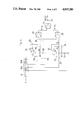
- FIG. 4 is a block circuit diagram.
- FIG. 5 is a perspective view showing the block member according to another preferred embodiment of the present invention.
- FIG. 6 is a block circuit diagram according to further another preferred embodiment of the present invention.
- FIG. 7 is a sectional view for describing the prior art.
- reference numeral 1 designates a sensor case comprising two split block members 2, 2 having a symmetrical shape.
- Reference numeral 3 designates heat conductive adhesives made of epoxy resins and the like containing silver and the like to be applied on the splicing surface of said block members 2, 2.
- the block members 2, 2 are provided with a pair of support projections 4, 4 formed integrally therewith at suitable intervals on an inner surface thereof.
- Reference numeral 5 designates a bridge portion formed across the support projections 4, 4 so as to thermally communicate the support projections 4, 4 with each other.
- the block members 2, 2 are provided with the support members 4, 4 and the bridge portion 5 formed integrally therewith on an inner surface thereof.
- the support projections 4, 4 are provided with dented portions 7, 7 for holding a conduit 6, which will be mentioned later, formed on an upper surface thereof.
- Said sensor case 1 is formed of heat conductive materials, for example, epoxy resins comprising silver powders or metals such as aluminium and stainless steel.
- the conduit 6 is formed of an almost reverse U letter-shaped metallic pipe made of stainless steel and the like and put in said dented portions 7, 7 under the condition that it is inserted through bases 8, 8 made of stainless steel and the like at both ends 6a, 6b thereof so that a sample fluid F may flow through the conduit 6 in the direction of an arrow.
- Reference numerals 9, 9 designate heat conductive adhesives made of epoxy resins and the like comprising silver and the like used for reinforcing the thermal connection between the conduit 6 and the support projection 4.
- the sensor coils 10A, 10B designate a pair of self heating type sensor coils wound around the peripheral surface of the conduit 6 between the support projections 4, 4 of the conduit 6.
- the sensor coils 10A, 10B are formed in a four-layer construction by folding the end portions thereof three times so that the winding-starting positions and the winding-finishing positions (for example, 10a, 10a designate the winding-starting sides while 10b, 10b designate the winding-finishing sides) thereof may be positioned in the midst of both sensor coils 10A, 10B.
- the sensor coils 10A, 10B are thermally connected with the conduit 6 (electrically insulated).
- the end portions of the sides of the sensor coils 10A, 10B are positioned so as to be adjacent to said support projections 4, 4 as far as such positioning is possible.
- These sensor coils 10A, 10B ar formed of a heat sensitive resistance wire having a large temperature coefficient made of Fe-Ni alloys and the like.
- reference numeral 11 designates a layer formed of silicone varnishes, polyimide varnishes and the like for fixing and preventing the sensor coils 10A, 10B wound in the above described manner from getting loose, and so as to coat the sensor coils 10A, 10B.
- Reference numeral 12 designates a lead stand made of heat-resisting materials such as ceramics, polyimide resins and polyamide resins provided with a plurality of electrically conductive portions 13 --formed on one side thereof by metallizing.
- Reference numeral 16 designates a thermal insulating material, such as quartz glass wool, put in an inner space 17 opened in one side (the lower side in FIG. 1) only and closed in other three sides so as to be filled in the circumference of the conduit 6 between the support projections 4, 4 and a pair of sensor coils 10A, 10B wound around the conduit 6.
- Reference numerals 18, 18 designate metallic sealing members to be put in a groove formed in a lower end surface of the bases 8, 8.
- Reference numerals 19, 20 designate constant temperature control circuits comprising said sensor coils 10A, 10B as constituent elements of bridge circuits 24, 30, which will be mentioned later, respectively. Both the circuit 19 and the circuit 20 are constructed from the same parts and control so that a temperature of said sensor coil 10A may be always equal to that of said sensor coil 10B and they may be always constant.
- the constant temperature control circuit 19 is provided with the bridge circuit 24 comprising the sensor coil 10A, a temperature-setting resistance 21 for the sensor coil 10A and bridge resistances 22, 23 and a control circuit 25.
- the constant temperature control circuit 20 is provided with a bridge circuit 30 comprising the sensor coil 10B, a temperature-setting resistance 26 for the sensor coil 10B, bridge resistances 27, 28 and a variable resistance 29 and a control circuit 31.
- variable resistance 29 is controlled so that an output from said bridge circuit 24 may be equal to that from said bridge circuit 30.
- temperature coefficients of said resistances 21, 22, 23, 26, 27, 28 29 are set so as to be sufficiently small in comparison with those of said sensor coils 10A, 10B.
- a 1 , a 2 each designates an output point of the bridge circuit 24, 30, respectively.
- b 1 , b 2 each designates a joint of the resistance 22 with the resistance 23 and that of the resistance 27 with the resistance 28 (strictly speaking, the variable resistance 29), respectively.
- Said control circuit 25 compares an electric potential at the output point a 1 with that at the joint b 1 to put out an output to the bridge circuit 24 when there is a difference between both electric potentials, whereby maintaining an equilibrium of said circuit 24. Also said control circuit 31 acts so as to maintain an equilibrium of the bridge circuit 30 on the basis of electric potentials at the output point a 2 and the joint b 2 in the same manner as in said control circuit 25.
- Reference numeral 32 and 33 designates an adding circuit and a subtracting circuit, respectively, which receives electric potentials V 1 , V 2 put out from the output points a 1 , a 2 as inputs.
- the former puts out V 1 +V 2 as an adding output while the latter puts out V 1 -V 2 as a subtracting output.
- Reference numeral 34 designates a dividing circuit for receiving the adding output from said adding circuit 32 and the subtracting output from said subtracting circuit 33 as inputs to put out (V 1 -V 2 )/(V 1 +V 2 ) as a dividing output.
- reference numeral 35 designates an output terminal.
- the temperature of the sensor coil 10A, 10B is set at the value determined by the temperature-setting resistance 21, 26 of the bridge circuit 24, 30, respectively. And, since the characteristics of said temperature-setting resistance 21 are set so as to be equal to those of said temperature-setting resistance 26, the temperature of said sensor coil 10A becomes equal to that of said sensor coil 10B. A a result, the output V 1 from the output point a 1 becomes equal to the output V 2 from the output point a 2 . Accordingly, an output from the output terminal 35 becomes zero, which shows that the fluid F is not flowing.
- V 1 , V 2 are put in the adding circuit 32 and the subtracting circuit 33.
- the adding circuit 32 and the subtracting circuit 33 puts out the adding output V 1 +V 2 and the subtracting output V 1 -V 2 , respectively.
- These outputs are put in the dividing circuit 34 where the appointed division is carried out to put out the dividing output (V 1 -V 2 )/(V 1 +V 2 ).
- the support projections 4, 4 for holding the conduit 6 surrounded by the sensor coils 10A, 10B in a thermally connected manner are formed integrally with the block members 2, 2 and thermally connected with each other also by means of the bridge portion 5, there is little difference of temperature between an upstream side point P and a downstream side point Q of the sensor coils 10A, 10B and as a result, the time required for achieving thermal equilibrium is shortened, whereby improving the responsiveness.
- the sensor coils 10A, 10B can always operate under the stabilized temperature condition and correspond merely to the change of the flow rate of the fluid flowing through the conduit 6, whereby the flow rate of the fluid can be correctly measured.
- the block members 2, 2, that is to say the sensor case 1 are heated to heat said conduit 6 up to the appointed temperature during the baking out operation, whereby the desired baking out operation can be efficiently carried out in a short time.
- the sensor coils 10A, 10B are wound around the peripheral surface of the conduit 6 between the support projections 4, 4, the lead wires of the sensor coils 10A, 10B can be easily taken out.
- the block members 2, 2 constructing the sensor case 1 are remarkably simple in construction, so that the manufacturing cost can be remarkably reduced.
- the lengths of the sensor coils 10A, 10B in the direction of the conduit 6 can be reduced and the temperature distribution is steepened all over the sensor coils 10A, 10B, whereby the response speed can be increased so much as that.
- the winding construction of the sensor coils 10A, 10B is not limited to the four-layer construction. 2n-layer (n is natural numbers) constructions may be used.
- the lead stand 12 is provided with a plurality of electrically conductive portions 13 and the electrical connection is carried out through these electrically conductive portions 13, the positions of connecting the sensor coils 10A, 10B with the electrically conductive portions 13 can be suitably changed.
- FIG. 5 showing another preferred embodiment of the present invention
- a pair of support projections 4, 4 are formed integrally with the block members 2, 2 at a suitable interval.
- the preferred embodiment as shown in FIG. 5 is different from the above described preferred embodiment in absence of the bridge portion 5. Also in this preferred embodiment the similar effect as in the above described preferred embodiment can be achieved.
- the self heating type sensor coils 10A, 10B are used but a separated heating type sensor coil may be used.
- the sensor case is formed of two block members made of heat conductive materials, at least one of said block members being provided with a pair of support projections formed integrally with said block member adjacent to both ends of the sensor coil on the inner surface thereof to hold said conduit by means of said support projections, not only the sensor coil can operate under the always stabilized temperature environment but also the baking out operation can be surely carried out in a short time.
- the sensor case is simple in construction, the lead wires can be easily taken out and also the manufacturing cost can be reduced.
- a gas phase can be prevented from being mixed with a liquid phase in the conduit during the measurement of flow rate, so that also an effect of surely capable of heating can be achieved even in the case where the sensor case is heated from the outside.
Landscapes
- Physics & Mathematics (AREA)
- Fluid Mechanics (AREA)
- General Physics & Mathematics (AREA)
- Measuring Volume Flow (AREA)
Applications Claiming Priority (2)
| Application Number | Priority Date | Filing Date | Title |
|---|---|---|---|
| JP61121877A JPH0676897B2 (ja) | 1986-05-27 | 1986-05-27 | 熱式流量計 |
| JP61-121877 | 1986-05-27 |
Publications (1)
| Publication Number | Publication Date |
|---|---|
| US4815280A true US4815280A (en) | 1989-03-28 |
Family
ID=14822133
Family Applications (1)
| Application Number | Title | Priority Date | Filing Date |
|---|---|---|---|
| US07/049,147 Expired - Lifetime US4815280A (en) | 1986-05-27 | 1987-05-13 | Thermal flow meter |
Country Status (3)
| Country | Link |
|---|---|
| US (1) | US4815280A (ja) |
| JP (1) | JPH0676897B2 (ja) |
| KR (1) | KR940000140B1 (ja) |
Cited By (25)
| Publication number | Priority date | Publication date | Assignee | Title |
|---|---|---|---|---|
| WO1992020006A3 (en) * | 1991-04-26 | 1992-12-23 | Unit Instr Inc | Thermal mass flow sensor |
| US5398549A (en) * | 1991-06-13 | 1995-03-21 | Mks Japan, Inc. | Flowmeter sensor |
| US5410912A (en) * | 1991-06-13 | 1995-05-02 | Mks Japan, Inc. | Mass flow sensor |
| EP0809090A1 (en) * | 1996-05-23 | 1997-11-26 | Varian Associates, Inc. | Fluid thermal mass flow sensor |
| US5892149A (en) * | 1996-05-24 | 1999-04-06 | I F M Electronic Gmbh | Heat transfer monitoring and/or measuring device |
| WO1999021067A3 (en) * | 1997-10-17 | 1999-10-28 | Faramarz Frank Azima | Mass flow controller and related methods |
| US6062077A (en) * | 1997-10-17 | 2000-05-16 | Azima; Faramarz | Techniques for making and using a sensing assembly for a mass flow controller |
| US6125695A (en) * | 1997-10-13 | 2000-10-03 | Teledyne Brown Engineering, Inc. | Method and apparatus for measuring a fluid |
| US6244293B1 (en) | 1997-07-15 | 2001-06-12 | Faramarz Azima | Fluid mass flow controller device and method |
| US6474700B2 (en) | 1996-10-30 | 2002-11-05 | Unit Instruments, Inc. | Gas panel |
| US6539792B2 (en) | 2000-02-14 | 2003-04-01 | Unit Instruments | Method and apparatus for balancing resistance |
| US6639506B1 (en) * | 1998-12-28 | 2003-10-28 | Lansense, Llc | Method and apparatus for sensing and measuring plural physical properties, including temperature |
| US20040100289A1 (en) * | 2002-07-19 | 2004-05-27 | Celerity Group, Inc. | Variable resistance sensor with common reference leg |
| NL1032007C2 (nl) * | 2006-06-14 | 2007-12-17 | Berkin Bv | Stromingssensor van het thermische type. |
| US20080196494A1 (en) * | 2007-02-21 | 2008-08-21 | Isao Suzuki | Flow sensor |
| US20100313976A1 (en) * | 2009-06-10 | 2010-12-16 | Vistadeltek, Llc | Extreme flow rate and/or high temperature fluid delivery substrates |
| EP1615001A3 (en) * | 2000-03-30 | 2011-01-19 | Berkin B.V. | Mass flowmeter |
| US20110232588A1 (en) * | 2010-03-26 | 2011-09-29 | Msp Corporation | Integrated system for vapor generation and thin film deposition |
| US8307854B1 (en) | 2009-05-14 | 2012-11-13 | Vistadeltek, Inc. | Fluid delivery substrates for building removable standard fluid delivery sticks |
| CN111982220A (zh) * | 2019-05-22 | 2020-11-24 | 比尔克特韦尔克有限两合公司 | 质量流传感器组件以及用于制造质量流传感器组件的方法 |
| CN112649058A (zh) * | 2017-03-22 | 2021-04-13 | A.O.史密斯公司 | 具有热膜风速计的流量传感器 |
| WO2022025762A1 (en) | 2020-07-30 | 2022-02-03 | Berkin B.V. | Thermal-type flow sensor with a thermally conductive frame element in the form of a printed circuit board (pcb) |
| US11262226B2 (en) | 2020-02-17 | 2022-03-01 | GWU Design | Hybrid mass flow sensor including a thermal and coriolis principle measurement arrangements |
| US11543275B2 (en) * | 2017-03-30 | 2023-01-03 | Fujikin Incorporated | Mass flow sensor, mass flow meter including the mass flow sensor, and mass flow controller including the mass flow sensor |
| US12546639B2 (en) * | 2020-12-22 | 2026-02-10 | Beijing Aurasky Electronics Co., Ltd. | Fluid measurement sensor and mass flow controller |
Families Citing this family (2)
| Publication number | Priority date | Publication date | Assignee | Title |
|---|---|---|---|---|
| KR100735753B1 (ko) | 2005-10-04 | 2007-07-06 | 삼성전자주식회사 | 공유된 비트라인을 갖는 플래쉬 메모리 소자 및 그의제조방법 |
| JP4805091B2 (ja) * | 2006-10-24 | 2011-11-02 | 株式会社堀場エステック | 熱式質量流量センサ及びマスフローコントローラ |
Citations (7)
| Publication number | Priority date | Publication date | Assignee | Title |
|---|---|---|---|---|
| US2594618A (en) * | 1945-08-11 | 1952-04-29 | Atomic Energy Commission | Thermal flowmeter |
| US2729976A (en) * | 1946-05-21 | 1956-01-10 | Laub John Harry | Thermal flowmeter |
| US3827299A (en) * | 1971-06-09 | 1974-08-06 | Perkin Elmer Ltd | Electrical flow-meters |
| US4517838A (en) * | 1982-11-12 | 1985-05-21 | Ohkura Electric Co., Ltd. | Thermal mass flow meter |
| US4548075A (en) * | 1984-02-02 | 1985-10-22 | Dresser Industries, Inc. | Fast responsive flowmeter transducer |
| JPH06262220A (ja) * | 1993-03-12 | 1994-09-20 | Sumitomo Metal Ind Ltd | 熱間継目無管製造用マンドレルバー |
| JPH06262221A (ja) * | 1993-03-09 | 1994-09-20 | Hitachi Ltd | 鉄鋼材の熱間圧延設備 |
-
1986
- 1986-05-27 JP JP61121877A patent/JPH0676897B2/ja not_active Expired - Lifetime
-
1987
- 1987-05-13 US US07/049,147 patent/US4815280A/en not_active Expired - Lifetime
- 1987-05-27 KR KR1019870005288A patent/KR940000140B1/ko not_active Expired - Lifetime
Patent Citations (7)
| Publication number | Priority date | Publication date | Assignee | Title |
|---|---|---|---|---|
| US2594618A (en) * | 1945-08-11 | 1952-04-29 | Atomic Energy Commission | Thermal flowmeter |
| US2729976A (en) * | 1946-05-21 | 1956-01-10 | Laub John Harry | Thermal flowmeter |
| US3827299A (en) * | 1971-06-09 | 1974-08-06 | Perkin Elmer Ltd | Electrical flow-meters |
| US4517838A (en) * | 1982-11-12 | 1985-05-21 | Ohkura Electric Co., Ltd. | Thermal mass flow meter |
| US4548075A (en) * | 1984-02-02 | 1985-10-22 | Dresser Industries, Inc. | Fast responsive flowmeter transducer |
| JPH06262221A (ja) * | 1993-03-09 | 1994-09-20 | Hitachi Ltd | 鉄鋼材の熱間圧延設備 |
| JPH06262220A (ja) * | 1993-03-12 | 1994-09-20 | Sumitomo Metal Ind Ltd | 熱間継目無管製造用マンドレルバー |
Cited By (35)
| Publication number | Priority date | Publication date | Assignee | Title |
|---|---|---|---|---|
| WO1992020006A3 (en) * | 1991-04-26 | 1992-12-23 | Unit Instr Inc | Thermal mass flow sensor |
| US5398549A (en) * | 1991-06-13 | 1995-03-21 | Mks Japan, Inc. | Flowmeter sensor |
| US5410912A (en) * | 1991-06-13 | 1995-05-02 | Mks Japan, Inc. | Mass flow sensor |
| EP0809090A1 (en) * | 1996-05-23 | 1997-11-26 | Varian Associates, Inc. | Fluid thermal mass flow sensor |
| US5792952A (en) * | 1996-05-23 | 1998-08-11 | Varian Associates, Inc. | Fluid thermal mass flow sensor |
| US5892149A (en) * | 1996-05-24 | 1999-04-06 | I F M Electronic Gmbh | Heat transfer monitoring and/or measuring device |
| US6474700B2 (en) | 1996-10-30 | 2002-11-05 | Unit Instruments, Inc. | Gas panel |
| US6244293B1 (en) | 1997-07-15 | 2001-06-12 | Faramarz Azima | Fluid mass flow controller device and method |
| US6125695A (en) * | 1997-10-13 | 2000-10-03 | Teledyne Brown Engineering, Inc. | Method and apparatus for measuring a fluid |
| US6062077A (en) * | 1997-10-17 | 2000-05-16 | Azima; Faramarz | Techniques for making and using a sensing assembly for a mass flow controller |
| WO1999021067A3 (en) * | 1997-10-17 | 1999-10-28 | Faramarz Frank Azima | Mass flow controller and related methods |
| US6639506B1 (en) * | 1998-12-28 | 2003-10-28 | Lansense, Llc | Method and apparatus for sensing and measuring plural physical properties, including temperature |
| US6539792B2 (en) | 2000-02-14 | 2003-04-01 | Unit Instruments | Method and apparatus for balancing resistance |
| EP1615001A3 (en) * | 2000-03-30 | 2011-01-19 | Berkin B.V. | Mass flowmeter |
| US6845659B2 (en) | 2002-07-19 | 2005-01-25 | Celerity Group, Inc. | Variable resistance sensor with common reference leg |
| US20050092077A1 (en) * | 2002-07-19 | 2005-05-05 | Celerity Group, Inc. | Variable resistance sensor with common reference leg |
| US7082824B2 (en) | 2002-07-19 | 2006-08-01 | Celerity, Inc. | Variable resistance sensor with common reference leg |
| US20040100289A1 (en) * | 2002-07-19 | 2004-05-27 | Celerity Group, Inc. | Variable resistance sensor with common reference leg |
| US20070295079A1 (en) * | 2006-06-14 | 2007-12-27 | Berkin B.V. | Flow sensor of the thermal type |
| US7437928B2 (en) | 2006-06-14 | 2008-10-21 | Berkin B.V. | Flow sensor of the thermal type |
| EP1867962A1 (en) * | 2006-06-14 | 2007-12-19 | Berkin B.V. | Flow sensor of the thermal type |
| NL1032007C2 (nl) * | 2006-06-14 | 2007-12-17 | Berkin Bv | Stromingssensor van het thermische type. |
| US20080196494A1 (en) * | 2007-02-21 | 2008-08-21 | Isao Suzuki | Flow sensor |
| US7469583B2 (en) | 2007-02-21 | 2008-12-30 | Mks Japan, Inc. | Flow sensor |
| US8307854B1 (en) | 2009-05-14 | 2012-11-13 | Vistadeltek, Inc. | Fluid delivery substrates for building removable standard fluid delivery sticks |
| US8496029B2 (en) | 2009-06-10 | 2013-07-30 | Vistadeltek, Llc | Extreme flow rate and/or high temperature fluid delivery substrates |
| US20100313976A1 (en) * | 2009-06-10 | 2010-12-16 | Vistadeltek, Llc | Extreme flow rate and/or high temperature fluid delivery substrates |
| US20110232588A1 (en) * | 2010-03-26 | 2011-09-29 | Msp Corporation | Integrated system for vapor generation and thin film deposition |
| CN112649058A (zh) * | 2017-03-22 | 2021-04-13 | A.O.史密斯公司 | 具有热膜风速计的流量传感器 |
| US11543275B2 (en) * | 2017-03-30 | 2023-01-03 | Fujikin Incorporated | Mass flow sensor, mass flow meter including the mass flow sensor, and mass flow controller including the mass flow sensor |
| CN111982220A (zh) * | 2019-05-22 | 2020-11-24 | 比尔克特韦尔克有限两合公司 | 质量流传感器组件以及用于制造质量流传感器组件的方法 |
| US11262226B2 (en) | 2020-02-17 | 2022-03-01 | GWU Design | Hybrid mass flow sensor including a thermal and coriolis principle measurement arrangements |
| WO2022025762A1 (en) | 2020-07-30 | 2022-02-03 | Berkin B.V. | Thermal-type flow sensor with a thermally conductive frame element in the form of a printed circuit board (pcb) |
| NL2026167B1 (en) | 2020-07-30 | 2022-04-08 | Berkin Bv | Thermal-type flow sensor with a thermally conductive frame element in the form of a printed circuit board (PCB) |
| US12546639B2 (en) * | 2020-12-22 | 2026-02-10 | Beijing Aurasky Electronics Co., Ltd. | Fluid measurement sensor and mass flow controller |
Also Published As
| Publication number | Publication date |
|---|---|
| KR940000140B1 (ko) | 1994-01-07 |
| KR870011453A (ko) | 1987-12-23 |
| JPS62278411A (ja) | 1987-12-03 |
| JPH0676897B2 (ja) | 1994-09-28 |
Similar Documents
| Publication | Publication Date | Title |
|---|---|---|
| US4815280A (en) | Thermal flow meter | |
| US5792952A (en) | Fluid thermal mass flow sensor | |
| US4691566A (en) | Immersed thermal fluid flow sensor | |
| US6883370B2 (en) | Mass flow meter with chip-type sensors | |
| EP1139073B1 (en) | Mass flowmeter | |
| US4519246A (en) | Improved flow meter | |
| US5259243A (en) | Flow sensor | |
| US6354150B1 (en) | Sensor for a capillary tube of a mass flow meter | |
| US4616505A (en) | Fluid flow measuring device | |
| US6487904B1 (en) | Method and sensor for mass flow measurement using probe heat conduction | |
| US5279154A (en) | Thermal mass flow sensor | |
| US5048332A (en) | Flow meter for measuring fluid flow with multiple temperature sensors | |
| US6125695A (en) | Method and apparatus for measuring a fluid | |
| US5191793A (en) | Fluid mass flow meter device with reduced attitude sensitivity | |
| EP1477779B1 (en) | Mass flowmeter | |
| JP2000227354A (ja) | 流量センサ | |
| WO1992018833A1 (en) | Constant temperature gradient fluid mass flow transducer | |
| US6062077A (en) | Techniques for making and using a sensing assembly for a mass flow controller | |
| US20030115951A1 (en) | Apparatus and method for thermal isolation of thermal mass flow sensor | |
| JPH04285818A (ja) | 熱式流量センサ | |
| JPH0349049B2 (ja) | ||
| US20030115950A1 (en) | Apparatus and method for thermal dissipation in a thermal mass flow sensor | |
| JPH07243888A (ja) | 流量センサ | |
| EP0581896A1 (en) | Thermal mass flow sensor | |
| JPH0854268A (ja) | 質量流量センサ |
Legal Events
| Date | Code | Title | Description |
|---|---|---|---|
| AS | Assignment |
Owner name: STEC INC., 2 MIYANOHIGASHI-MACHI, KISSYOIN, MINAMI Free format text: ASSIGNMENT OF ASSIGNORS INTEREST.;ASSIGNORS:TUJIMURA, KIYOHARU;AKEBE, OSAMU;SATOH, KIYOSHI;REEL/FRAME:004713/0625 Effective date: 19870430 Owner name: STEC INC.,JAPAN Free format text: ASSIGNMENT OF ASSIGNORS INTEREST;ASSIGNORS:TUJIMURA, KIYOHARU;AKEBE, OSAMU;SATOH, KIYOSHI;REEL/FRAME:004713/0625 Effective date: 19870430 |
|
| STCF | Information on status: patent grant |
Free format text: PATENTED CASE |
|
| FEPP | Fee payment procedure |
Free format text: PAYOR NUMBER ASSIGNED (ORIGINAL EVENT CODE: ASPN); ENTITY STATUS OF PATENT OWNER: SMALL ENTITY |
|
| FPAY | Fee payment |
Year of fee payment: 4 |
|
| FPAY | Fee payment |
Year of fee payment: 8 |
|
| FPAY | Fee payment |
Year of fee payment: 12 |