US4898001A - Gas turbine combustor - Google Patents
Gas turbine combustor Download PDFInfo
- Publication number
- US4898001A US4898001A US07/144,646 US14464688A US4898001A US 4898001 A US4898001 A US 4898001A US 14464688 A US14464688 A US 14464688A US 4898001 A US4898001 A US 4898001A
- Authority
- US
- United States
- Prior art keywords
- air
- combustion chamber
- fuel
- nozzles
- head
- Prior art date
- Legal status (The legal status is an assumption and is not a legal conclusion. Google has not performed a legal analysis and makes no representation as to the accuracy of the status listed.)
- Expired - Lifetime
Links
Images


Classifications
-
- F—MECHANICAL ENGINEERING; LIGHTING; HEATING; WEAPONS; BLASTING
- F23—COMBUSTION APPARATUS; COMBUSTION PROCESSES
- F23R—GENERATING COMBUSTION PRODUCTS OF HIGH PRESSURE OR HIGH VELOCITY, e.g. GAS-TURBINE COMBUSTION CHAMBERS
- F23R3/00—Continuous combustion chambers using liquid or gaseous fuel
- F23R3/42—Continuous combustion chambers using liquid or gaseous fuel characterised by the arrangement or form of the flame tubes or combustion chambers
- F23R3/44—Combustion chambers comprising a single tubular flame tube within a tubular casing
-
- F—MECHANICAL ENGINEERING; LIGHTING; HEATING; WEAPONS; BLASTING
- F23—COMBUSTION APPARATUS; COMBUSTION PROCESSES
- F23R—GENERATING COMBUSTION PRODUCTS OF HIGH PRESSURE OR HIGH VELOCITY, e.g. GAS-TURBINE COMBUSTION CHAMBERS
- F23R3/00—Continuous combustion chambers using liquid or gaseous fuel
- F23R3/02—Continuous combustion chambers using liquid or gaseous fuel characterised by the air-flow or gas-flow configuration
- F23R3/04—Air inlet arrangements
-
- F—MECHANICAL ENGINEERING; LIGHTING; HEATING; WEAPONS; BLASTING
- F23—COMBUSTION APPARATUS; COMBUSTION PROCESSES
- F23R—GENERATING COMBUSTION PRODUCTS OF HIGH PRESSURE OR HIGH VELOCITY, e.g. GAS-TURBINE COMBUSTION CHAMBERS
- F23R3/00—Continuous combustion chambers using liquid or gaseous fuel
- F23R3/28—Continuous combustion chambers using liquid or gaseous fuel characterised by the fuel supply
- F23R3/34—Feeding into different combustion zones
- F23R3/346—Feeding into different combustion zones for staged combustion
Definitions
- the present invention relates to a gas turbine combustor and, more particularly to a gas turbine combustor, of a two-stage combustion system, which burns a gaseous fuel such as natural gas (LNG) producing relatively small amount of very NOx.
- a gaseous fuel such as natural gas (LNG) producing relatively small amount of very NOx.
- a method of reducing NOx in the gas turbine combustor is roughly divided into a wet-type method which uses water or water vapor, and a dry-type method which is based upon the improved combustion performance.
- a medium such as water is employed, with the resulting water vapor decreasing turbine efficiency.
- the dry-type method of reducing Nox is superior to the wet-type method, however, since dry-type method is to sustain combustion with a fall lean mixture at a low uniform temperature, carbon monoxide is generated in large amounts though only small amounts of NOx are generated.
- NOx is formed mainly by two conditions, namely the oxidation of nitrogen contained in the uncombusted exhaust and the oxidiation of nitrogen contained in the combustion air. These two conditions will hereafter be called the thermal NOx and the fuel NOx.
- the thermal NOx is largely dependent upon the oxygen concentration and the reaction time, which, in turn, are affected considerably by the gas temperature. Therefore, combustion can be sustained while effectively reducing the formation of NOx if a uniform temperature lower than 1500° C. is maintained without permitting the high-temperature regions to occur in the combustion.
- the lean diffusion combustion method has heretofore been most advantageously employed, since a gas turbine combustor permits a relatively large air flow rate with respect to the fuel flow rate, and it makes it possible to control the distribution of air in the combustion chamber to some extent.
- the chief concern is that combustion is performed over a low uniform temperature range, by reducing combustion temperature, facilitating mixing, and reducing time during which NOx is formed.
- a conventional technique for realizing the above-mentioned combustion has been disclosed, for example in Japanese Patent Publicaiton No. 20122/1980, in which a plurality of fuel nozzles are annularly arranged in an annular combustion chamber, and the air and water vapor are introduced from the downstream side of an inner cylinder installed coaxially of the combustion chamber.
- the combustor employs a combustion method in which the fuel is supplied into the combustion chamber and dispersed over the cross section thereof, so as to make the combustion temperature uniform and to decrease gas temperature downstream of the combustion chamber.
- flame stabilizers of the type disclosed, for example, in Japanese Patent Laid Open Application No.
- an intense flame stabilization at a localized high-temperature portion in the region of whirling flow which is 1 to 2 times wider than the diameter of the flame stabilizer induces the formation of NOx. Therefore, even if a plurality of fuel nozzles having a conventional flame stabilizer are provided, they are unlikely to greatly reduce the formation of NOx. Particularly for combustion in which NOx is formed in small amounts, it is essential to provide a flame stabilizing mechanism that effectively reduces the rate of NOx formation. The mode of combustion is greatly affected by the flame-stabilizing characteristics.
- a combustor employing the two-stage combustion system has been disclosed, for example, in Japanese Patent Laid-Open No. 41524/1982.
- a pre-mixture gas of fuel and air is introduced into a first-stage (head) combustion chamber where combustion is effected by a single nozzle.
- fuel and air are simultaneously supplied via air holes into a second-stage (rear) combustion chamber on the downstream side, in order to sustain low-temperature combustion with a lean mixture so that NOx is formed in reduced amounts.
- the formation of NOx is not greatly reduced in amounts.
- the flame generated by the multi-fuel nozzles is too firmly stabilized to prevent the formation of local high temperature portions. NOx formation takes place near the nozzles, and the produced NOx is reduced in the second stage combustion.
- An object of the present invention is to provide a gas turbine combustor which effectively stabilizes the flame in a combustion chamber at the head portion of the combustor, and which facilitates a type of combustion which produces NOx in relatively small amounts.
- Another object of the present invention is to provide a gas turbine combustor of a two-stage combustion system which employs a fuel diffusion method that does not form local high-temperature combustion portions in the head portion, thereby limiting the formation of NOx, and in which the mixing space is small so as to facilitate mixing fuel with the air, and which establishes low-temperature lean combustion in the head portion and in the rear portion in order to limit the formation of NOx.
- the present invention supplies the fuel in a distributed manner in order to eliminate the presence of high-temperature spots, the so-called hot spots in the combustion portion that govern the formation of NOx. That is, a gas turbine combustor according to the present invention is provided with a plurality of fuel nozzles arranged in annularly dispersed manner for each of first and second combustion stages in order to disperse fuel and promote the mixing of fuel with air, a hollow frustoconical tubular member in the head combustion chamber thereby providing an annular combustion space therein which defines a small mixing space to eliminate hot spots that may take place in the central portion in the head combustion chamber, and to properly mix the fuel and the air in the head combustion chamber.
- the fuel nozzles for the first combustion stage are arranged so as to inject fuel into eddy or vortex flow formed by an air jet from the end wall of the head combustion chamber and air flow from the peripheral wall of the head combustion chamber, whereby the flame resulting from combustion of the fuel is stably maintained under relatively lean conditions and lean-fuel low-temperature combustion is effected.
- the tip holes of the fuel nozzles are located in the air stream to promote the mixing of the air with the fuel so that and the fuel and air mixture flows in parallel to the axis of the chamber, thereby eliminating the occurence of hot spots and greatly reducing formation of NOx.
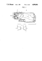
- FIG. 1 is a sectional view of a gas turbine combustor according to an embodiment of the present invention
- FIG. 2 is a partial enlarged sectional view of a detail of the combustor of FIG. 1;
- FIG. 3 is a sectional view taken along a line III--III in FIG. 2;
- FIG. 4 is a perspective view of a head combustion chamber according to another embodiment of the present invention.
- FIG. 5 is a partially sectional perspective view of the second stage fuel supply portion of the gas turbine combustor shown in FIG. 1;
- FIGS. 6 and 7 each are schematic views illustrating a flow pattern of the air and fuel in the head portion of the combustion chamber
- FIG. 8 is a graphical illustration showing flame stability depending upon the protruding length of the fuel nozzle
- FIG. 9 is graphical illustration showing a relationship between NOx and CO concentrations and the fuel nozzle protruding length
- FIG. 10 is a graphical illustration showing a relationship between the flow speed for blow out and LA/LC.
- FIG. 11 is a graphical illustration showing a relationship between the NOx concentration and LB/LF
- FIG. 12 is a graphical illustration showing an excess air ratio at various positions in the head combustor
- FIG. 13 is a schematic partial view of a head combustion chamber according to another embodiment of the present invention.
- FIGS. 14a and 14b each are a modification of the head combustion chamber shown in FIG. 13;
- FIG. 15 is a graphical illustration showing relationships of NOx concentration to turbine load
- FIG. 16 is a schematic view for explaining the formation of a combustion flame
- FIG. 17 is a schematic detail view of the fuel supply portion
- FIG. 18 is a schematic detail view of the fuel supply portion according to another embodiment of the invention.
- FIG. 19 is a cross-sectional view showing the fuel supply portion of the second stage according to another of the invention.
- FIGS. 20 and 21 are diagrams showing the direction of supplying fuel in the second stage and interfering condition of the flames
- FIG. 22 is a schematic view of characteristics showing a relationship between the length of the head combustion chamber and the effect for reducing NOx;
- FIG. 23 is a graphical illustration of characteristics showing a relationship between the gas turbine load and the NOx conentration.
- FIG. 24 is a graphical illustration of characteristics showing temperature distribution of flames.
- gas turbine includes compressor 1, a turbine 2, and a combustor generally designated by the reference numeral 3 which is made of an inner casing including an inner a cylinder generally designated by the reference numeral 4, an outer casing including a cylinder 5 and a tail cylinder 8 for introducing a combustion gas 7 to the stator blades 6 of the turbine.
- An end cover 10 is mounted on a side end of the outer cylinder 5 to accommodate a fuel nozzle body 9 of first stage.
- the combustor is 3 further includes an ignition plug 100 and a flame detector that senses the flame (not shown).
- the inner cylinder 4 is divided into a head combustion chamber 11 and a rear combustion chamber 12 having a diameter larger than that of the head combustion chamber 11.
- a hollow frustoconical tube or cone 13 is inserted concentrically in the head combustion chamber 11, with the cone 13 being narrowed from the upstream side toward the downstream side thereby forming an annular space 25 which gradually increases in sectional area from the upstream side to the downstream side, and having front end with fine air openings.
- An air stream 14 compressed by the compressor 1 passes through a diffuser 15, is routed around the tail cylinder 8, and is introduced into the combustion chambers via louvers 151 and lean air holes 16 formed in the inner cylinder 4, via air holes 18 for burning fuel 17 of a second stage, via air holes 19 for combustion formed in the head combustion chamber 11, and via louvers 20.
- the cone 13 has inlet holes 23 for introducing the air, as well as a plurality of cooling-air holes 24 that are annularly arranged in each of a plurality of rows so that the air will flow along the surface of the cone 13.
- the plurality of fuel nozzles 22 are arranged annularly and penetrate through the end wall 21, with annular spaces for air passages formed between the end wall holes 28 and the nozzle surfaces.
- the fuel injection holes 221 of the nozzles 22 are located upstream of head combustion chamber 11 and open nearly at right-angles to the axis of the inner cylinder 4.
- the fuel 27 jetted therefrom is mixed with the air introduced through the air holes 19a, 19b, 19c and 19d formed in the wall of the head combustion chamber 11, so that combustion is sustained.
- the fuel nozzles 22 are located close to the side wall of the head combustion chamber 11.
- the fuel is quickly mixed with the air introduced through the air holes 19a, 19b, 19c, 19d, and with the air stream from the air holes 28, making it possible to increase the cooling effect of the air at the initial stage of combustion. Therefore, development of hot spots can be suppressed and the formation of NOx can be reduced.
- a plurality of fuel injection holes 221 are provided at positions close to the side wall of the head combustion chamber 11, in order to promote the above-mentioned mixing effects, as well as to disperse the flame or to establish a so-called divisional combustion. Owing to these synergistic effects, formation of NOx can be reduced greatly.
- the provision of the cone 13 further limits the formation of NOx, so that the cooling effect and the mixing effect are not lost.
- the air through the air holes 19a, 19b, 19c, 19d formed in the side wall of the head combustion chamber 11 is not allowed to reach the central portion because there is the cone 13 there. Furtheremore, the formation of NOx can be greatly limited since the flame is effectively cooled by the cone 13 and is cooled from the inner side by the cooling air 20b that is ejected from a plurality of fine holes 24 formed annularly in the surface of the cone 13.
- the fuel nozzles 22 facilitate mixing the fuel with the air introduced upstream from the fuel injection holes 221 depending upon the length by which they protrude into the combustor 3, and are a crucial factor in limiting the formation of NOx. Good mixing is obtained if the fuel injection holes 221 are near the air holes 19a, and formation of NOx is strictly limited.
- the fuel injection holes 221 of the fuel nozzles 22 are positoned near the air holes 19a annularly arranged and form a first air hole row.
- long fuel nozzles 22a and short fuel nozzles 22b are arranged alternatingly to change the positions for injecting the fuel into the combustion chamber 3, for instance.
- the fuel nozzle 22a inject the fuel downstream from the group of air holes 19a, and the fuel nozzle 22b inject the fuel upstream therefrom.
- Air and fuel supply means for the second stage is provided on the inner 4 on the upstream side end of the rear combustor chamber 12 for second combustion stage.
- the air and fuel supply means consists of air inlets formed by a plurality of whirling vanes 37, and fuel nozzles, 34 each disposed between the vanes 37.
- the fuel nozzles 34 are mounted on a nozzle flange in which passages for fuel 17 are formed for supplying fuel into each fuel nozzles 34.
- the nozzle 34 has fuel injection holes 35 at a tip thereof.
- FIGS. 6 and 7 illustrate flow patterns of the air and fuel near the head portion of the combustion chamber 11, wherein solid lines indicate the flow of air, and the chain lines indicate the flow condition of fuel.
- the vortex flow includes upward flows and downward flows and is further reinforced by the reverse flow components produced by the air jet from the outer wall of the inner cylinder 4.
- the fuel is taken in large amounts by the vortex region A and the fuel concentration increases.
- the fuel is injected at a position behind the air jet (La ⁇ Lf) that flows via the air holes 19a formed in the outer wall of the inner cylinder 4 as shown in FIG. 7, the fuel flows in very small amounts into the vortex region A that is formed upstream from the fuel nozzles. It is evident that the difference in the fuel concentration in the vortex flow region seriously affects the flame-stabilizing performance and combustion characteristics.
- FIGS. 8 and 9 illustrate experimental results related to flame stability and combustion characteristics determined by the length Lf of fuel nozzles 22 from the end wall 21 to the fuel injection hole 221.
- the stability of flame increases with the decrease in the length Lf of the fuel nozzles however, Nox, is formed in increasing amounts. If the fuel nozzles 22a, 22b are lengthened, Nox is formed in reduced amounts, but uncombusted gases such as carbon monoxide and the like increase and the flame stability decreases.
- the plurality of air holes 28 are formed in the end wall 21 at the head portion of the combustion chamber to surround the fuel nozzle 22.
- the air may be introduced from positions inside or outside of the combustion chamber to sufficiently accomplish the object, provided it does not interrupt the vortex flow region but rather reinforces it.
- the position of air holes of the first stage serves as a factor that controls the dimensions and intensity of the vortex flow region, and greatly affects the stability of flame.
- FIG. 10 shows flame blow-out characteristics when the position of injecting fuel is maintained constant in relation to a ratio of a distance La between the side wall 21 and the first air hole row, to the width Lc of the annular combustion chamber at the end wall 21.
- the adaptable range of ratio La/Le is smaller than 0.6, the vortex flow region that contributes to stabilizing the flame decreases, and the combustion becomes less stable due to the lean mixture that results from the surrounding flow of air and due to the decrease in the combustion temperature.
- the ratio La/Lc is smaller than 0.5, it is difficult to ignite the mixture.
- the ratio La/Lc is greater than 1.7, the vortex flow region increases noticeably.
- the flame stabilizing mechanism of this embodiment in particular, the flame is generated near the fuel injection holes of the fuel injection nozzles, and combustion is sustained by the combustion product (high-temperature gas) that flows from downstream to upstream due to the surrounding air flow, and the flame is thereby stabilized.
- the cone 13 installed at the central portion of the inner cylinder 4 and the protruding length Lf of the fuel nozzles 22.
- a high-temperature combustion portion is less likely to form at the center of the combustion chamber than when the cone 13 is not used. Since an annular combustion space or chamber 25 is formed, this facilitates both dispersed fuel injection and mixed fuel with air introduced from the wall surface of the inner cylinder 4. Relatively lean combustion is thereby sustained so that a high-temperature portion does not develop. Therefore, less intense combustion can be accomplished which is less likely to form Nox.
- FIG. 11 shows the relationship between the concentration of NOx and the ratio of the length Lb of the cone to the protruding length Lf of the fuel nozzles 22.
- the length Lb of the cone 13 increases, Nox is formed in reduced amounts.
- the amount of air introduced decreases at the head combustion chamber 11.
- the cooling function decreases on the wall of the head combustion chamber 11 and on the wall of the cone 13, and the temperature of the metal rises thereby reducing reliability. If the length Lb of the cone 13 is reduced, fuel and air are not well mixed.
- FIG. 12 specifically shows the condition of air flow near the head portion of combustion chamber.
- the air is introduced in such amounts so as to fall within combustible ranges at all times when the gas turbine is in operation, i.e., under light load or heavy load.
- air is introduced at a ratio of 8% to 20% through the air holes 28 formed in the end wall 21 at the head portion, air is introduced at a rate of 10% to 23% through the air holes 19a of the first row, and at a rate of 57% to 82% with respect to the amount of air for combustion in the head combustion chamber through the holes (19b to 19d) of the second to fourth row formed downstream.
- short fuel nozzles 22 (22b) for stabilizing the flame protrude up in the vicinity of the air holes 19a for first stage combustion The fuel nozzle 22 (22a) for combustion have a length 1.5 times the position of the air holes 19a.
- the fuel nozzles 22b for stabilizing the combustion and the fuel nozzles 22a for combustion are alternatingly arranged annularly maintaining a pitch which is nearly equal to the protruding length of the fuel nozzle 22b for stabilizing the fuel.
- the fuel nozzles 22 inject the fuel in a direction nearly perpendicularly to the longitudinal axis of the combustion chamber.
- the flame of flame-stabilizing portion and the flame for combustion take place being separated axially and annularly in the combustion chamber. Therefore, since the flames are dispersed, combustion is sustained over a low uniform temperature range so as to form relatively little NOx.
- distance between fuel nozzles may be shortened both in axial and annular directions to provide more fuel nozzles. This, however, is limited by the size and shape of the combustor. Further, high-temperature regions are formed by the mutual interference of the flames.
- FIG. 13 illustrates another embodiment of the construction of a fuel nozzle.
- the nozzle 22c has fuel injection holes 22d and 22e for stabilizing the flame and for combustion.
- FIGS. 14a and 14b illustrate a further embodiment of a fuel nozzle.
- the fuel nozzles 22f, 22g and 22h, 22i protrude from the side of the inner cylinder 11 and from the side of the cone 13, respectively.
- the relationship between the length of the head combustion chamber and the fuel supply position of the second stage produces a function as described below inclusive of the cone 13 located in the head combustion chamber 11. That is, in the annular space 25 in the head combustion chamber 11, it is essential that the first stage fuel is nearly completely combusted. Even when the second stage fuel and air are supplied and combusted, flow in the head combustion chamber 11 of the first stage should be held to a minimum.
- the head combustion chamber 11 should be so determined that the fuel of the first stage is mixed with the air introduced through the holes 19a to 19d and is burned almost completely in the annular space 25 defined by the inner wall of the head combustion chamber and the outer wall of the cone 13.
- FIG. 16 shows the relationship between the positions of the fuel and air supply means in the second stage and the NOx concentration.
- increase in the length of the head combustion chamber 11 causes the cooling area of the wall of the head combustion chamber to increase and, hence, permits the cooling air to flow in increased amounts.
- cooling air is introduced between the flame of the first stage and the fuel gas of the second stage when the fuel gas is to be introduced from the second stage. This adversely affects ignition from the first stage to the fuel gas of the second stage. For this reason, the length of the head combustion chamber 11 is not increased by more than a predetermined value.
- the length of the head combustion chamber 11 should typically be from about 1.2 to about 2.0 as great as the outer diameter of the head combustion chamber 11, and should ideally be about 1.5 times that of the outer diameter of the head combustion chamber 11, though it may vary depending upon the diameter and length of the cone 13.
- Length of the cone 13 determine the volume of the head combustion chamber 11. Fundamentally, however, with the cone 13 being longer than the head combustion chamber 11, combustion gas expands in the rear combustion chamber 12 when combustion of the second stage is initiated, and the pressure loss (resistance) increases at the outlet portion of the head combustion chamber 11 due to the acceleration of combustion gas.
- the inner cylindrical cone 13 should have such a length that limits the effect of gas acceleration loss caused by combustion in the second stage.
- the cone 13 should be shorter than the head combustion chamber 11, and should have a volume sufficient to withstand a sudden expansion of combustion gas even when the combustion gas is accelerated from the tip of the cone to the outlet of the head combustion chamber.
- the ratio Lb/L is small or if the cone 13 is short, the flame of first stage combustion is formed on the portion of axis at the front end of the cone 13. Therefore, a high-temperature portion is formed in the portion of axis, and NOx is formed in large amounts.
- the ratio Lb/L approaches 1, furthermore, NOx is generated in large amounts as described above, and the temperature rises in the wall of the head portion. Accordingly, the cone 13 should be shorter than the head combustion chamber 11.
- the area of air openings relative to the head combustion chamber should be 50 to 55% of the total opening areas
- the area of air openings relative to the second stage should be 20 to 30%
- the air flow areas open to the rear combustion chamber should be 20 to 30%
- the cooling areas open to the cone 13 should be 7 to 10%.
- the cone 13 is provided with air openings for combustion in addition to the openings for introducing cooling air, combustion is promoted by the air stream, and hot spots are formed. Therefore, the cone 13 should be provided only with the holes for cooling air. If the area of air holes relative to the second stage becomes greater than 30%, ignition is adversely affected.
- FIG. 17 shows enlargement of the fuel nozzles 34 and the whirling vanes 37.
- the whirling vanes 37 are disposed in parallel to each other and inclined to the axis of the inner cylinder 4 to whirl the air.
- the nozzles 34 have at the tips injection holes 34 perforated in the radial and peripheral directions with respect to the inner casing 4.
- the tip portion is disposed in the air hole 33 at the central portion with respect to the cross-section of the air hole so that fuel injected through the hole 35 is well mixed with air.
- FIG. 18 illustrates a modification of the whirling vane 37.
- the vane 37 has a bent portion (41a, 41b, 41c) which is parallel to the axis of the nozzle 34.
- FIG. 19 shows another embodiment of the fuel and air supply means according to the present invention.
- the whirling vanes 37 are secured to both a supporting member 38 which is joined to the nozzle flange 39, and a guide plate 43b.
- the supporting member 38 and guide plate 43b are inserted between the head combustion and the rear combustion chamber 12 via resilient sealing members 42a and 42b so that the whirling vane 37 will be free from displacement of the inner cylinder 4 due to the thermal expansion.
- the nozzle 34 secured to the nozzle flange 39 axially extends into the air hole defined by the vanes 37.
- Air for second stage combustion is introduced into the rear combustion chamber 12 through a guide portion formed by a guide member 43a supported by the supporting member 38 and a guide portion 43b of the guide plate, whereby the air is introduced smooth into the combustion chamber without producing eddy and without staying.
- the fuel 17 is introdced into a fuel reservoir 31 via a path 30 as shown in FIG. 19.
- the fuel nozzles 34 supply the fuel to the vicinity of air inlets or holes 33 that are open in the air path 32 of the second stage and in the rear combustion chamber 12. That is, the fuel of the second stage is supplied from the fuel reservoir 31 and is injected through fuel injection holes 35 along with the air stream through the air holes 33.
- the air stream 36 of the second stage is supplied into the main combustion chamber in the form of a whirling stream 36' (shown in FIG. 5) so that combustion time is extended as long as possible.
- the lean mixture is then supplied into the main combustion chamber where the gas is ignited by the flame of the head combustion chamber, and low-temperature lean combustion is established to decrease the formation of NOx.
- the key point to reduce the formation of NOx in the second stage is how to thoroughly mix air and fuel.
- the best method for this purpose is to extend the mixing time.
- the whirling vanes 37 are provided to lengthen the air paths, and the fuel is supplied into the whirling streams flowing therethrough.
- the important point is that the flame not be introduced into the air paths of the second stage and, particularly, that the flame not be introduced into the vanes 37.
- the air paths surrounded by the vanes 37 establish conditions that insure adequate combustion.
- the ejecting speed of a mixture of the air and fuel through the vanes 37 is about 100 meters/second, whereas, the propagation speeed of flame in a turbulent flow is 5 meters/second at the fastest. Under ideal conditions, therefore, backfire does not occur.
- the fuel 17 is injected from the injection holes 35 into the air paths surrounded by the whirling vanes 37.
- the injection holes are between the whirling vanes.
- the upstream side of the whirling vanes 37 is curved as designated at 41a, 41b, 41c, as shown in FIG. 18, so as to be in alignment with the axis of the fuel nozzles 34, such that the fuel and the air are mixed together more desirably.
- the structure shown in FIG. 19 maintains a homogeneous mixture of the air and fuel for long of time. Further, concentration of fuel is not diverted in the air path, and local hot spots are not formed. Moreover, smooth flow of air by the curved portions 43a, 43b effects homogeneous mixing of the air and fuel. No eddy current or stagnation develops, nor any backfire.
- Described below is the formation of NOx that is affected by the interference of flame in the first and flame in the second stage and the air stream are introduced nearly at right angles (or it may be a swirling current) with the flame 45 of head portion from the rear portion 44 of the head combustion chamber, the flame 45 of head portion interferes as designated at 47 with the rear flame 46, thereby causing hot spots where the combustion temperature is high forming NOx in large amounts.
- FIG. 21 therefore, it is essential to divide the flame so that the flame 45 of head portion is not interfere with the flame 46 of rear portion, and that NOx is formed only in small amounts. Therefore, it can be contrived to direct the flame of the second stage toward a direction indicated by a dotted line 48. In this case, however, the fuel injected into the second stage is not ignited so quickly by the flame 45 of head portion. Therefore, the flame in the second stage cannot be outwardly directed excessively.
- FIG. 22 shows in comparison the NOx concentrations, by ratio (NOx ⁇ 2 /NOx ⁇ 1 ) of NOx in second stage to NOx in first stage, when the flame is directed in a horizontal direction as indicated by a curve A and when the flame is directed at right angles thereto as indicated by a curve B. Interference with the flame is reduced, and NOx is formed in reduced amounts when the flame is introduced in a horizontal direction rather than in a direction at right angles thereto.
- a plurality of fuel nozzles are provided in the first stage and in the second stage, and the fuel is supplied from the outer circumferential portion of the combustor liners, in order to disperse the fuel and to homogeneously mix the air and fuel together. Therefore, combustion is effectively sustained under low-temperature and excess-air conditions, making it possible to greatly limit the formation of NOx. That is, as shown in FIG. 23, formation of NOx can be greatly limited in the first stage. Furthermore, with the second stage being combined as indicated by a line B, much less NOx is formed compared with the conventional combustors indicated by a line A.
- FIG. 24 illustrates how the combustion condition in the first stage affects the combustion condition in the second stage.
- FIG. 24 shows the distribution of gas temperature at the outlet portion of the head combustion chamber.
- the conventional combustors in which a single fuel nozzle is located on the axis, the temperature rises at the axis in the combustion chamber.
- the fuel is well distributed, and the air and the fuel are homogeneously mixed. Therefore, the high-temperature portion that was seen in the prior art is not present.
- high-temperature portion that was seen in the prior art is not present therefore, high-temperature portions are likely to exist along the periphery.
- the cone 13 is installed in the portion of axis, and cooling air is supplied. Therefore, no high-temperature portion develops along the axis. Namely, Nox is formed in greatly reduced amounts by first stage combustion.
- the temperature rise along the periphery facilitates combustion, making it possible to reduce the formation of uncombusted components such as carbon monoxide (CO), uncombusted products (HC) and the like.
- FIG. 15 shows the results of combustion tests using the combustor of the construction of the present invention.
- the combustion system of the present invention helps reduce the formation of NOx by 30% during the rated operation of a gas turbine.
- the flame stability furthermore, it was confirmed that the combustion could be stably sustained over the operating range of the gas turbine.
Landscapes
- Engineering & Computer Science (AREA)
- Chemical & Material Sciences (AREA)
- Combustion & Propulsion (AREA)
- Mechanical Engineering (AREA)
- General Engineering & Computer Science (AREA)
Applications Claiming Priority (4)
| Application Number | Priority Date | Filing Date | Title |
|---|---|---|---|
| JP14385184A JPS6122106A (ja) | 1984-07-10 | 1984-07-10 | ガスタ−ビン燃焼器 |
| JP14385284A JPS6122127A (ja) | 1984-07-10 | 1984-07-10 | ガスタ−ビン燃焼器 |
| JP59-143851 | 1984-10-07 | ||
| JP59-143852 | 1984-10-07 |
Related Parent Applications (1)
| Application Number | Title | Priority Date | Filing Date |
|---|---|---|---|
| US06752680 Continuation | 1985-07-08 |
Publications (1)
| Publication Number | Publication Date |
|---|---|
| US4898001A true US4898001A (en) | 1990-02-06 |
Family
ID=26475467
Family Applications (1)
| Application Number | Title | Priority Date | Filing Date |
|---|---|---|---|
| US07/144,646 Expired - Lifetime US4898001A (en) | 1984-07-10 | 1988-01-11 | Gas turbine combustor |
Country Status (3)
| Country | Link |
|---|---|
| US (1) | US4898001A (fr) |
| EP (1) | EP0169431B1 (fr) |
| CA (1) | CA1258379A (fr) |
Cited By (117)
| Publication number | Priority date | Publication date | Assignee | Title |
|---|---|---|---|---|
| US5101633A (en) * | 1989-04-20 | 1992-04-07 | Asea Brown Boveri Limited | Burner arrangement including coaxial swirler with extended vane portions |
| US5127229A (en) * | 1988-08-08 | 1992-07-07 | Hitachi, Ltd. | Gas turbine combustor |
| US5239831A (en) * | 1990-08-20 | 1993-08-31 | Hitachi, Ltd. | Burner having one or more eddy generating devices |
| US5323614A (en) * | 1992-01-13 | 1994-06-28 | Hitachi, Ltd. | Combustor for gas turbine |
| EP0616170A1 (fr) * | 1993-03-18 | 1994-09-21 | Hitachi, Ltd. | Dispositif et procédé pour mélanger du combustible gazeux et de l'air de combustion |
| US5377483A (en) * | 1993-07-07 | 1995-01-03 | Mowill; R. Jan | Process for single stage premixed constant fuel/air ratio combustion |
| US5415000A (en) * | 1994-06-13 | 1995-05-16 | Westinghouse Electric Corporation | Low NOx combustor retro-fit system for gas turbines |
| US5450724A (en) * | 1993-08-27 | 1995-09-19 | Northern Research & Engineering Corporation | Gas turbine apparatus including fuel and air mixer |
| US5572862A (en) * | 1993-07-07 | 1996-11-12 | Mowill Rolf Jan | Convectively cooled, single stage, fully premixed fuel/air combustor for gas turbine engine modules |
| US5613357A (en) * | 1993-07-07 | 1997-03-25 | Mowill; R. Jan | Star-shaped single stage low emission combustor system |
| US5628182A (en) * | 1993-07-07 | 1997-05-13 | Mowill; R. Jan | Star combustor with dilution ports in can portions |
| US5638674A (en) * | 1993-07-07 | 1997-06-17 | Mowill; R. Jan | Convectively cooled, single stage, fully premixed controllable fuel/air combustor with tangential admission |
| EP0711957A3 (fr) * | 1994-10-14 | 1997-07-30 | Ulstein Turbine As | Dispositif de mélange carburant-air |
| EP0805308A1 (fr) * | 1996-05-02 | 1997-11-05 | General Electric Company | Chambre de combustion à prémélange avec injection directe maigre et faible émission de NOx |
| US5761906A (en) * | 1995-01-13 | 1998-06-09 | European Gas Turbines Limited | Fuel injector swirler arrangement having a shield means for creating fuel rich pockets in gas-or liquid-fuelled turbine |
| US5794449A (en) * | 1995-06-05 | 1998-08-18 | Allison Engine Company, Inc. | Dry low emission combustor for gas turbine engines |
| EP0863369A2 (fr) | 1997-03-07 | 1998-09-09 | R. Jan Mowill | Chambre de combustion à étage unique avec prémélange |
| GB2328011A (en) * | 1997-08-05 | 1999-02-10 | Europ Gas Turbines Ltd | Combustor for gas or liquid fuelled turbine |
| US5901555A (en) * | 1996-02-05 | 1999-05-11 | Mitsubishi Heavy Industries, Ltd. | Gas turbine combustor having multiple burner groups and independently operable pilot fuel injection systems |
| US5924276A (en) * | 1996-07-17 | 1999-07-20 | Mowill; R. Jan | Premixer with dilution air bypass valve assembly |
| US6094916A (en) * | 1995-06-05 | 2000-08-01 | Allison Engine Company | Dry low oxides of nitrogen lean premix module for industrial gas turbine engines |
| WO2001040713A1 (fr) | 1999-12-03 | 2001-06-07 | Mowill Rolf Jan | Buse d'evacuation a premelangeur refroidie pour bruleur de turbine a gaz, et son procede de fonctionnement |
| US6374615B1 (en) | 2000-01-28 | 2002-04-23 | Alliedsignal, Inc | Low cost, low emissions natural gas combustor |
| US6564555B2 (en) | 2001-05-24 | 2003-05-20 | Allison Advanced Development Company | Apparatus for forming a combustion mixture in a gas turbine engine |
| EP1319896A2 (fr) | 2001-12-14 | 2003-06-18 | R. Jan Mowill | Dispositif de prémélange carburant / air avec géométrie variable et méthode de contrôle de vitesse de sortie |
| US6761033B2 (en) * | 2002-07-18 | 2004-07-13 | Hitachi, Ltd. | Gas turbine combustor with fuel-air pre-mixer and pre-mixing method for low NOx combustion |
| US20040255422A1 (en) * | 2003-06-18 | 2004-12-23 | Reback Scott Mitchell | Methods and apparatus for injecting cleaning fluids into combustors |
| US6871503B1 (en) * | 1999-10-20 | 2005-03-29 | Hitachi, Ltd. | Gas turbine combustor with fuel-air pre-mixer and pre-mixing method for low nox combustion |
| US6925809B2 (en) | 1999-02-26 | 2005-08-09 | R. Jan Mowill | Gas turbine engine fuel/air premixers with variable geometry exit and method for controlling exit velocities |
| US20060272332A1 (en) * | 2005-06-03 | 2006-12-07 | Siemens Westinghouse Power Corporation | System for introducing fuel to a fluid flow upstream of a combustion area |
| US20100212325A1 (en) * | 2009-02-23 | 2010-08-26 | Williams International, Co., L.L.C. | Combustion system |
| US20110000671A1 (en) * | 2008-03-28 | 2011-01-06 | Frank Hershkowitz | Low Emission Power Generation and Hydrocarbon Recovery Systems and Methods |
| US20120079827A1 (en) * | 2008-02-20 | 2012-04-05 | Flexenergy Energy Systems, Inc. | Air-cooled swirlerhead |
| US20120208141A1 (en) * | 2011-02-14 | 2012-08-16 | General Electric Company | Combustor |
| US20120227407A1 (en) * | 2009-12-15 | 2012-09-13 | Man Diesel & Turbo Se | Burner for a turbine |
| JP2013140007A (ja) * | 2012-01-04 | 2013-07-18 | General Electric Co <Ge> | ターボ機械構成要素の流れスリーブ |
| US20130180261A1 (en) * | 2012-01-13 | 2013-07-18 | General Electric Company | Combustor and method for reducing thermal stresses in a combustor |
| CN103925617A (zh) * | 2013-01-14 | 2014-07-16 | 通用电气公司 | 涡轮机械构件的流套 |
| US8893500B2 (en) | 2011-05-18 | 2014-11-25 | Solar Turbines Inc. | Lean direct fuel injector |
| US8919132B2 (en) | 2011-05-18 | 2014-12-30 | Solar Turbines Inc. | Method of operating a gas turbine engine |
| US20150075171A1 (en) * | 2012-03-29 | 2015-03-19 | Alexander Nikolay Sokolov | Turbomachine combustor assembly |
| US8984857B2 (en) | 2008-03-28 | 2015-03-24 | Exxonmobil Upstream Research Company | Low emission power generation and hydrocarbon recovery systems and methods |
| US20150107255A1 (en) * | 2013-10-18 | 2015-04-23 | General Electric Company | Turbomachine combustor having an externally fueled late lean injection (lli) system |
| US9027321B2 (en) | 2008-03-28 | 2015-05-12 | Exxonmobil Upstream Research Company | Low emission power generation and hydrocarbon recovery systems and methods |
| US20150159877A1 (en) * | 2013-12-06 | 2015-06-11 | General Electric Company | Late lean injection manifold mixing system |
| US9127843B2 (en) | 2013-03-12 | 2015-09-08 | Pratt & Whitney Canada Corp. | Combustor for gas turbine engine |
| US20150308349A1 (en) * | 2014-04-23 | 2015-10-29 | General Electric Company | Fuel delivery system |
| US9182124B2 (en) | 2011-12-15 | 2015-11-10 | Solar Turbines Incorporated | Gas turbine and fuel injector for the same |
| US9222671B2 (en) | 2008-10-14 | 2015-12-29 | Exxonmobil Upstream Research Company | Methods and systems for controlling the products of combustion |
| US9228747B2 (en) | 2013-03-12 | 2016-01-05 | Pratt & Whitney Canada Corp. | Combustor for gas turbine engine |
| US9353682B2 (en) | 2012-04-12 | 2016-05-31 | General Electric Company | Methods, systems and apparatus relating to combustion turbine power plants with exhaust gas recirculation |
| US9366187B2 (en) | 2013-03-12 | 2016-06-14 | Pratt & Whitney Canada Corp. | Slinger combustor |
| US9463417B2 (en) | 2011-03-22 | 2016-10-11 | Exxonmobil Upstream Research Company | Low emission power generation systems and methods incorporating carbon dioxide separation |
| US9512759B2 (en) | 2013-02-06 | 2016-12-06 | General Electric Company | System and method for catalyst heat utilization for gas turbine with exhaust gas recirculation |
| US9541292B2 (en) | 2013-03-12 | 2017-01-10 | Pratt & Whitney Canada Corp. | Combustor for gas turbine engine |
| US9574496B2 (en) | 2012-12-28 | 2017-02-21 | General Electric Company | System and method for a turbine combustor |
| US9581081B2 (en) | 2013-01-13 | 2017-02-28 | General Electric Company | System and method for protecting components in a gas turbine engine with exhaust gas recirculation |
| US9587510B2 (en) | 2013-07-30 | 2017-03-07 | General Electric Company | System and method for a gas turbine engine sensor |
| US9599021B2 (en) | 2011-03-22 | 2017-03-21 | Exxonmobil Upstream Research Company | Systems and methods for controlling stoichiometric combustion in low emission turbine systems |
| US9599070B2 (en) | 2012-11-02 | 2017-03-21 | General Electric Company | System and method for oxidant compression in a stoichiometric exhaust gas recirculation gas turbine system |
| US20170082291A1 (en) * | 2014-05-30 | 2017-03-23 | Kawasaki Jukogyo Kabushiki Kaisha | Combustor for gas turbine engine |
| US9611756B2 (en) | 2012-11-02 | 2017-04-04 | General Electric Company | System and method for protecting components in a gas turbine engine with exhaust gas recirculation |
| US9617914B2 (en) | 2013-06-28 | 2017-04-11 | General Electric Company | Systems and methods for monitoring gas turbine systems having exhaust gas recirculation |
| US9618261B2 (en) | 2013-03-08 | 2017-04-11 | Exxonmobil Upstream Research Company | Power generation and LNG production |
| US9631542B2 (en) | 2013-06-28 | 2017-04-25 | General Electric Company | System and method for exhausting combustion gases from gas turbine engines |
| US9631815B2 (en) | 2012-12-28 | 2017-04-25 | General Electric Company | System and method for a turbine combustor |
| US9670841B2 (en) | 2011-03-22 | 2017-06-06 | Exxonmobil Upstream Research Company | Methods of varying low emission turbine gas recycle circuits and systems and apparatus related thereto |
| US9689309B2 (en) | 2011-03-22 | 2017-06-27 | Exxonmobil Upstream Research Company | Systems and methods for carbon dioxide capture in low emission combined turbine systems |
| US9708977B2 (en) | 2012-12-28 | 2017-07-18 | General Electric Company | System and method for reheat in gas turbine with exhaust gas recirculation |
| US9732675B2 (en) | 2010-07-02 | 2017-08-15 | Exxonmobil Upstream Research Company | Low emission power generation systems and methods |
| US9732673B2 (en) | 2010-07-02 | 2017-08-15 | Exxonmobil Upstream Research Company | Stoichiometric combustion with exhaust gas recirculation and direct contact cooler |
| US9752458B2 (en) | 2013-12-04 | 2017-09-05 | General Electric Company | System and method for a gas turbine engine |
| US9784182B2 (en) | 2013-03-08 | 2017-10-10 | Exxonmobil Upstream Research Company | Power generation and methane recovery from methane hydrates |
| US9784140B2 (en) | 2013-03-08 | 2017-10-10 | Exxonmobil Upstream Research Company | Processing exhaust for use in enhanced oil recovery |
| US9784185B2 (en) | 2012-04-26 | 2017-10-10 | General Electric Company | System and method for cooling a gas turbine with an exhaust gas provided by the gas turbine |
| US9803865B2 (en) | 2012-12-28 | 2017-10-31 | General Electric Company | System and method for a turbine combustor |
| US9810050B2 (en) | 2011-12-20 | 2017-11-07 | Exxonmobil Upstream Research Company | Enhanced coal-bed methane production |
| US9819292B2 (en) | 2014-12-31 | 2017-11-14 | General Electric Company | Systems and methods to respond to grid overfrequency events for a stoichiometric exhaust recirculation gas turbine |
| US9835089B2 (en) | 2013-06-28 | 2017-12-05 | General Electric Company | System and method for a fuel nozzle |
| US9863267B2 (en) | 2014-01-21 | 2018-01-09 | General Electric Company | System and method of control for a gas turbine engine |
| US9869279B2 (en) | 2012-11-02 | 2018-01-16 | General Electric Company | System and method for a multi-wall turbine combustor |
| US9869247B2 (en) | 2014-12-31 | 2018-01-16 | General Electric Company | Systems and methods of estimating a combustion equivalence ratio in a gas turbine with exhaust gas recirculation |
| US9885290B2 (en) | 2014-06-30 | 2018-02-06 | General Electric Company | Erosion suppression system and method in an exhaust gas recirculation gas turbine system |
| US9903271B2 (en) | 2010-07-02 | 2018-02-27 | Exxonmobil Upstream Research Company | Low emission triple-cycle power generation and CO2 separation systems and methods |
| US9903588B2 (en) | 2013-07-30 | 2018-02-27 | General Electric Company | System and method for barrier in passage of combustor of gas turbine engine with exhaust gas recirculation |
| US9903316B2 (en) | 2010-07-02 | 2018-02-27 | Exxonmobil Upstream Research Company | Stoichiometric combustion of enriched air with exhaust gas recirculation |
| US9915200B2 (en) | 2014-01-21 | 2018-03-13 | General Electric Company | System and method for controlling the combustion process in a gas turbine operating with exhaust gas recirculation |
| US9932874B2 (en) | 2013-02-21 | 2018-04-03 | Exxonmobil Upstream Research Company | Reducing oxygen in a gas turbine exhaust |
| US9938861B2 (en) | 2013-02-21 | 2018-04-10 | Exxonmobil Upstream Research Company | Fuel combusting method |
| US9951658B2 (en) | 2013-07-31 | 2018-04-24 | General Electric Company | System and method for an oxidant heating system |
| US9958161B2 (en) | 2013-03-12 | 2018-05-01 | Pratt & Whitney Canada Corp. | Combustor for gas turbine engine |
| US10012151B2 (en) | 2013-06-28 | 2018-07-03 | General Electric Company | Systems and methods for controlling exhaust gas flow in exhaust gas recirculation gas turbine systems |
| US10030588B2 (en) | 2013-12-04 | 2018-07-24 | General Electric Company | Gas turbine combustor diagnostic system and method |
| US10047633B2 (en) | 2014-05-16 | 2018-08-14 | General Electric Company | Bearing housing |
| US10060359B2 (en) | 2014-06-30 | 2018-08-28 | General Electric Company | Method and system for combustion control for gas turbine system with exhaust gas recirculation |
| US10079564B2 (en) | 2014-01-27 | 2018-09-18 | General Electric Company | System and method for a stoichiometric exhaust gas recirculation gas turbine system |
| US10094566B2 (en) | 2015-02-04 | 2018-10-09 | General Electric Company | Systems and methods for high volumetric oxidant flow in gas turbine engine with exhaust gas recirculation |
| US10100741B2 (en) | 2012-11-02 | 2018-10-16 | General Electric Company | System and method for diffusion combustion with oxidant-diluent mixing in a stoichiometric exhaust gas recirculation gas turbine system |
| US10107495B2 (en) | 2012-11-02 | 2018-10-23 | General Electric Company | Gas turbine combustor control system for stoichiometric combustion in the presence of a diluent |
| US10145269B2 (en) | 2015-03-04 | 2018-12-04 | General Electric Company | System and method for cooling discharge flow |
| US10208677B2 (en) | 2012-12-31 | 2019-02-19 | General Electric Company | Gas turbine load control system |
| US10215412B2 (en) | 2012-11-02 | 2019-02-26 | General Electric Company | System and method for load control with diffusion combustion in a stoichiometric exhaust gas recirculation gas turbine system |
| GB2565761A (en) * | 2017-07-28 | 2019-02-27 | Tunley Enginering | Combustion engine fuel mixture system |
| US10221762B2 (en) | 2013-02-28 | 2019-03-05 | General Electric Company | System and method for a turbine combustor |
| US10227920B2 (en) | 2014-01-15 | 2019-03-12 | General Electric Company | Gas turbine oxidant separation system |
| US10253690B2 (en) | 2015-02-04 | 2019-04-09 | General Electric Company | Turbine system with exhaust gas recirculation, separation and extraction |
| US10267270B2 (en) | 2015-02-06 | 2019-04-23 | General Electric Company | Systems and methods for carbon black production with a gas turbine engine having exhaust gas recirculation |
| US10273880B2 (en) | 2012-04-26 | 2019-04-30 | General Electric Company | System and method of recirculating exhaust gas for use in a plurality of flow paths in a gas turbine engine |
| US10315150B2 (en) | 2013-03-08 | 2019-06-11 | Exxonmobil Upstream Research Company | Carbon dioxide recovery |
| US10316746B2 (en) | 2015-02-04 | 2019-06-11 | General Electric Company | Turbine system with exhaust gas recirculation, separation and extraction |
| US10480792B2 (en) | 2015-03-06 | 2019-11-19 | General Electric Company | Fuel staging in a gas turbine engine |
| US10655542B2 (en) | 2014-06-30 | 2020-05-19 | General Electric Company | Method and system for startup of gas turbine system drive trains with exhaust gas recirculation |
| US10788212B2 (en) | 2015-01-12 | 2020-09-29 | General Electric Company | System and method for an oxidant passageway in a gas turbine system with exhaust gas recirculation |
| US11002193B2 (en) * | 2017-12-15 | 2021-05-11 | Delavan Inc. | Fuel injector systems and support structures |
| US20210341147A1 (en) * | 2020-05-01 | 2021-11-04 | Mitsubishi Power, Ltd. | Gas Turbine Combustor |
| CN113883550A (zh) * | 2021-11-09 | 2022-01-04 | 浙江大学 | 一种采用周向切向供油方式的低排放回流燃烧室 |
| US12553385B2 (en) * | 2020-03-30 | 2026-02-17 | Ge Vernova Infrastructure Technology Llc | Compact turbomachine combustor |
Families Citing this family (10)
| Publication number | Priority date | Publication date | Assignee | Title |
|---|---|---|---|---|
| CH672366A5 (fr) * | 1986-12-09 | 1989-11-15 | Bbc Brown Boveri & Cie | |
| JP2528894B2 (ja) * | 1987-09-04 | 1996-08-28 | 株式会社日立製作所 | ガスタ―ビン燃焼器 |
| DE68923413T2 (de) * | 1988-09-07 | 1996-04-04 | Hitachi Ltd | Kraftstoff-Luftvormischvorrichtung für eine Gasturbine. |
| JP2544470B2 (ja) * | 1989-02-03 | 1996-10-16 | 株式会社日立製作所 | ガスタ―ビン燃焼器及びその運転方法 |
| JPH0772616B2 (ja) * | 1989-05-24 | 1995-08-02 | 株式会社日立製作所 | 燃焼器及びその運転方法 |
| JP2758301B2 (ja) * | 1991-11-29 | 1998-05-28 | 株式会社東芝 | ガスタービン燃焼器 |
| GB9410233D0 (en) * | 1994-05-21 | 1994-07-06 | Rolls Royce Plc | A gas turbine engine combustion chamber |
| CN1918432A (zh) * | 2004-02-10 | 2007-02-21 | 株式会社荏原制作所 | 燃烧装置 |
| US7886545B2 (en) * | 2007-04-27 | 2011-02-15 | General Electric Company | Methods and systems to facilitate reducing NOx emissions in combustion systems |
| CN102384473B (zh) * | 2010-08-25 | 2013-07-31 | 中国科学院工程热物理研究所 | 一种燃气轮机无焰驻涡燃烧器 |
Citations (13)
| Publication number | Priority date | Publication date | Assignee | Title |
|---|---|---|---|---|
| GB650608A (en) * | 1948-11-26 | 1951-02-28 | Lucas Ltd Joseph | Improvements relating to internal combustion engine systems |
| US2583416A (en) * | 1948-12-07 | 1952-01-22 | Lucas Ltd Joseph | Liquid fuel vaporizer |
| US2676460A (en) * | 1950-03-23 | 1954-04-27 | United Aircraft Corp | Burner construction of the can-an-nular type having means for distributing airflow to each can |
| US2999359A (en) * | 1956-04-25 | 1961-09-12 | Rolls Royce | Combustion equipment of gas-turbine engines |
| GB894054A (en) * | 1957-10-12 | 1962-04-18 | Maschf Augsburg Nuernberg Ag | Improvements in or relating to combustion chambers for use in gas turbine installations |
| DE2455909A1 (de) * | 1973-11-30 | 1975-06-05 | Rolls Royce 1971 Ltd | Brennkammer fuer gasturbinenstrahltriebwerke |
| US4151713A (en) * | 1977-03-15 | 1979-05-01 | United Technologies Corporation | Burner for gas turbine engine |
| US4292801A (en) * | 1979-07-11 | 1981-10-06 | General Electric Company | Dual stage-dual mode low nox combustor |
| US4344280A (en) * | 1980-01-24 | 1982-08-17 | Hitachi, Ltd. | Combustor of gas turbine |
| GB2097113A (en) * | 1981-04-22 | 1982-10-27 | Gen Electric | Low NOx combustor |
| DE3217674A1 (de) * | 1981-05-12 | 1982-12-02 | Hitachi, Ltd., Tokyo | Combustor fuer eine gasturbine |
| GB2146425A (en) * | 1983-09-08 | 1985-04-17 | Hitachi Ltd | Method of supplying fuel into gas turbine combustor |
| JPS60240833A (ja) * | 1984-05-15 | 1985-11-29 | Hitachi Ltd | ガスタ−ビン燃焼方法及びガスタ−ビン燃焼器 |
-
1985
- 1985-07-08 EP EP85108445A patent/EP0169431B1/fr not_active Expired
- 1985-07-10 CA CA000486578A patent/CA1258379A/fr not_active Expired
-
1988
- 1988-01-11 US US07/144,646 patent/US4898001A/en not_active Expired - Lifetime
Patent Citations (14)
| Publication number | Priority date | Publication date | Assignee | Title |
|---|---|---|---|---|
| GB650608A (en) * | 1948-11-26 | 1951-02-28 | Lucas Ltd Joseph | Improvements relating to internal combustion engine systems |
| US2583416A (en) * | 1948-12-07 | 1952-01-22 | Lucas Ltd Joseph | Liquid fuel vaporizer |
| US2676460A (en) * | 1950-03-23 | 1954-04-27 | United Aircraft Corp | Burner construction of the can-an-nular type having means for distributing airflow to each can |
| US2999359A (en) * | 1956-04-25 | 1961-09-12 | Rolls Royce | Combustion equipment of gas-turbine engines |
| GB894054A (en) * | 1957-10-12 | 1962-04-18 | Maschf Augsburg Nuernberg Ag | Improvements in or relating to combustion chambers for use in gas turbine installations |
| DE2455909A1 (de) * | 1973-11-30 | 1975-06-05 | Rolls Royce 1971 Ltd | Brennkammer fuer gasturbinenstrahltriebwerke |
| US4151713A (en) * | 1977-03-15 | 1979-05-01 | United Technologies Corporation | Burner for gas turbine engine |
| US4292801A (en) * | 1979-07-11 | 1981-10-06 | General Electric Company | Dual stage-dual mode low nox combustor |
| US4344280A (en) * | 1980-01-24 | 1982-08-17 | Hitachi, Ltd. | Combustor of gas turbine |
| GB2097113A (en) * | 1981-04-22 | 1982-10-27 | Gen Electric | Low NOx combustor |
| DE3217674A1 (de) * | 1981-05-12 | 1982-12-02 | Hitachi, Ltd., Tokyo | Combustor fuer eine gasturbine |
| US4598553A (en) * | 1981-05-12 | 1986-07-08 | Hitachi, Ltd. | Combustor for gas turbine |
| GB2146425A (en) * | 1983-09-08 | 1985-04-17 | Hitachi Ltd | Method of supplying fuel into gas turbine combustor |
| JPS60240833A (ja) * | 1984-05-15 | 1985-11-29 | Hitachi Ltd | ガスタ−ビン燃焼方法及びガスタ−ビン燃焼器 |
Cited By (155)
| Publication number | Priority date | Publication date | Assignee | Title |
|---|---|---|---|---|
| US5127229A (en) * | 1988-08-08 | 1992-07-07 | Hitachi, Ltd. | Gas turbine combustor |
| US5101633A (en) * | 1989-04-20 | 1992-04-07 | Asea Brown Boveri Limited | Burner arrangement including coaxial swirler with extended vane portions |
| US5239831A (en) * | 1990-08-20 | 1993-08-31 | Hitachi, Ltd. | Burner having one or more eddy generating devices |
| US5323614A (en) * | 1992-01-13 | 1994-06-28 | Hitachi, Ltd. | Combustor for gas turbine |
| US5515680A (en) * | 1993-03-18 | 1996-05-14 | Hitachi, Ltd. | Apparatus and method for mixing gaseous fuel and air for combustion including injection at a reverse flow bend |
| EP0616170A1 (fr) * | 1993-03-18 | 1994-09-21 | Hitachi, Ltd. | Dispositif et procédé pour mélanger du combustible gazeux et de l'air de combustion |
| US5481866A (en) * | 1993-07-07 | 1996-01-09 | Mowill; R. Jan | Single stage premixed constant fuel/air ratio combustor |
| US5572862A (en) * | 1993-07-07 | 1996-11-12 | Mowill Rolf Jan | Convectively cooled, single stage, fully premixed fuel/air combustor for gas turbine engine modules |
| US5765363A (en) * | 1993-07-07 | 1998-06-16 | Mowill; R. Jan | Convectively cooled, single stage, fully premixed controllable fuel/air combustor with tangential admission |
| US5477671A (en) * | 1993-07-07 | 1995-12-26 | Mowill; R. Jan | Single stage premixed constant fuel/air ratio combustor |
| US6220034B1 (en) | 1993-07-07 | 2001-04-24 | R. Jan Mowill | Convectively cooled, single stage, fully premixed controllable fuel/air combustor |
| EP0635681A1 (fr) | 1993-07-07 | 1995-01-25 | R. Jan Mowill | Chambre de combustion à prémélange d'un rapport constant carburant/comburant et avec combustion dans une seule étappe |
| US5377483A (en) * | 1993-07-07 | 1995-01-03 | Mowill; R. Jan | Process for single stage premixed constant fuel/air ratio combustion |
| US5638674A (en) * | 1993-07-07 | 1997-06-17 | Mowill; R. Jan | Convectively cooled, single stage, fully premixed controllable fuel/air combustor with tangential admission |
| US5628182A (en) * | 1993-07-07 | 1997-05-13 | Mowill; R. Jan | Star combustor with dilution ports in can portions |
| US5613357A (en) * | 1993-07-07 | 1997-03-25 | Mowill; R. Jan | Star-shaped single stage low emission combustor system |
| US5609655A (en) * | 1993-08-27 | 1997-03-11 | Northern Research & Engineering Corp. | Gas turbine apparatus |
| US5564270A (en) * | 1993-08-27 | 1996-10-15 | Northern Research & Engineering Corporation | Gas turbine apparatus |
| US5450724A (en) * | 1993-08-27 | 1995-09-19 | Northern Research & Engineering Corporation | Gas turbine apparatus including fuel and air mixer |
| US5415000A (en) * | 1994-06-13 | 1995-05-16 | Westinghouse Electric Corporation | Low NOx combustor retro-fit system for gas turbines |
| EP0711957A3 (fr) * | 1994-10-14 | 1997-07-30 | Ulstein Turbine As | Dispositif de mélange carburant-air |
| US5761906A (en) * | 1995-01-13 | 1998-06-09 | European Gas Turbines Limited | Fuel injector swirler arrangement having a shield means for creating fuel rich pockets in gas-or liquid-fuelled turbine |
| US5794449A (en) * | 1995-06-05 | 1998-08-18 | Allison Engine Company, Inc. | Dry low emission combustor for gas turbine engines |
| US5813232A (en) * | 1995-06-05 | 1998-09-29 | Allison Engine Company, Inc. | Dry low emission combustor for gas turbine engines |
| US6094916A (en) * | 1995-06-05 | 2000-08-01 | Allison Engine Company | Dry low oxides of nitrogen lean premix module for industrial gas turbine engines |
| US5901555A (en) * | 1996-02-05 | 1999-05-11 | Mitsubishi Heavy Industries, Ltd. | Gas turbine combustor having multiple burner groups and independently operable pilot fuel injection systems |
| US6047550A (en) * | 1996-05-02 | 2000-04-11 | General Electric Co. | Premixing dry low NOx emissions combustor with lean direct injection of gas fuel |
| US6192688B1 (en) | 1996-05-02 | 2001-02-27 | General Electric Co. | Premixing dry low nox emissions combustor with lean direct injection of gas fule |
| EP0805308A1 (fr) * | 1996-05-02 | 1997-11-05 | General Electric Company | Chambre de combustion à prémélange avec injection directe maigre et faible émission de NOx |
| US5924276A (en) * | 1996-07-17 | 1999-07-20 | Mowill; R. Jan | Premixer with dilution air bypass valve assembly |
| EP0863369A2 (fr) | 1997-03-07 | 1998-09-09 | R. Jan Mowill | Chambre de combustion à étage unique avec prémélange |
| GB2328011A (en) * | 1997-08-05 | 1999-02-10 | Europ Gas Turbines Ltd | Combustor for gas or liquid fuelled turbine |
| US6134877A (en) * | 1997-08-05 | 2000-10-24 | European Gas Turbines Limited | Combustor for gas-or liquid-fuelled turbine |
| US6925809B2 (en) | 1999-02-26 | 2005-08-09 | R. Jan Mowill | Gas turbine engine fuel/air premixers with variable geometry exit and method for controlling exit velocities |
| US6871503B1 (en) * | 1999-10-20 | 2005-03-29 | Hitachi, Ltd. | Gas turbine combustor with fuel-air pre-mixer and pre-mixing method for low nox combustion |
| WO2001040713A1 (fr) | 1999-12-03 | 2001-06-07 | Mowill Rolf Jan | Buse d'evacuation a premelangeur refroidie pour bruleur de turbine a gaz, et son procede de fonctionnement |
| US6374615B1 (en) | 2000-01-28 | 2002-04-23 | Alliedsignal, Inc | Low cost, low emissions natural gas combustor |
| US6564555B2 (en) | 2001-05-24 | 2003-05-20 | Allison Advanced Development Company | Apparatus for forming a combustion mixture in a gas turbine engine |
| EP1319896A2 (fr) | 2001-12-14 | 2003-06-18 | R. Jan Mowill | Dispositif de prémélange carburant / air avec géométrie variable et méthode de contrôle de vitesse de sortie |
| US6761033B2 (en) * | 2002-07-18 | 2004-07-13 | Hitachi, Ltd. | Gas turbine combustor with fuel-air pre-mixer and pre-mixing method for low NOx combustion |
| US20040255422A1 (en) * | 2003-06-18 | 2004-12-23 | Reback Scott Mitchell | Methods and apparatus for injecting cleaning fluids into combustors |
| US7065955B2 (en) * | 2003-06-18 | 2006-06-27 | General Electric Company | Methods and apparatus for injecting cleaning fluids into combustors |
| US20060272332A1 (en) * | 2005-06-03 | 2006-12-07 | Siemens Westinghouse Power Corporation | System for introducing fuel to a fluid flow upstream of a combustion area |
| US7810336B2 (en) * | 2005-06-03 | 2010-10-12 | Siemens Energy, Inc. | System for introducing fuel to a fluid flow upstream of a combustion area |
| US20120079827A1 (en) * | 2008-02-20 | 2012-04-05 | Flexenergy Energy Systems, Inc. | Air-cooled swirlerhead |
| US8857739B2 (en) * | 2008-02-20 | 2014-10-14 | Flexenergy Energy Systems, Inc. | Air-cooled swirlerhead |
| US20110000671A1 (en) * | 2008-03-28 | 2011-01-06 | Frank Hershkowitz | Low Emission Power Generation and Hydrocarbon Recovery Systems and Methods |
| US8984857B2 (en) | 2008-03-28 | 2015-03-24 | Exxonmobil Upstream Research Company | Low emission power generation and hydrocarbon recovery systems and methods |
| US8734545B2 (en) | 2008-03-28 | 2014-05-27 | Exxonmobil Upstream Research Company | Low emission power generation and hydrocarbon recovery systems and methods |
| US9027321B2 (en) | 2008-03-28 | 2015-05-12 | Exxonmobil Upstream Research Company | Low emission power generation and hydrocarbon recovery systems and methods |
| US9719682B2 (en) | 2008-10-14 | 2017-08-01 | Exxonmobil Upstream Research Company | Methods and systems for controlling the products of combustion |
| US9222671B2 (en) | 2008-10-14 | 2015-12-29 | Exxonmobil Upstream Research Company | Methods and systems for controlling the products of combustion |
| US10495306B2 (en) | 2008-10-14 | 2019-12-03 | Exxonmobil Upstream Research Company | Methods and systems for controlling the products of combustion |
| US20100212325A1 (en) * | 2009-02-23 | 2010-08-26 | Williams International, Co., L.L.C. | Combustion system |
| US9328924B2 (en) | 2009-02-23 | 2016-05-03 | Williams International Co., Llc | Combustion system |
| US8640464B2 (en) | 2009-02-23 | 2014-02-04 | Williams International Co., L.L.C. | Combustion system |
| US20120227407A1 (en) * | 2009-12-15 | 2012-09-13 | Man Diesel & Turbo Se | Burner for a turbine |
| US9903271B2 (en) | 2010-07-02 | 2018-02-27 | Exxonmobil Upstream Research Company | Low emission triple-cycle power generation and CO2 separation systems and methods |
| US9732673B2 (en) | 2010-07-02 | 2017-08-15 | Exxonmobil Upstream Research Company | Stoichiometric combustion with exhaust gas recirculation and direct contact cooler |
| US9903316B2 (en) | 2010-07-02 | 2018-02-27 | Exxonmobil Upstream Research Company | Stoichiometric combustion of enriched air with exhaust gas recirculation |
| US9732675B2 (en) | 2010-07-02 | 2017-08-15 | Exxonmobil Upstream Research Company | Low emission power generation systems and methods |
| US20120208141A1 (en) * | 2011-02-14 | 2012-08-16 | General Electric Company | Combustor |
| US9689309B2 (en) | 2011-03-22 | 2017-06-27 | Exxonmobil Upstream Research Company | Systems and methods for carbon dioxide capture in low emission combined turbine systems |
| US9599021B2 (en) | 2011-03-22 | 2017-03-21 | Exxonmobil Upstream Research Company | Systems and methods for controlling stoichiometric combustion in low emission turbine systems |
| US9463417B2 (en) | 2011-03-22 | 2016-10-11 | Exxonmobil Upstream Research Company | Low emission power generation systems and methods incorporating carbon dioxide separation |
| US9670841B2 (en) | 2011-03-22 | 2017-06-06 | Exxonmobil Upstream Research Company | Methods of varying low emission turbine gas recycle circuits and systems and apparatus related thereto |
| US8919132B2 (en) | 2011-05-18 | 2014-12-30 | Solar Turbines Inc. | Method of operating a gas turbine engine |
| US8893500B2 (en) | 2011-05-18 | 2014-11-25 | Solar Turbines Inc. | Lean direct fuel injector |
| US9182124B2 (en) | 2011-12-15 | 2015-11-10 | Solar Turbines Incorporated | Gas turbine and fuel injector for the same |
| US9810050B2 (en) | 2011-12-20 | 2017-11-07 | Exxonmobil Upstream Research Company | Enhanced coal-bed methane production |
| EP2613091A3 (fr) * | 2012-01-04 | 2013-08-28 | General Electric Company | Manchon d'écoulement d'un composant de turbomachine |
| JP2013140007A (ja) * | 2012-01-04 | 2013-07-18 | General Electric Co <Ge> | ターボ機械構成要素の流れスリーブ |
| US9140455B2 (en) | 2012-01-04 | 2015-09-22 | General Electric Company | Flowsleeve of a turbomachine component |
| US20130180261A1 (en) * | 2012-01-13 | 2013-07-18 | General Electric Company | Combustor and method for reducing thermal stresses in a combustor |
| US20150075171A1 (en) * | 2012-03-29 | 2015-03-19 | Alexander Nikolay Sokolov | Turbomachine combustor assembly |
| US9353682B2 (en) | 2012-04-12 | 2016-05-31 | General Electric Company | Methods, systems and apparatus relating to combustion turbine power plants with exhaust gas recirculation |
| US10273880B2 (en) | 2012-04-26 | 2019-04-30 | General Electric Company | System and method of recirculating exhaust gas for use in a plurality of flow paths in a gas turbine engine |
| US9784185B2 (en) | 2012-04-26 | 2017-10-10 | General Electric Company | System and method for cooling a gas turbine with an exhaust gas provided by the gas turbine |
| US10100741B2 (en) | 2012-11-02 | 2018-10-16 | General Electric Company | System and method for diffusion combustion with oxidant-diluent mixing in a stoichiometric exhaust gas recirculation gas turbine system |
| US10161312B2 (en) | 2012-11-02 | 2018-12-25 | General Electric Company | System and method for diffusion combustion with fuel-diluent mixing in a stoichiometric exhaust gas recirculation gas turbine system |
| US10215412B2 (en) | 2012-11-02 | 2019-02-26 | General Electric Company | System and method for load control with diffusion combustion in a stoichiometric exhaust gas recirculation gas turbine system |
| US9611756B2 (en) | 2012-11-02 | 2017-04-04 | General Electric Company | System and method for protecting components in a gas turbine engine with exhaust gas recirculation |
| US9869279B2 (en) | 2012-11-02 | 2018-01-16 | General Electric Company | System and method for a multi-wall turbine combustor |
| US10107495B2 (en) | 2012-11-02 | 2018-10-23 | General Electric Company | Gas turbine combustor control system for stoichiometric combustion in the presence of a diluent |
| US10683801B2 (en) | 2012-11-02 | 2020-06-16 | General Electric Company | System and method for oxidant compression in a stoichiometric exhaust gas recirculation gas turbine system |
| US9599070B2 (en) | 2012-11-02 | 2017-03-21 | General Electric Company | System and method for oxidant compression in a stoichiometric exhaust gas recirculation gas turbine system |
| US10138815B2 (en) | 2012-11-02 | 2018-11-27 | General Electric Company | System and method for diffusion combustion in a stoichiometric exhaust gas recirculation gas turbine system |
| US9631815B2 (en) | 2012-12-28 | 2017-04-25 | General Electric Company | System and method for a turbine combustor |
| US9708977B2 (en) | 2012-12-28 | 2017-07-18 | General Electric Company | System and method for reheat in gas turbine with exhaust gas recirculation |
| US9803865B2 (en) | 2012-12-28 | 2017-10-31 | General Electric Company | System and method for a turbine combustor |
| US9574496B2 (en) | 2012-12-28 | 2017-02-21 | General Electric Company | System and method for a turbine combustor |
| US10208677B2 (en) | 2012-12-31 | 2019-02-19 | General Electric Company | Gas turbine load control system |
| US9581081B2 (en) | 2013-01-13 | 2017-02-28 | General Electric Company | System and method for protecting components in a gas turbine engine with exhaust gas recirculation |
| CN103925617B (zh) * | 2013-01-14 | 2017-11-21 | 通用电气公司 | 涡轮机械构件的流套 |
| CN103925617A (zh) * | 2013-01-14 | 2014-07-16 | 通用电气公司 | 涡轮机械构件的流套 |
| US9512759B2 (en) | 2013-02-06 | 2016-12-06 | General Electric Company | System and method for catalyst heat utilization for gas turbine with exhaust gas recirculation |
| US9938861B2 (en) | 2013-02-21 | 2018-04-10 | Exxonmobil Upstream Research Company | Fuel combusting method |
| US9932874B2 (en) | 2013-02-21 | 2018-04-03 | Exxonmobil Upstream Research Company | Reducing oxygen in a gas turbine exhaust |
| US10082063B2 (en) | 2013-02-21 | 2018-09-25 | Exxonmobil Upstream Research Company | Reducing oxygen in a gas turbine exhaust |
| US10221762B2 (en) | 2013-02-28 | 2019-03-05 | General Electric Company | System and method for a turbine combustor |
| US9784182B2 (en) | 2013-03-08 | 2017-10-10 | Exxonmobil Upstream Research Company | Power generation and methane recovery from methane hydrates |
| US10315150B2 (en) | 2013-03-08 | 2019-06-11 | Exxonmobil Upstream Research Company | Carbon dioxide recovery |
| US9784140B2 (en) | 2013-03-08 | 2017-10-10 | Exxonmobil Upstream Research Company | Processing exhaust for use in enhanced oil recovery |
| US9618261B2 (en) | 2013-03-08 | 2017-04-11 | Exxonmobil Upstream Research Company | Power generation and LNG production |
| US9228747B2 (en) | 2013-03-12 | 2016-01-05 | Pratt & Whitney Canada Corp. | Combustor for gas turbine engine |
| US9127843B2 (en) | 2013-03-12 | 2015-09-08 | Pratt & Whitney Canada Corp. | Combustor for gas turbine engine |
| US9366187B2 (en) | 2013-03-12 | 2016-06-14 | Pratt & Whitney Canada Corp. | Slinger combustor |
| US10788209B2 (en) | 2013-03-12 | 2020-09-29 | Pratt & Whitney Canada Corp. | Combustor for gas turbine engine |
| US10955140B2 (en) | 2013-03-12 | 2021-03-23 | Pratt & Whitney Canada Corp. | Combustor for gas turbine engine |
| US10378774B2 (en) | 2013-03-12 | 2019-08-13 | Pratt & Whitney Canada Corp. | Annular combustor with scoop ring for gas turbine engine |
| US9958161B2 (en) | 2013-03-12 | 2018-05-01 | Pratt & Whitney Canada Corp. | Combustor for gas turbine engine |
| US9541292B2 (en) | 2013-03-12 | 2017-01-10 | Pratt & Whitney Canada Corp. | Combustor for gas turbine engine |
| US9617914B2 (en) | 2013-06-28 | 2017-04-11 | General Electric Company | Systems and methods for monitoring gas turbine systems having exhaust gas recirculation |
| US9835089B2 (en) | 2013-06-28 | 2017-12-05 | General Electric Company | System and method for a fuel nozzle |
| US9631542B2 (en) | 2013-06-28 | 2017-04-25 | General Electric Company | System and method for exhausting combustion gases from gas turbine engines |
| US10012151B2 (en) | 2013-06-28 | 2018-07-03 | General Electric Company | Systems and methods for controlling exhaust gas flow in exhaust gas recirculation gas turbine systems |
| US9587510B2 (en) | 2013-07-30 | 2017-03-07 | General Electric Company | System and method for a gas turbine engine sensor |
| US9903588B2 (en) | 2013-07-30 | 2018-02-27 | General Electric Company | System and method for barrier in passage of combustor of gas turbine engine with exhaust gas recirculation |
| US9951658B2 (en) | 2013-07-31 | 2018-04-24 | General Electric Company | System and method for an oxidant heating system |
| US20150107255A1 (en) * | 2013-10-18 | 2015-04-23 | General Electric Company | Turbomachine combustor having an externally fueled late lean injection (lli) system |
| US10030588B2 (en) | 2013-12-04 | 2018-07-24 | General Electric Company | Gas turbine combustor diagnostic system and method |
| US9752458B2 (en) | 2013-12-04 | 2017-09-05 | General Electric Company | System and method for a gas turbine engine |
| US10900420B2 (en) | 2013-12-04 | 2021-01-26 | Exxonmobil Upstream Research Company | Gas turbine combustor diagnostic system and method |
| US10731512B2 (en) | 2013-12-04 | 2020-08-04 | Exxonmobil Upstream Research Company | System and method for a gas turbine engine |
| US20150159877A1 (en) * | 2013-12-06 | 2015-06-11 | General Electric Company | Late lean injection manifold mixing system |
| US10227920B2 (en) | 2014-01-15 | 2019-03-12 | General Electric Company | Gas turbine oxidant separation system |
| US9915200B2 (en) | 2014-01-21 | 2018-03-13 | General Electric Company | System and method for controlling the combustion process in a gas turbine operating with exhaust gas recirculation |
| US9863267B2 (en) | 2014-01-21 | 2018-01-09 | General Electric Company | System and method of control for a gas turbine engine |
| US10727768B2 (en) | 2014-01-27 | 2020-07-28 | Exxonmobil Upstream Research Company | System and method for a stoichiometric exhaust gas recirculation gas turbine system |
| US10079564B2 (en) | 2014-01-27 | 2018-09-18 | General Electric Company | System and method for a stoichiometric exhaust gas recirculation gas turbine system |
| US20150308349A1 (en) * | 2014-04-23 | 2015-10-29 | General Electric Company | Fuel delivery system |
| US9803555B2 (en) * | 2014-04-23 | 2017-10-31 | General Electric Company | Fuel delivery system with moveably attached fuel tube |
| US10047633B2 (en) | 2014-05-16 | 2018-08-14 | General Electric Company | Bearing housing |
| US10775047B2 (en) * | 2014-05-30 | 2020-09-15 | Kawasaki Jukogyo Kabushiki Kaisha | Combustor for gas turbine engine |
| US20170082291A1 (en) * | 2014-05-30 | 2017-03-23 | Kawasaki Jukogyo Kabushiki Kaisha | Combustor for gas turbine engine |
| US10060359B2 (en) | 2014-06-30 | 2018-08-28 | General Electric Company | Method and system for combustion control for gas turbine system with exhaust gas recirculation |
| US10738711B2 (en) | 2014-06-30 | 2020-08-11 | Exxonmobil Upstream Research Company | Erosion suppression system and method in an exhaust gas recirculation gas turbine system |
| US10655542B2 (en) | 2014-06-30 | 2020-05-19 | General Electric Company | Method and system for startup of gas turbine system drive trains with exhaust gas recirculation |
| US9885290B2 (en) | 2014-06-30 | 2018-02-06 | General Electric Company | Erosion suppression system and method in an exhaust gas recirculation gas turbine system |
| US9869247B2 (en) | 2014-12-31 | 2018-01-16 | General Electric Company | Systems and methods of estimating a combustion equivalence ratio in a gas turbine with exhaust gas recirculation |
| US9819292B2 (en) | 2014-12-31 | 2017-11-14 | General Electric Company | Systems and methods to respond to grid overfrequency events for a stoichiometric exhaust recirculation gas turbine |
| US10788212B2 (en) | 2015-01-12 | 2020-09-29 | General Electric Company | System and method for an oxidant passageway in a gas turbine system with exhaust gas recirculation |
| US10094566B2 (en) | 2015-02-04 | 2018-10-09 | General Electric Company | Systems and methods for high volumetric oxidant flow in gas turbine engine with exhaust gas recirculation |
| US10253690B2 (en) | 2015-02-04 | 2019-04-09 | General Electric Company | Turbine system with exhaust gas recirculation, separation and extraction |
| US10316746B2 (en) | 2015-02-04 | 2019-06-11 | General Electric Company | Turbine system with exhaust gas recirculation, separation and extraction |
| US10267270B2 (en) | 2015-02-06 | 2019-04-23 | General Electric Company | Systems and methods for carbon black production with a gas turbine engine having exhaust gas recirculation |
| US10145269B2 (en) | 2015-03-04 | 2018-12-04 | General Electric Company | System and method for cooling discharge flow |
| US10968781B2 (en) | 2015-03-04 | 2021-04-06 | General Electric Company | System and method for cooling discharge flow |
| US10480792B2 (en) | 2015-03-06 | 2019-11-19 | General Electric Company | Fuel staging in a gas turbine engine |
| GB2565761A (en) * | 2017-07-28 | 2019-02-27 | Tunley Enginering | Combustion engine fuel mixture system |
| US11002193B2 (en) * | 2017-12-15 | 2021-05-11 | Delavan Inc. | Fuel injector systems and support structures |
| US11852075B2 (en) | 2017-12-15 | 2023-12-26 | Collins Engine Nozzles, Inc. | Fuel injector systems and support structures |
| US12553385B2 (en) * | 2020-03-30 | 2026-02-17 | Ge Vernova Infrastructure Technology Llc | Compact turbomachine combustor |
| US20210341147A1 (en) * | 2020-05-01 | 2021-11-04 | Mitsubishi Power, Ltd. | Gas Turbine Combustor |
| CN113883550A (zh) * | 2021-11-09 | 2022-01-04 | 浙江大学 | 一种采用周向切向供油方式的低排放回流燃烧室 |
Also Published As
| Publication number | Publication date |
|---|---|
| EP0169431B1 (fr) | 1990-04-11 |
| CA1258379A (fr) | 1989-08-15 |
| EP0169431A1 (fr) | 1986-01-29 |
Similar Documents
| Publication | Publication Date | Title |
|---|---|---|
| US4898001A (en) | Gas turbine combustor | |
| US4587809A (en) | Premixing swirling burner | |
| US6826913B2 (en) | Airflow modulation technique for low emissions combustors | |
| JP4846271B2 (ja) | インピンジメント冷却式センタボデーを備えた予混合バーナ及びセンタボデーの冷却方法 | |
| US8057224B2 (en) | Premix burner with mixing section | |
| US5836164A (en) | Gas turbine combustor | |
| EP2500641B1 (fr) | Buse d'injection de produit de recirculation | |
| JP3335713B2 (ja) | ガスタービン燃焼器 | |
| US5069029A (en) | Gas turbine combustor and combustion method therefor | |
| US5410884A (en) | Combustor for gas turbines with diverging pilot nozzle cone | |
| CN100554785C (zh) | 用于对燃气轮机中的空气和气体进行混合的燃烧管及方法 | |
| US4671069A (en) | Combustor for gas turbine | |
| JP3075732B2 (ja) | ガスタービンの燃焼室 | |
| EP1777459A2 (fr) | Chambre de combustion pour turbine à gaz | |
| JPH02208417A (ja) | ガスタービン燃焼器及びその運転方法 | |
| JPH04227414A (ja) | 窒素酸化物低減燃焼器用吹出し冷却のど部とその方法 | |
| RU2626887C2 (ru) | Тангенциальная кольцевая камера сгорания с предварительно смешанным топливом и воздухом для использования в газотурбинных двигателях | |
| JPH05203150A (ja) | 燃料段階式の予混合低NOx燃焼器及び低NOx燃焼方法 | |
| JPS59202324A (ja) | ガスタ−ビン低NOx燃焼器 | |
| JPH0343535B2 (fr) | ||
| JPH09222228A (ja) | ガスタービン燃焼器 | |
| JPH08247419A (ja) | 2段燃焼式燃焼室 | |
| JP5574635B2 (ja) | 旋回翼 | |
| CA2599113C (fr) | Soupape d'injection de carburant, chambre de combustion utilisant ladite soupape, et procede d'injection de carburant pour ladite soupape | |
| JP3174638B2 (ja) | ガスタービン燃焼器の予混合構造 |
Legal Events
| Date | Code | Title | Description |
|---|---|---|---|
| AS | Assignment |
Owner name: HITACHI, LTD., A CORP. OF JAPAN, JAPAN Free format text: ASSIGNMENT OF ASSIGNORS INTEREST.;ASSIGNORS:OHMORI, TAKASHI;KURODA, MICHIO;SATO, ISAO;AND OTHERS;REEL/FRAME:005033/0616 Effective date: 19850626 |
|
| STCF | Information on status: patent grant |
Free format text: PATENTED CASE |
|
| FEPP | Fee payment procedure |
Free format text: PAYOR NUMBER ASSIGNED (ORIGINAL EVENT CODE: ASPN); ENTITY STATUS OF PATENT OWNER: LARGE ENTITY |
|
| FPAY | Fee payment |
Year of fee payment: 4 |
|
| FPAY | Fee payment |
Year of fee payment: 8 |
|
| FPAY | Fee payment |
Year of fee payment: 12 |