US4901046A - Manually actuated on-off switch with electromagnetic release - Google Patents
Manually actuated on-off switch with electromagnetic release Download PDFInfo
- Publication number
- US4901046A US4901046A US07/198,580 US19858088A US4901046A US 4901046 A US4901046 A US 4901046A US 19858088 A US19858088 A US 19858088A US 4901046 A US4901046 A US 4901046A
- Authority
- US
- United States
- Prior art keywords
- switch
- contacts
- recited
- actuating member
- electrical switch
- Prior art date
- Legal status (The legal status is an assumption and is not a legal conclusion. Google has not performed a legal analysis and makes no representation as to the accuracy of the status listed.)
- Expired - Fee Related
Links
- 230000004907 flux Effects 0.000 claims abstract description 18
- 230000008878 coupling Effects 0.000 claims description 22
- 238000010168 coupling process Methods 0.000 claims description 22
- 238000005859 coupling reaction Methods 0.000 claims description 22
- 230000000977 initiatory effect Effects 0.000 claims description 5
- 230000006835 compression Effects 0.000 claims 2
- 238000007906 compression Methods 0.000 claims 2
- 239000000696 magnetic material Substances 0.000 claims 1
- 230000005540 biological transmission Effects 0.000 description 3
- 230000001629 suppression Effects 0.000 description 3
- 230000015556 catabolic process Effects 0.000 description 2
- 238000010276 construction Methods 0.000 description 2
- 238000004804 winding Methods 0.000 description 2
- 230000033228 biological regulation Effects 0.000 description 1
- 238000000034 method Methods 0.000 description 1
Images


Classifications
-
- H—ELECTRICITY
- H01—ELECTRIC ELEMENTS
- H01H—ELECTRIC SWITCHES; RELAYS; SELECTORS; EMERGENCY PROTECTIVE DEVICES
- H01H71/00—Details of the protective switches or relays covered by groups H01H73/00 - H01H83/00
- H01H71/10—Operating or release mechanisms
- H01H71/66—Power reset mechanisms
- H01H71/68—Power reset mechanisms actuated by electromagnet
-
- H—ELECTRICITY
- H01—ELECTRIC ELEMENTS
- H01H—ELECTRIC SWITCHES; RELAYS; SELECTORS; EMERGENCY PROTECTIVE DEVICES
- H01H83/00—Protective switches, e.g. circuit-breaking switches, or protective relays operated by abnormal electrical conditions otherwise than solely by excess current
- H01H83/12—Protective switches, e.g. circuit-breaking switches, or protective relays operated by abnormal electrical conditions otherwise than solely by excess current operated by voltage falling below a predetermined value, e.g. for no-volt protection
-
- H—ELECTRICITY
- H01—ELECTRIC ELEMENTS
- H01H—ELECTRIC SWITCHES; RELAYS; SELECTORS; EMERGENCY PROTECTIVE DEVICES
- H01H19/00—Switches operated by an operating part which is rotatable about a longitudinal axis thereof and which is acted upon directly by a solid body external to the switch, e.g. by a hand
- H01H19/54—Switches operated by an operating part which is rotatable about a longitudinal axis thereof and which is acted upon directly by a solid body external to the switch, e.g. by a hand the operating part having at least five or an unspecified number of operative positions
- H01H19/60—Angularly-movable actuating part carrying no contacts
- H01H19/635—Contacts actuated by rectilinearly-movable member linked to operating part, e.g. by pin and slot
-
- H—ELECTRICITY
- H01—ELECTRIC ELEMENTS
- H01H—ELECTRIC SWITCHES; RELAYS; SELECTORS; EMERGENCY PROTECTIVE DEVICES
- H01H3/00—Mechanisms for operating contacts
- H01H3/32—Driving mechanisms, i.e. for transmitting driving force to the contacts
- H01H3/40—Driving mechanisms, i.e. for transmitting driving force to the contacts using friction, toothed, or screw-and-nut gearing
-
- H—ELECTRICITY
- H01—ELECTRIC ELEMENTS
- H01H—ELECTRIC SWITCHES; RELAYS; SELECTORS; EMERGENCY PROTECTIVE DEVICES
- H01H71/00—Details of the protective switches or relays covered by groups H01H73/00 - H01H83/00
- H01H71/10—Operating or release mechanisms
- H01H71/12—Automatic release mechanisms with or without manual release
- H01H71/46—Automatic release mechanisms with or without manual release having means for operating auxiliary contacts additional to the main contacts
Definitions
- the invention refers to a manually actuated on-off switch with electromagnetic release, in which a component part opening and closing the switch contacts and an actuating member, in particular a rotary control grip, are designed as separate parts and are designed for being coupled.
- An electromagnetic release might include an undervoltage release, a no-volt release or a release on account of signals such as, for example, temperature signals.
- a switch of the initially mentioned type having a resetting member may, for example, be derived from AT-PS 380 973. Coupling of the component part opening and closing the switch contacts with the actuating member is, in this known switch, effected by means of a lock rod which can be shifted in longitudinal direction of the switch shaft or driving shaft, respectively.
- a lock rod which can be shifted in longitudinal direction of the switch shaft or driving shaft, respectively.
- an additional transmission element being held on a further portion of the switch shaft or driving shaft, respectively, is provided in this known switch.
- This further portion of the switch shaft or driving shaft, respectively is non-rotatably connected with the manually actuable component part and freely rotatable relative to the second component part, which can be coupled to said manually actuable component part.
- the switch shaft is taken along via the cams or the transmission elements connected therewith or is reset via the rods and return springs, noting that it is a premise that the electromagnet is energized, because otherwise the transmission elements can not be maintained in engagement with the elements being arranged for the switching-on operation.
- the invention now aims at providing a manually actuated on-off switch of the initially mentioned type and to simplify its construction and to increase its mechanical reliability. Simultaneously, the invention aims at providing the possibility that the switch, after having been released or cut-off, not only remains in its off-position but that the windings of the electromagnet can, in this off-position, not be unintentionally put under voltage.
- the switch according to the invention essentially consists in that the component part opening and closing the switch contacts is loaded by a spring in direction out of the take-along position for the closing movement and in that the component part opening and closing the switch contacts and the actuating member are, at least at their opposing faces or banking faces, respectively, formed of a material being conductive for the magnetic flux and are designed for being coupled one with the other in a force-locking manner by means of the electromagnet.
- An essential feature of the switch according to the invention is the trip-free release, which means that, even if the handle is blocked in the on-condition and the coil current circuit is being interrupted, the main contacts are, in spite thereof, brought in off-position. This is a safety feature requested by many prescriptions and making sure that, for example, machines can not automatically start operation after a voltage dump.
- the switch according to the invention is in a particularly simple manner designed such that the switch contacts are designed as electrically conductive bridge and that the component part opening and closing the switch contact is supported for being shiftable in transverse relation to the bridge.
- the switch contacts are drawn into the closed position by the actuating member, noting that such a tractive force is only existent as long as a magnetic flux is maintained through the mutually facing front surfaces of the actuating member and of the component part opening and closing the switch contacts.
- the arrangement is advantageously selected such that the electromagnet can be put to voltage via auxiliary contacts.
- these auxiliary contacts shall interrupt the current supply to the electromagnet after a release having taken place, and for this purpose the arrangement can in a particularly simple manner be selected such that the auxiliary contacts of the electromagnet can be coupled, in particular by stop members, with the component part opening and closing the switch contacts and/or with the actuating member.
- Coupling of the opening movement of the auxiliary contacts with the opening movement of the switch contacts of the switch can, in a simple manner, be effected if a rod actuating the auxiliary contacts of the electromagnet is coupled with the actuating member, said rod closing the auxiliary contacts prior to initiating the closing movement of the switch contacts.
- the feature of closing the auxiliary contacts for the electromagnet already prior to initiating the closing movement of the switch contacts of the switch serves the purpose to reliably establish the magnetic flux through the mutually facing front surfaces already at a moment at which the front surface of the actuating member contacts the front surface of the component part opening and closing the switch contacts, so that it is subsequently possible to close the switch contacts of the switch by rotating or pulling the actuating member.
- a particularly simple and operationally safe manner of coupling the rod with the actuating member can be achieved if the actuating member is in meshing engagement with a toothed rack crossing the rotational axis of the actuating member. Shifting of this toothed rack when rotating the actuating member allows to achieve the desired coupling and provides the possibility to rotate back the actuating member into its rest position after an undervoltage release.
- the toothed rack is advantageously coupled with the rod actuating the auxiliary contacts.
- a particularly simple manner of coupling the movement of the toothed rack with the rod actuating the auxiliary contacts results if a pin connected with the rod is guided within a coulisse of the toothed rack.
- the toothed rack is further shiftably supported for being shifted in its axial direction and against the force of a spring into the on-position of the actuating member. After any release having taken place, said spring urges the toothed rack back into the off-position with simultaneous rotation of the actuating member, noting that the rod actuating the auxiliary contacts is simultaneously shifted into a position in which the auxiliary contacts of the electromagnet are in open position.
- the rod and the toothed rack may be provided with pawls, which come in mutual engagement in the closed position of the switch contacts, and the rod actuating the auxiliary contacts of the electromagnet may advantageously be itself loaded by a spring and be pressed under the force of the spring into a position in which the auxiliary contacts of the electromagnet are in open position.
- the closed position of the auxiliary contacts of the electromagnet may, in this case, be secured by means of an additional protrusion or stop member of the component part opening and closing the switch contacts of the switch and cooperating with the rod.
- this component part opening and closing the switch contacts is lifted off the actuating member under the force of the spring, so that also the stop member connected with this part is no more in engagement with the rod for actuating the auxiliary contacts of the electromagnet, and this rod can subsequently be moved into a position in which the separate switch contacts of the electromagnet are in open position.
- the actuating member can in a particularly simple manner be designed as a rotary control grip which actuates an axially shiftable part via guide means having the shape of a helix or obliquely extending relative to the axis of rotation, so that a rotating movement can be transformed into an axial shifting movement of the actuating member, noting that, preferably, the component part opening and closing the switch contacts is coupled with the actuating member to be pulled in axial direction when closing the contacts and to be pressed in axial direction when opening the contacts.
- the procedure is such that the actuating member is designed as a rotary control grip which actuates via coggings a rotatable member, noting that the component part opening and closing the switch contacts is coupled with the actuating member to be pulled against the force of a spring when closing the contacts and to be pressed when opening the contacts.
- the rotational movement of the rotary control grip is thus directly utilized for the switching operation, which allows a space-saving construction in axial direction of the switch.
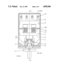
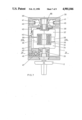
- FIG. 1 shows an axial section through a switch according to the invention
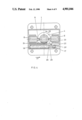
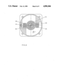
- FIG. 2 shows a section along line II--II of FIG. 1 with the switch assuming off-position
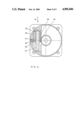
- FIG. 3 shows a section analogous to that of FIG. 2 with the switch assuming on-position
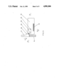
- FIG. 4 shows a section along line IV--IV of FIG. 2;
- FIG. 5 shows a top plan view of the toothed rack together with the rod actuating the auxiliary contacts and this in an enlarged scale, noting that FIG. 4 represents a section along line IV--IV of FIG. 5;
- FIG. 6 shows a section along line VI--VI of FIG. 1;
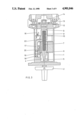
- FIG. 7 shows an axial section analogous to that of FIG. 1 through a second embodiment of a switch according to the invention
- FIG. 8 shows a section along line VIII--VIII of FIG. 7;
- FIG. 9 shows a section along line IX--IX of FIG. 7.
- FIG. 1 there is shown a switch comprising a switch housing 1.
- a rotary control grip 2 is rotatably supported on this housing 1 and cooperates via a cogging 3 with a rotary part 4.
- This part 4 comprises, as will become clear in connection with the following Figures, guide grooves 5 having the shape of a helix and being engaged by a part 6 being shiftable in axial direction.
- the axially shiftable part 6, which cooperates with the actuating member being designed as a rotary control grip, houses an armature magnet 7 consisting at least within the area of the front surfaces 7a of a material which is conductive for magnetic flux.
- At least that area of the front surfaces 7a of the magnet yoke 8a being located within the component part 9 opening and closing the switch contacts is equally formed of a material being conductive for magnetic flux.
- the parts 6 and 9 and, respectively, 7 and 8 comprise recesses accommodating a coil 10 being stationarily arranged (not shown in detail) relative to the housing of the switch.
- the front surfaces 7a and 8a being formed of a material being conductive for the magnetic flux, it is possible to drag along on account of the magnetic coupling between the front surfaces 7 and 8 the component part 9 opening and closing the switch contacts and to actuate the switch bridges being designated by the reference numeral 12 when actuating, in energized condition of the coil, the rotary control grip 12 and thus shifting the part 6 in direction of the arrow 11.
- the switch is shown in off-position.
- the helix-shaped guide means 5 effecting an axial shifting movement of the part 6 engaging this helix-shaped guide means on occasion of rotating the rotary control grip 2.
- the parts 8 and, respectively, 8a and 7 and, respectively, 7a consisting of a material being conductive for the magnetic flux can clearly be seen in FIG. 2.
- the component part 9 opening and closing the switch contacts carries electrically conductive bridges 13 being each supported by means of a spring 14.
- the electromagnet is formed of the magnet armature 7 and the magnet yoke 8 providing the closed magnetic circuit and of the coil 10 representing the electric circuit.
- each respective bridge 13 interconnects the switch contacts 12 as is more precisely shown in FIG. 3.
- screws 15 For the purpose of connecting the switch contacts 12 with external conduits, not shown in detail, there are provided screws 15.
- Reference numeral 16 represents an auxiliary contact cooperating with a rod 17.
- the auxiliary contact 16 serves the purpose to separately apply voltage to the coil 10.
- the rod 17 is supported against the force of a spring 18 and is equally moved in direction of the arrow 11 by a stop member or pin 20 cooperating with a toothed rack 19 cooperating with the rotatable part 4, and this when rotating the rotary control grip 2.
- the helix-shaped guide means 5 of the rotatable part 4 extends in its first partial area in nearly normal relation to the axial direction 21 of the switch, which provides the possibility that the rod 17 causes first closing the auxiliary contact 16 and thus energization of the electromagnet when initiating the rotary movement of the rotary control grip 2 on account of being taken along, as will be explained in the following with greater detail, via the toothed rack, whereupon the part 6 is shifted in direction of the arrow 11 when further rotating the rotary control grip.
- the coil 10 already being supplied with current at this moment, there results a force-locking coupling between the parts 7 and 8 formed of a material being conductive for the magnetic flux, so that it is possible to close the contacts 12.
- FIG. 3 shows the switch according to the invention in its on-position.
- the spring 14 exerts a pressing force on the electrically conductive bridge 13 and provides the contact pressure required for a reliable current flow.
- the rod 17 is secured by a stop 22 provided on the component part 9 opening and closing the switch contacts.
- the auxiliary contact 16 leading to the coil 10 which is in a pre-loaded condition for closing the contact, will be opened on occasion of a release caused by the electromagnet or on occasion of a switching-off operation.
- FIG. 4 there is more exactly shown how the toothed rack 19 cooperates with the rotary control grip.
- the rotatable part 4 has a cogging 23, which cooperates with a cogging 24 of the toothed rack.
- the toothed rack 19 is moved in direction of the arrow 27 against the force of a spring 26.
- the toothed rack 19 has in a partial area thereof a coulisse, into which is engaged the pin 20 of the rod 17.
- the toothed rack is moved in direction of the arrow 27, the rod is shifted in direction of the arrow 11, which results in closing the auxiliary contact 16 and thus in energizing the electromagnet as has been described above. If, however, no voltage is applied to the entry side of the switch, the electromagnet can not be activated and the component part 9 opening and closing the switch contacts can not be taken along when further rotating the rotary control grip 2.
- the electromagnet is energized, closing of the contacts will be effected on account of the force-locking coupling between the parts 7 and 8 and the rod 17 will be kept in its downwardly pressed position against the force of the spring 18 via the stop member 22 of the component part 9 opening and closing the switch contacts.
- the rod and the toothed rack are provided with pawls 28,29 which come in mutual engagement in the closed position of the switch contacts. In the closed position of the switch contacts, the pin 20 of the rod 17 assumes the position within the coulisse 30 shown in FIG. 5 in dashed lines.
- FIG. 6 shows that the part 9 is loaded by springs 32, which may, for example, be supported on the coil 10 and which cause on occasion of a release by the electromagnet the opening of the switch bridge and thus the interruption of the main current circuit.
- the release action shall in short be explained which is, for example, caused by underrunning voltage resulting in a reduction of the magnet force or by a voltage breakdown or by an interruption of the current circuit resulting in suppression of the magnet force.
- a release shall be effected by the electromagnet.
- the force acting at the front surfaces 7a and 8a is reduced or, respectively, suppressed and the component part 9 is moved under action of the force of the spring 32 in opposite direction to that of the arrow 11, which results in opening the switch contacts.
- the rod 17 loaded by the spring 18 moves in opposite direction to that of the arrow 11, because the rod 17 is no more maintained in the downwardly pressed position by the stop member 22 of the part 9.
- opening of the auxiliary contact 16 is achieved, which results in interrupting the current flow through the coil 10.
- this movement of the rod 17 also results in cancelling the locking action of the pawls 28 and 29, and the toothed rack 19 is moved by the force of the spring 26 in opposite direction to that of arrow 27.
- This movement of the toothed rack 19 causes, via the coggings 23 and 24, movement of the rotary control grip 2 in its off-position.
- the auxiliary contact 16 reliably assumes open position and the coil 10 can thus not again unintentionally be put to voltage.
- An essential feature of the switch according to the invention is the trip-free release, which means that, even if the control grip is blocked in the switched-on condition and the coil current circuit is being interrupted, the main contacts are, in spite thereof, brought in off-position.
- This is a safety feature required by many regulations and making sure that, for example, machines can not automatically start operation after a voltage breakdown. A new switching-on operation can thus only be started by actuating the rotary control grip 2, noting that there must reliably be provided for the premise that the coil 10 can be put to voltage via the auxiliary contact 16 for achieving coupling between the parts 6 and 9.
- the component part 9 opening and closing the switch contacts is coupled with the part 6 for closing the contacts 12 in direction of the arrow 11 against the force of the spring 32, while coupling under the action of pressure is effected for opening the contacts in opposite direction to that of the arrow 11 when actuating the rotary control grip.
- FIGS. 7 to 9 there is shown a second embodiment of a switch according to the invention.
- a rotary control grip 2 is again rotatably supported on a housing 1 and is coupled with a rotatable part 34 with interposition of a rotatable part 33.
- the part 34 is formed within the area of its front surface or, respectively, engaging surface 35 of a material being conductive for the magnetic flux, and this applies also to the front surface or, respectively, engaging surface 36 of a rotatable part 37.
- the parts 34 and 37 have within their interior recesses for accommodating a coil 10.
- a spiral spring is indicated by the reference numeral 38 by means of which spring the component part 37 opening and closing the switch contacts is loaded out of the take-along position for the closed position shown in FIG. 7.
- the part 37 is, via a profiled pin, coupled with a cam 55, and this cam actuates, via rods 39, the electrically conductive bridges 40 being supported via springs 41, noting that the cam exerts a rotating movement while the rods 39 and the switch bridges 40 exert a linear movement.
- the part 37 has a stop member 42 which maintains in closed position a rod cooperating with an auxiliary contact 43.
- the rod 44 is again loaded by a spring 45 and is moved, as will be described in greater detail in the following, by a toothed rack 46 being loaded by the force of a spring 47.
- FIG. 8 there is shown a section within the area of the front surfaces or, respectively, engaging surfaces 35 and 36.
- the engaging surfaces 35 being connected with the part 34 are rotated in direction of the arrow 48. If the coil 10 has been put under voltage by closing the auxiliary contact 43 when starting the rotating movement of the rotary control grip 2, the engaging surfaces 36 of the component part 37 opening and closing the switch contacts are taken along on account of the induced magnetic flux when moving the engaging surfaces 35 in direction of the arrow 48.
- the component part 37 opening or, respectively, closing the switch contact is also in this embodiment loaded by tension against the force of the spiral spring 38 when closing the contacts, while during the switching-off operation a load in opposite direction to that of the arrow 48 becomes effective by the pressure exerted by the engaging surfaces 35 on the surfaces 36.
- the actuation of the rod 44 for closing the auxiliary contact during the rotating movement of the rotary control grip 2 is effected in a similar manner as in connection with the first example of embodiment of the switch according to the invention (FIG. 9).
- a movement of the toothed rack 46 in direction of the arrow 51 against the force of the spring 47 is effected via coggings 49, 50.
- a pin 52 arranged on the rod 44 is again guided within a coulisse of the toothed rack which is of similar design as in the embodiment shown in FIG. 5.
- the toothed rack 46 and the rod 44 are again provided with pawls 53 and, respectively, 54, which, in closed position of the switch contacts, come in mutual engagement and provide a relief with respect to the spring force.
- this second embodiment of the switch according to the invention is effected in a similar manner as in connection with the first embodiment.
- a reduction or, respectively, suppression of the magnetic flux induced by the coil 10 in the front surfaces or, respectively, engaging surfaces 35 and 36 of the rotatable parts 34 and 37 there results rotation of the part 37 by the force of the spring 38 in opposite direction to that of the arrow 48.
- the stop member 42 is disengaged from the rod 44, which moves on account of the force of the spring 45 in direction to the auxiliary contact 43 and opens this contact.
- any release by the electromagnet is accompanied by an interruption of the coupling between the respective engaging surfaces or, respectively, front surfaces formed of a material being conductive for the magnetic flux, which results in opening the switch contacts.
- Switching-on of the switch according to the invention is only possible if voltage can be applied to the electromagnet by closing the auxiliary contacts and if thus is made possible a force-locking coupling between the actuating member and the component part opening and closing the switch contacts. After an electromagnetic release, the switch is automatically brought into its off-position, and the windings of the electromagnet can not again unintentionally be put under voltage in this off-position.
Landscapes
- Physics & Mathematics (AREA)
- Electromagnetism (AREA)
- Push-Button Switches (AREA)
- Driving Mechanisms And Operating Circuits Of Arc-Extinguishing High-Tension Switches (AREA)
- Switches With Compound Operations (AREA)
- Keying Circuit Devices (AREA)
- Rotary Switch, Piano Key Switch, And Lever Switch (AREA)
- Details Of Connecting Devices For Male And Female Coupling (AREA)
- Breakers (AREA)
- Switch Cases, Indication, And Locking (AREA)
- Switches That Are Operated By Magnetic Or Electric Fields (AREA)
- Magnetic Treatment Devices (AREA)
- Measurement And Recording Of Electrical Phenomena And Electrical Characteristics Of The Living Body (AREA)
- Adornments (AREA)
- Lock And Its Accessories (AREA)
- Braking Arrangements (AREA)
- Coupling Device And Connection With Printed Circuit (AREA)
- Relay Circuits (AREA)
- Switches Operated By Changes In Physical Conditions (AREA)
- Tumbler Switches (AREA)
- Electrophonic Musical Instruments (AREA)
Applications Claiming Priority (2)
| Application Number | Priority Date | Filing Date | Title |
|---|---|---|---|
| AT145587 | 1987-06-09 | ||
| AT1455/87 | 1987-06-09 |
Publications (1)
| Publication Number | Publication Date |
|---|---|
| US4901046A true US4901046A (en) | 1990-02-13 |
Family
ID=3514276
Family Applications (1)
| Application Number | Title | Priority Date | Filing Date |
|---|---|---|---|
| US07/198,580 Expired - Fee Related US4901046A (en) | 1987-06-09 | 1988-05-25 | Manually actuated on-off switch with electromagnetic release |
Country Status (15)
| Country | Link |
|---|---|
| US (1) | US4901046A (fr) |
| EP (1) | EP0295236B1 (fr) |
| JP (1) | JPH0644442B2 (fr) |
| AT (1) | ATE100630T1 (fr) |
| AU (1) | AU604913B2 (fr) |
| BR (1) | BR8802795A (fr) |
| CA (1) | CA1330355C (fr) |
| DE (1) | DE3887209D1 (fr) |
| DK (1) | DK167786B1 (fr) |
| ES (1) | ES2050168T3 (fr) |
| FI (1) | FI90807C (fr) |
| NO (1) | NO173411C (fr) |
| NZ (1) | NZ224935A (fr) |
| YU (1) | YU47414B (fr) |
| ZA (1) | ZA884132B (fr) |
Cited By (4)
| Publication number | Priority date | Publication date | Assignee | Title |
|---|---|---|---|---|
| US5861786A (en) * | 1996-07-02 | 1999-01-19 | Schneider Electric Sa | Safety switch that may be locked with an electromagnet |
| WO1999030339A1 (fr) * | 1997-12-05 | 1999-06-17 | Siemens Aktiengesellschaft | Unite appareil de commutation comprenant un appareil de commutation et un commutateur auxiliaire a avance de phase accouple |
| WO2001069635A1 (fr) * | 2000-03-17 | 2001-09-20 | Ge Power Controls France | Commande electrique de disjoncteur |
| US20090032379A1 (en) * | 2006-03-03 | 2009-02-05 | Socomec S.A. | Automated control module for electrical cut-off apparatus and electrical cut-off apparatus equipped with such a control module |
Families Citing this family (2)
| Publication number | Priority date | Publication date | Assignee | Title |
|---|---|---|---|---|
| JP4739551B2 (ja) * | 2001-03-01 | 2011-08-03 | 株式会社東海理化電機製作所 | シフト装置 |
| CN101217080B (zh) * | 2007-12-30 | 2012-09-26 | 人民电器集团有限公司 | 框架式断路器的复位机构 |
Citations (5)
| Publication number | Priority date | Publication date | Assignee | Title |
|---|---|---|---|---|
| US2591336A (en) * | 1948-03-05 | 1952-04-01 | Cons Vultee Aircraft Corp | Magnetic and manually operated electric switch |
| US2611843A (en) * | 1948-06-12 | 1952-09-23 | Rotax Ltd | Combined magnetic and manual switch |
| US3036174A (en) * | 1959-08-31 | 1962-05-22 | Bendix Corp | Manually operable rotary switch with electromagnetic on-off action and return action upon failure of energizing circuit |
| AT380973B (de) * | 1984-12-17 | 1986-08-11 | Naimer H L | Rueckstelleinrichtung |
| US4742401A (en) * | 1985-10-24 | 1988-05-03 | Dr. Ing. Rudolf Hell Gmbh | Opto-electronic scan head which has a housing portion and a housing member that are coupled together by first and second guide rods so as to allow relative motion therebetween |
Family Cites Families (4)
| Publication number | Priority date | Publication date | Assignee | Title |
|---|---|---|---|---|
| DE1114909B (de) * | 1960-03-28 | 1961-10-12 | Stotz Kontakt Gmbh | Installationsselbstschalter mit einer mechanischen und einer elektrischen Baueinheit, insbesondere in Schraubstoepselform |
| FR2517114A1 (fr) * | 1981-11-26 | 1983-05-27 | Alsthom Cgee | Commutateur electrique a commande rotative rappele automatiquement en l'absence de tension |
| AT374041B (de) * | 1982-03-25 | 1984-03-12 | Naimer H L | Stern-dreieck-schalter mit nullspannungsausloesung |
| DE3579597D1 (de) * | 1985-10-24 | 1990-10-11 | Square D Deutschland | Schaltgeraet. |
-
1988
- 1988-05-25 US US07/198,580 patent/US4901046A/en not_active Expired - Fee Related
- 1988-06-02 YU YU107988A patent/YU47414B/sh unknown
- 1988-06-06 AT AT88890138T patent/ATE100630T1/de not_active IP Right Cessation
- 1988-06-06 EP EP88890138A patent/EP0295236B1/fr not_active Expired - Lifetime
- 1988-06-06 DE DE88890138T patent/DE3887209D1/de not_active Expired - Fee Related
- 1988-06-06 ES ES88890138T patent/ES2050168T3/es not_active Expired - Lifetime
- 1988-06-07 NO NO882507A patent/NO173411C/no unknown
- 1988-06-08 CA CA000568986A patent/CA1330355C/fr not_active Expired - Fee Related
- 1988-06-08 NZ NZ224935A patent/NZ224935A/xx unknown
- 1988-06-08 AU AU17474/88A patent/AU604913B2/en not_active Ceased
- 1988-06-08 BR BR8802795A patent/BR8802795A/pt not_active IP Right Cessation
- 1988-06-08 DK DK310688A patent/DK167786B1/da not_active Application Discontinuation
- 1988-06-08 FI FI882718A patent/FI90807C/fi not_active IP Right Cessation
- 1988-06-09 JP JP63142734A patent/JPH0644442B2/ja not_active Expired - Lifetime
- 1988-06-09 ZA ZA884132A patent/ZA884132B/xx unknown
Patent Citations (5)
| Publication number | Priority date | Publication date | Assignee | Title |
|---|---|---|---|---|
| US2591336A (en) * | 1948-03-05 | 1952-04-01 | Cons Vultee Aircraft Corp | Magnetic and manually operated electric switch |
| US2611843A (en) * | 1948-06-12 | 1952-09-23 | Rotax Ltd | Combined magnetic and manual switch |
| US3036174A (en) * | 1959-08-31 | 1962-05-22 | Bendix Corp | Manually operable rotary switch with electromagnetic on-off action and return action upon failure of energizing circuit |
| AT380973B (de) * | 1984-12-17 | 1986-08-11 | Naimer H L | Rueckstelleinrichtung |
| US4742401A (en) * | 1985-10-24 | 1988-05-03 | Dr. Ing. Rudolf Hell Gmbh | Opto-electronic scan head which has a housing portion and a housing member that are coupled together by first and second guide rods so as to allow relative motion therebetween |
Cited By (7)
| Publication number | Priority date | Publication date | Assignee | Title |
|---|---|---|---|---|
| US5861786A (en) * | 1996-07-02 | 1999-01-19 | Schneider Electric Sa | Safety switch that may be locked with an electromagnet |
| WO1999030339A1 (fr) * | 1997-12-05 | 1999-06-17 | Siemens Aktiengesellschaft | Unite appareil de commutation comprenant un appareil de commutation et un commutateur auxiliaire a avance de phase accouple |
| US6326871B1 (en) | 1997-12-05 | 2001-12-04 | Siemens Aktiengesellschaft | Switchgear unit of a switching device and a coupled leading auxiliary switch |
| WO2001069635A1 (fr) * | 2000-03-17 | 2001-09-20 | Ge Power Controls France | Commande electrique de disjoncteur |
| FR2806523A1 (fr) * | 2000-03-17 | 2001-09-21 | Ge Power Controls France | Commande electrique de disjoncteur |
| US6441329B2 (en) | 2000-03-17 | 2002-08-27 | General Electric Company | Circuit breaker drive |
| US20090032379A1 (en) * | 2006-03-03 | 2009-02-05 | Socomec S.A. | Automated control module for electrical cut-off apparatus and electrical cut-off apparatus equipped with such a control module |
Also Published As
| Publication number | Publication date |
|---|---|
| DK167786B1 (da) | 1993-12-13 |
| DK310688A (da) | 1988-12-10 |
| JPH0644442B2 (ja) | 1994-06-08 |
| FI882718A7 (fi) | 1988-12-10 |
| ES2050168T3 (es) | 1994-05-16 |
| AU604913B2 (en) | 1991-01-03 |
| NO173411B (no) | 1993-08-30 |
| DK310688D0 (da) | 1988-06-08 |
| FI882718A0 (fi) | 1988-06-08 |
| ZA884132B (en) | 1989-02-22 |
| NO882507D0 (no) | 1988-06-07 |
| FI90807C (fi) | 1994-03-25 |
| BR8802795A (pt) | 1989-01-03 |
| ATE100630T1 (de) | 1994-02-15 |
| NO173411C (no) | 1993-12-08 |
| EP0295236A2 (fr) | 1988-12-14 |
| DE3887209D1 (de) | 1994-03-03 |
| JPS643935A (en) | 1989-01-09 |
| EP0295236B1 (fr) | 1994-01-19 |
| CA1330355C (fr) | 1994-06-21 |
| NO882507L (no) | 1988-12-12 |
| FI90807B (fi) | 1993-12-15 |
| EP0295236A3 (en) | 1990-05-23 |
| YU47414B (sh) | 1995-03-27 |
| YU107988A (en) | 1991-02-28 |
| AU1747488A (en) | 1988-12-15 |
| NZ224935A (en) | 1990-09-26 |
Similar Documents
| Publication | Publication Date | Title |
|---|---|---|
| US4725799A (en) | Circuit breaker with remote control | |
| JPH0349173B2 (fr) | ||
| JPS6258095B2 (fr) | ||
| US4947145A (en) | Remote-controlled circuit breaker | |
| US5982258A (en) | Tripping device for a circuit breaker equipped with an electrical fault indication | |
| JPS61121231A (ja) | 遮断器 | |
| JPH0765688A (ja) | 接触器/保護継電器型保護開閉器 | |
| US4901046A (en) | Manually actuated on-off switch with electromagnetic release | |
| JPH02100230A (ja) | 遠隔操作式回路遮断器 | |
| US5293521A (en) | Protective relay switch having trap door | |
| JPH01283733A (ja) | 電磁石によって制御される接点を有するスイッチ装置 | |
| JPH0152846B2 (fr) | ||
| US3784940A (en) | Circuit breaker with overcurrent and auxiliary releases | |
| US4368443A (en) | Power electric circuit switching device | |
| CN101223619B (zh) | 断路器 | |
| EP1017080B1 (fr) | Dipositif auxiliaire | |
| EP1209711A1 (fr) | Dipositif auxiliaire | |
| KR920004652B1 (ko) | 원격조작식 회로차단기 | |
| RU2006092C1 (ru) | Пускатель с ручным приводом | |
| KR900009089Y1 (ko) | 솔레노이드 투입식 고압개폐기의 투입상태 분산 유지장치 | |
| JPS648406B2 (fr) | ||
| JPS6110824A (ja) | リモ−トコントロ−ル式回路しや断器 | |
| AT245090B (de) | Druck- oder Schwimmerwächter mit Motorschutzeinrichtung | |
| EP3384511A1 (fr) | Dispositif de déconnexion et agencement pour déconnecter un contacteur | |
| KR890005149Y1 (ko) | 열동식 과전류 계전기 |
Legal Events
| Date | Code | Title | Description |
|---|---|---|---|
| AS | Assignment |
Owner name: HUBERT LAURENZ NAIMER, CH-6612 ASCONA, NUVOLA BIAN Free format text: ASSIGNMENT OF ASSIGNORS INTEREST.;ASSIGNOR:GOTTFRIED, ALSCH;REEL/FRAME:004923/0720 Effective date: 19880516 Owner name: HUBERT LAURENZ NAIMER,SWITZERLAND Free format text: ASSIGNMENT OF ASSIGNORS INTEREST;ASSIGNOR:GOTTFRIED, ALSCH;REEL/FRAME:004923/0720 Effective date: 19880516 |
|
| FPAY | Fee payment |
Year of fee payment: 4 |
|
| REMI | Maintenance fee reminder mailed | ||
| LAPS | Lapse for failure to pay maintenance fees | ||
| FP | Lapsed due to failure to pay maintenance fee |
Effective date: 19980218 |
|
| STCH | Information on status: patent discontinuation |
Free format text: PATENT EXPIRED DUE TO NONPAYMENT OF MAINTENANCE FEES UNDER 37 CFR 1.362 |