US4909767A - Propulsion unit for inboard-outboard motor - Google Patents
Propulsion unit for inboard-outboard motor Download PDFInfo
- Publication number
- US4909767A US4909767A US07/252,683 US25268388A US4909767A US 4909767 A US4909767 A US 4909767A US 25268388 A US25268388 A US 25268388A US 4909767 A US4909767 A US 4909767A
- Authority
- US
- United States
- Prior art keywords
- shaft
- bevel gear
- outboard drive
- set forth
- gear
- Prior art date
- Legal status (The legal status is an assumption and is not a legal conclusion. Google has not performed a legal analysis and makes no representation as to the accuracy of the status listed.)
- Expired - Lifetime
Links
- 230000002441 reversible effect Effects 0.000 claims description 22
- 230000005540 biological transmission Effects 0.000 claims description 8
- 238000010276 construction Methods 0.000 description 10
- 230000007935 neutral effect Effects 0.000 description 6
- 125000006850 spacer group Chemical group 0.000 description 6
- 238000002485 combustion reaction Methods 0.000 description 3
- 238000009434 installation Methods 0.000 description 2
- 230000000295 complement effect Effects 0.000 description 1
- 238000011068 loading method Methods 0.000 description 1
- 230000004048 modification Effects 0.000 description 1
- 238000012986 modification Methods 0.000 description 1
- 230000008707 rearrangement Effects 0.000 description 1
Images


Classifications
-
- B—PERFORMING OPERATIONS; TRANSPORTING
- B63—SHIPS OR OTHER WATERBORNE VESSELS; RELATED EQUIPMENT
- B63H—MARINE PROPULSION OR STEERING
- B63H20/00—Outboard propulsion units, e.g. outboard motors or Z-drives; Arrangements thereof on vessels
- B63H20/14—Transmission between propulsion power unit and propulsion element
- B63H20/20—Transmission between propulsion power unit and propulsion element with provision for reverse drive
-
- B—PERFORMING OPERATIONS; TRANSPORTING
- B63—SHIPS OR OTHER WATERBORNE VESSELS; RELATED EQUIPMENT
- B63H—MARINE PROPULSION OR STEERING
- B63H20/00—Outboard propulsion units, e.g. outboard motors or Z-drives; Arrangements thereof on vessels
- B63H20/14—Transmission between propulsion power unit and propulsion element
- B63H20/22—Transmission between propulsion power unit and propulsion element allowing movement of the propulsion element about at least a horizontal axis without disconnection of the drive, e.g. using universal joints
-
- F—MECHANICAL ENGINEERING; LIGHTING; HEATING; WEAPONS; BLASTING
- F02—COMBUSTION ENGINES; HOT-GAS OR COMBUSTION-PRODUCT ENGINE PLANTS
- F02B—INTERNAL-COMBUSTION PISTON ENGINES; COMBUSTION ENGINES IN GENERAL
- F02B61/00—Adaptations of engines for driving vehicles or for driving propellers; Combinations of engines with gearing
- F02B61/04—Adaptations of engines for driving vehicles or for driving propellers; Combinations of engines with gearing for driving propellers
- F02B61/045—Adaptations of engines for driving vehicles or for driving propellers; Combinations of engines with gearing for driving propellers for marine engines
-
- Y—GENERAL TAGGING OF NEW TECHNOLOGICAL DEVELOPMENTS; GENERAL TAGGING OF CROSS-SECTIONAL TECHNOLOGIES SPANNING OVER SEVERAL SECTIONS OF THE IPC; TECHNICAL SUBJECTS COVERED BY FORMER USPC CROSS-REFERENCE ART COLLECTIONS [XRACs] AND DIGESTS
- Y10—TECHNICAL SUBJECTS COVERED BY FORMER USPC
- Y10T—TECHNICAL SUBJECTS COVERED BY FORMER US CLASSIFICATION
- Y10T74/00—Machine element or mechanism
- Y10T74/19—Gearing
- Y10T74/19219—Interchangeably locked
-
- Y—GENERAL TAGGING OF NEW TECHNOLOGICAL DEVELOPMENTS; GENERAL TAGGING OF CROSS-SECTIONAL TECHNOLOGIES SPANNING OVER SEVERAL SECTIONS OF THE IPC; TECHNICAL SUBJECTS COVERED BY FORMER USPC CROSS-REFERENCE ART COLLECTIONS [XRACs] AND DIGESTS
- Y10—TECHNICAL SUBJECTS COVERED BY FORMER USPC
- Y10T—TECHNICAL SUBJECTS COVERED BY FORMER US CLASSIFICATION
- Y10T74/00—Machine element or mechanism
- Y10T74/19—Gearing
- Y10T74/19219—Interchangeably locked
- Y10T74/19377—Slidable keys or clutches
- Y10T74/19414—Single clutch shaft
- Y10T74/19484—Single speed forward and reverse
- Y10T74/19493—Bevel gears
Definitions
- This invention relates to a propulsion unit for an inboard-outboard motor and more particularly to an improved propulsion unit that lends itself to reversal of the rotation of the propulsion device in a simple and expedient manner for twin outboard drive arrangements.
- a marine outboard drive generally has a side thrust due to the direction of rotation of either the propeller or other propulsion device. This side thrust may be countered by employing twin counterrotating outboard drives. For this and a variety of other reasons, it has been increasing practice to use such twin outboard drives, be they outboard motors or the outboard drive unit of an inboard-outboard arrangement.
- each outboard drive normally there is a separate internal combustion engine that powers each outboard driven.
- the internal combustion engines In order to achieve the counterrotation of the outboard drives, either the internal combustion engines must rotate in opposite directions or the gearing associated in the drive between the engine and the propulsion device must include a reversing mechanism for reversing the direction of rotation.
- each outboard drive normally includes its own forward, neutral, reverse transmission so as to permit propulsion of the watercraft in either forward or reverse directions.
- outboard drives either outboard motors or inboard-outboard drives
- inboard-outboard drives may be used either singly or in pairs
- twin installations This presents problems in connection with twin installations since, as aforenoted, the drives should rotate in opposite directions in such applications.
- This invention is adapted to be embodied in a marine outboard drive that is comprised of a first shaft driven by an engine and rotating in a fixed direction.
- a second shaft is rotatable about an axis that is non-parallel with the first shaft.
- a propulsion unit is driven from the second shaft through a forward, neutral, reverse transmission for driving the propulsion unit in selected forward or reverse directions.
- reversible means are provided for driving the second shaft from the first shaft in selected forward or reverse directions.
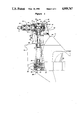
- FIG. 1 is a side elevational view, with portions shown in section, of a marine outboard drive constructed in accordance with an embodiment of the invention and set up for rotation in a first direction.
- FIG. 2 is an enlarged view showing a portion of the construction illustrated in FIG. 1 and set up for counterrotation.
- FIG. 3 is an enlarged cross-sectional view taken along the line 3--3 of FIG. 2.
- FIG. 4 is an enlarged cross-sectional view taken along the line 4--4 of FIG. 2.
- FIG. 5 is an enlarged front elevational view of one of the gears of the forward, reverse transmission of the lower unit.
- FIG. 6 is a cross-sectional view taken along the line 6--6 of FIG. 5 and shows a comparison between the construction in accordance with the invention and the prior art, the latter being shown in phantom.
- FIG. 7 is an enlarged end elevational view of the face of the dog clutching element that mates with the driven gear shown in FIGS. 5 and 6.
- FIG. 8 is an enlarged cross-sectional view taken along the line 8--8 of FIG. 7 showing the comparison between the construction in accordance with the invention, as shown in solid lines and the prior art as shown in phantom lines.
- a marine outboard drive constructed in accordance with an embodiment of the invention is identified generally by the reference numeral 11.
- the outboard drive 11 is comprised of the outboard drive unit of an inboard-outboard drive. It is to be understood, however, that certain facets of the invention may be applied equally as well with outboard motors. The invention, however, has particular utility in connection with arrangements where it is desirable to have the outboard drive and specifically its propulsion unit rotate in either normal or counterrotation modes.
- the outboard drive 11 is powered by a remotely positioned internal combustion engine (not shown) which drives an input shaft 12 that rotates in a constant direction, indicated generally by the arrow A and which is, in the illustrated construction, counterclockwise.
- the drive shaft 12 is coupled by means of a universal joint 13 to an input shaft 14 of the outboard drive 11.
- the input shaft 14 has an extending portion 15 that is journaled within an outer housing 16 of the outboard drive 11 by means of a pair of spaced apart thrust bearings 17 and 18, in a manner to be described.
- a vertically extending drive shaft 19 is supported in the housing 16 by means of bearings to be described and depends into a lower unit 21.
- the drive shaft 19 is driven from the input shaft 15, in a manner to be described, so as to rotate either in a forward direction indicated by the arrow B in FIG. 1 or a reverse or counterdirection indicated by the arrow C in FIG. 2.
- the drive shaft 19 is journaled by means of a first thrust bearing 22 that is positioned between the drive shaft housing 16 and lower unit housing 21 and an anti-friction bearing 23 which is journaled adjacent it.
- the thrust bearing 22 is designed to take vertically upward thrusts transmitted to the drive shaft 19.
- a bevel gear 24 is affixed for rotation with the drive shaft 19 in a known manner.
- the bevel gear 24 forms a portion of a forward, neutral, reverse transmission, indicated generally by the reference numeral 25.
- the forward, neutral, reverse transmission 25 includes a pair of counterrotating bevel gears comprised of a forward drive gear 26 and a reverse drive gear 27 that are in mesh with the driving bevel gear 24 on diametrically opposite sides of it.
- the bevel gears 26 and 27 are journaled upon a propeller shaft 28 to which a propulsion device such as a propeller 29 is affixed in a known manner.
- a dog clutching sleeve 31 has a splined connection with the propeller shaft 28 so as to rotate with it and also to be axially movable along it.
- a shifting mechanism shown partially at 32, is provided for shifting the dog clutching sleeve 31 between a neutral position as shown in FIG. 1 and a forward position wherein the dog clutching sleeve 31 rotatably couples the forward bevel gear 26 with the propeller shaft 28.
- the shifting mechanism 32 may shift the dog clutching sleeve 31 rearwardly so as to engage with the reverse gear 27 so as to rotatably couple this gear with the propeller shaft 28 for driving the propeller 29 in a reverse direction.
- This mechanism is generally conventional and, for that treason, further description of it is not believed to be necessary to understand the construction and operation of the invention features of this embodiment.
- a bevel gear 33 is affixed to the upper end of the drive shaft 19.
- the bevel gear 33 has its pitch circle arranged so that it intersects a point 34 at which the input shaft 15 is intersected by the axis of rotation of the drive shaft 19.
- the upper end of the drive shaft 19 and specifically the driven bevel gear 33 is supported by means of a double taper bearing 35 so as to take driving thrusts on the bevel gear 33 in opposite directions.
- the drive shaft 19 is adapted to be rotated in either the forward B or reverse C directions by the mechanism now to be described.
- the thrust bearing 35 is designed to take thrusts in either direction.
- the input shaft portion 15 is provided with spaced splined sections 36 and 37 that are spaced equidistant from the point of intersection 34 of the input shaft 14 and the drive shaft 19.
- a driving bevel gear 38 is designed to be selectively engaged with either the splined section 36 (FIG. 1) forward rotation in the direction of the arrow B or with the splined section 37 (FIG. 2) for counterrotation in the direction of the arrow C.
- a spacer sleeve 39 cooperates with the bevel gear 38 so as to insure proper alignment in each condition.
- the spacer sleeve 39 is formed with a hub portion 41 which is complementary in configuration to a hub portion 42 of the bevel gear 38 so as to facilitate this reversing in the direction of rotation.
- the hub 42 of the driving bevel gear 38 is journaled in the thrust bearing 17 and the hub 41 of the spacer shaft 39 is journaled in the thrust bearing 18.
- the assemblage is held together by means of a lock nut 43 and lock washer 44 that are received on a threaded end of the input shaft 14.
- a bearing cap 45 serves to hold and locate the thrust bearing 18.
- a bearing cap 46 holds and locates the thrust bearing 17.
- a removable cover plate 47 affords access to the nut 43 so as to facilitate reversal of the bevel gear 38 and spacer sleeve 39 on the input shaft section 16 for reversal of the direction of rotation.
- Shims 48 are interposed between the thrust bearings 17 and 18 and the gear 38 and spacer sleeve 39 so as to provide axial alignment between the bevel gears 38 and 33.
- the spacing sleeve 39 does not have any splined internal surface but merely has a bore that will clear the splines 36 or 37. If desired, however, there could be incorporated a splined connection between the spacer sleeve and the splines 36 and 37 of the input shaft portion 15.
- the dog clutching teeth of the forward, neutral, reverse transmission 25 are designed so as to accommodate the opposite directions of rotation of the drive shaft 16.
- the bevel gear 26 has dog clutching teeth 49 which face the bevel gear 27.
- Corresponding dog clutching teeth are formed on the driven gear 27.
- the dog clutching sleeve 31 (FIGS. 7 and 8) has dog clutching teeth 51 at its opposite sides which face the respective dog clutching teeth of the gears 26 and 27.
- the dog clutching teeth 49 and 51 are asymmetric in cross sections (FIGS. 6 and 7). That is, the dog clutching teeth 49 have a first driving face 52 and an inclined non-driving face 53.
- the dog clutching teeth 51 have a driving face 54 and a non-driving face 55.
- both faces of the teeth 49 and 51 are configured as at 52 and 54 so as to accommodate drive in opposite direction.
Landscapes
- Chemical & Material Sciences (AREA)
- Engineering & Computer Science (AREA)
- Combustion & Propulsion (AREA)
- Mechanical Engineering (AREA)
- Ocean & Marine Engineering (AREA)
- Structure Of Transmissions (AREA)
- Gear Transmission (AREA)
Applications Claiming Priority (2)
| Application Number | Priority Date | Filing Date | Title |
|---|---|---|---|
| JP62249484A JP2545409B2 (ja) | 1987-10-02 | 1987-10-02 | 船内外機の駆動ユニット |
| JP62-249484 | 1987-10-02 |
Publications (1)
| Publication Number | Publication Date |
|---|---|
| US4909767A true US4909767A (en) | 1990-03-20 |
Family
ID=17193656
Family Applications (1)
| Application Number | Title | Priority Date | Filing Date |
|---|---|---|---|
| US07/252,683 Expired - Lifetime US4909767A (en) | 1987-10-02 | 1988-10-03 | Propulsion unit for inboard-outboard motor |
Country Status (2)
| Country | Link |
|---|---|
| US (1) | US4909767A (ja) |
| JP (1) | JP2545409B2 (ja) |
Cited By (5)
| Publication number | Priority date | Publication date | Assignee | Title |
|---|---|---|---|---|
| US5238433A (en) * | 1991-06-10 | 1993-08-24 | Yamaha Hatsudoki Kabushiki Kaisha | Cover for the inboard-outboard motor |
| US5327793A (en) * | 1991-02-05 | 1994-07-12 | Yamaha Hatsudoki Kabushiki Kaisha | Thrust bearings and bevel gears arrangement of marine propulsion unit |
| US5501623A (en) * | 1994-10-14 | 1996-03-26 | Bowen, Iii; Perry G. | Propeller drive |
| US6585545B1 (en) * | 2002-02-06 | 2003-07-01 | Bombardier Motor Corperation Of America | Shielded tilt-trim subsystem for boats using a stern drive system |
| US7104853B1 (en) | 2003-03-19 | 2006-09-12 | Robert Thomas Kepka | Marine gimbal outdrive assembly |
Families Citing this family (1)
| Publication number | Priority date | Publication date | Assignee | Title |
|---|---|---|---|---|
| CN104797852A (zh) * | 2012-11-21 | 2015-07-22 | 爱信Ai株式会社 | 变速器 |
Citations (4)
| Publication number | Priority date | Publication date | Assignee | Title |
|---|---|---|---|---|
| US3871325A (en) * | 1973-01-11 | 1975-03-18 | Sidney W Raulerson | Marine drive system |
| US3888203A (en) * | 1974-03-29 | 1975-06-10 | Kiekhaefer Aeromarine Motors | Stern drive for boats |
| US4318702A (en) * | 1980-01-11 | 1982-03-09 | Stacey John C | Shifting mechanism for outboard motors |
| US4650428A (en) * | 1985-04-15 | 1987-03-17 | Outboard Marine Corporation | Marine propulsion device with floating drive shaft |
-
1987
- 1987-10-02 JP JP62249484A patent/JP2545409B2/ja not_active Expired - Fee Related
-
1988
- 1988-10-03 US US07/252,683 patent/US4909767A/en not_active Expired - Lifetime
Patent Citations (4)
| Publication number | Priority date | Publication date | Assignee | Title |
|---|---|---|---|---|
| US3871325A (en) * | 1973-01-11 | 1975-03-18 | Sidney W Raulerson | Marine drive system |
| US3888203A (en) * | 1974-03-29 | 1975-06-10 | Kiekhaefer Aeromarine Motors | Stern drive for boats |
| US4318702A (en) * | 1980-01-11 | 1982-03-09 | Stacey John C | Shifting mechanism for outboard motors |
| US4650428A (en) * | 1985-04-15 | 1987-03-17 | Outboard Marine Corporation | Marine propulsion device with floating drive shaft |
Cited By (5)
| Publication number | Priority date | Publication date | Assignee | Title |
|---|---|---|---|---|
| US5327793A (en) * | 1991-02-05 | 1994-07-12 | Yamaha Hatsudoki Kabushiki Kaisha | Thrust bearings and bevel gears arrangement of marine propulsion unit |
| US5238433A (en) * | 1991-06-10 | 1993-08-24 | Yamaha Hatsudoki Kabushiki Kaisha | Cover for the inboard-outboard motor |
| US5501623A (en) * | 1994-10-14 | 1996-03-26 | Bowen, Iii; Perry G. | Propeller drive |
| US6585545B1 (en) * | 2002-02-06 | 2003-07-01 | Bombardier Motor Corperation Of America | Shielded tilt-trim subsystem for boats using a stern drive system |
| US7104853B1 (en) | 2003-03-19 | 2006-09-12 | Robert Thomas Kepka | Marine gimbal outdrive assembly |
Also Published As
| Publication number | Publication date |
|---|---|
| JP2545409B2 (ja) | 1996-10-16 |
| JPH0194099A (ja) | 1989-04-12 |
Similar Documents
| Publication | Publication Date | Title |
|---|---|---|
| US4400163A (en) | Marine propulsion device including an overdrive transmission | |
| US4887982A (en) | Gear driven marine propulsion system with steerable gearcase and dual counterrotating propellers | |
| US4932907A (en) | Chain driven marine propulsion system with steerable gearcase and dual counterrotating propellers | |
| US4302196A (en) | Marine propulsion unit including propeller shaft thrust transmitting means | |
| US4887983A (en) | Chain drive marine propulsion system with dual counterrotating propellers | |
| US4869121A (en) | Marine propulsion unit with improved drive shaft arrangement | |
| US5494466A (en) | Transmission for dual propellers driven by an inboard marine engine | |
| US4792314A (en) | Marine drive with floating spider differential assembly | |
| JPH06156377A (ja) | 二重プロペラ式船用駆動装置 | |
| US4173939A (en) | Two-speed transmission | |
| KR910007958B1 (ko) | 배의 추진구동장치 및 이를 이용한 배 | |
| US3492966A (en) | Outboard drive unit for watercraft | |
| US4689027A (en) | Transmission mechanism for a marine outboard drive | |
| US4957460A (en) | Thrust bearing arrangement for marine outboard drives | |
| EP3551530B1 (en) | Strut mounted gear box for counter rotating propellers | |
| US4969370A (en) | Bearing structure for intermediate transmission shaft in vessel propulsion machine | |
| US5059144A (en) | Ahead/astern shifting device for marine propulsion unit | |
| US5890938A (en) | Marine counter-rotational propulsion system | |
| JPS5996092A (ja) | 2重反転プロペラ装置 | |
| KR910016568A (ko) | 선박 추진용 2중 프로펠러 반전장치 | |
| US4946409A (en) | Lubricating device for power device of inboard/outboard unit | |
| US4919630A (en) | Inboard drive system for a marine craft | |
| US3750616A (en) | Power transmission system | |
| JP2545409B2 (ja) | 船内外機の駆動ユニット | |
| CA1302797C (en) | Counter-rotation transmission |
Legal Events
| Date | Code | Title | Description |
|---|---|---|---|
| AS | Assignment |
Owner name: SANSHIN KOGYO KABUSHIKI KAISHA, 1400 NIPPASHI, HAM Free format text: ASSIGNMENT OF ASSIGNORS INTEREST.;ASSIGNOR:HAYASAKA, KENICHI;REEL/FRAME:004954/0723 Effective date: 19880929 Owner name: SANSHIN KOGYO KABUSHIKI KAISHA, 1400 NIPPASHI, HAM Free format text: ASSIGNMENT OF ASSIGNORS INTEREST;ASSIGNOR:HAYASAKA, KENICHI;REEL/FRAME:004954/0723 Effective date: 19880929 |
|
| STCF | Information on status: patent grant |
Free format text: PATENTED CASE |
|
| FPAY | Fee payment |
Year of fee payment: 4 |
|
| FEPP | Fee payment procedure |
Free format text: PAYOR NUMBER ASSIGNED (ORIGINAL EVENT CODE: ASPN); ENTITY STATUS OF PATENT OWNER: LARGE ENTITY |
|
| FPAY | Fee payment |
Year of fee payment: 8 |
|
| FPAY | Fee payment |
Year of fee payment: 12 |