US4942668A - Digital inclinometer - Google Patents
Digital inclinometer Download PDFInfo
- Publication number
- US4942668A US4942668A US07/192,809 US19280988A US4942668A US 4942668 A US4942668 A US 4942668A US 19280988 A US19280988 A US 19280988A US 4942668 A US4942668 A US 4942668A
- Authority
- US
- United States
- Prior art keywords
- output lead
- electrically connected
- index
- multivibrator
- comparator
- Prior art date
- Legal status (The legal status is an assumption and is not a legal conclusion. Google has not performed a legal analysis and makes no representation as to the accuracy of the status listed.)
- Expired - Fee Related
Links
Images



Classifications
-
- G—PHYSICS
- G01—MEASURING; TESTING
- G01B—MEASURING LENGTH, THICKNESS OR SIMILAR LINEAR DIMENSIONS; MEASURING ANGLES; MEASURING AREAS; MEASURING IRREGULARITIES OF SURFACES OR CONTOURS
- G01B11/00—Measuring arrangements characterised by the use of optical techniques
- G01B11/26—Measuring arrangements characterised by the use of optical techniques for measuring angles or tapers; for testing the alignment of axes
-
- G—PHYSICS
- G01—MEASURING; TESTING
- G01C—MEASURING DISTANCES, LEVELS OR BEARINGS; SURVEYING; NAVIGATION; GYROSCOPIC INSTRUMENTS; PHOTOGRAMMETRY OR VIDEOGRAMMETRY
- G01C9/00—Measuring inclination, e.g. by clinometers, by levels
- G01C9/02—Details
- G01C9/06—Electric or photoelectric indication or reading means
-
- G—PHYSICS
- G01—MEASURING; TESTING
- G01C—MEASURING DISTANCES, LEVELS OR BEARINGS; SURVEYING; NAVIGATION; GYROSCOPIC INSTRUMENTS; PHOTOGRAMMETRY OR VIDEOGRAMMETRY
- G01C9/00—Measuring inclination, e.g. by clinometers, by levels
- G01C9/12—Measuring inclination, e.g. by clinometers, by levels by using a single pendulum
Definitions
- This invention pertains to a digital means of sensing and displaying the angular position of a surface relative to a known reference such as horizontal level.
- the invention provides the user, such as a carpenter or other tradesperson, with a quick and accurate method of determining the relative angle of a surface.
- the standard spirit level which is typically used to determine if a surface is level or plumb provides a rugged and accurate means of accomplishing its purpose. In situations where an angle other than level or plumb is to be measured the spirit level does not provide the necessary flexibility, and in many cases it compromises accuracy.
- electronic inclinometers have been developed which provide a digital readout of angular displacement. Some of these inclinometers measure the relative angle using analog techniques, with the analog signal being converted to a digital signal using well-known methods. An example would be the AngleStarTM manufactured by Sperry, which uses a dielectric fluid between capacitance plates to sense angular position.
- the position of the liquid between the plates is a function of the angle of the surface being measured and thus modifies the inter-plate dielectric and, hence, the capacitance.
- the electronic circuitry After the analog signal is converted to a digital signal the electronic circuitry provides a digital readout of the surface angle over a limited angular rotation.
- Another digital inclinometer is presently marketed by Heath (Zenith), Model SM-2370, which uses a pendulum system to which is attached an encoder disk such that movement of the pendulum allows an optical sensing means to produce digital signals which can be counted and displayed by appropriate circuitry.
- This product provides one-half degree resolution over a range of plus or minus one hundred twenty degrees from level. Two other techniques for measuring surface angles are described in U.S. Pat. No.
- the present invention provides a system which overcomes the shortcomings listed above by eliminating the need for analog to digital conversion, and allows for operation over a full 360 degree rotation.
- a horizontal tilt sensor is fixed on a rotatable encoder, typically a disk.
- the encoder disk rotates on a shaft in a housing.
- the encoder disk has an index on it.
- the horizontal tilt sensor senses that the encoder is in a horizontal orientation.
- the encoder disk then rotates to the point where the index is detected by an index sensor fixed to the housing.
- the amount of rotation by the encoder disk between the horizontal orientation and the detection of the index is digitally measured and displayed on a digital display as being the angle of the housing relative to horizontal.
- the present invention is a rotatable disk with a horizontal tilt sensor on it and also an index mark.
- An index sensor detects the index mark, and then an electronic circuit digitally counts the amount of rotation of the disk from the time of detection of the index mark until the disk is in a horizontal position as detected by the horizontal tilt sensor. The amount of rotation counted is the inclination to be measured.
- the tilt sensor in one embodiment, is configured to sense a reference orientation of the encoder other than horizontal.
- One embodiment of the present invention utilizes an encoder disk which is rotated through 360 degrees using a small direct current drive motor, and an associated optical system which produces two digital signals.
- One signal results from the sensing of light through a narrow index window at an inner radius of the encoder disk. This signal references a particular starting point in the rotational position of the disk.
- the second signal results from light which is alternately interrupted by equally spaced opaque stripes located around the otherwise transparent outer circumference of the encoder disk. Since each opaque stripe (or the corresponding transparent stripe) can represent a whole or fractional degree of angular rotation, counting the number of stripes passing through the optical sensing system provides a means of determining angular rotation from the reference index window.
- a tilt sensor fixed to the encoder disk which determines when the encoder disk has just passed through a horizontal level position and produces a third signal in response thereto.
- the three signals just described when used with a presettable up/down digital counter, provide a means of determining the angular position of the encoder relative to horizontal.
- the resulting digital count is displayed on an appropriate system such as a multi-digit liquid crystal display (LCD) or light-emitting diode (LED) display.
- LCD liquid crystal display
- LED light-emitting diode
- Another embodiment of the present invention substitutes a stepper motor to rotate the encoder assembly rather than the D.C. motor. This also permits elimination of the opaque stripe portion of the encoder disk and its associated light detection means.
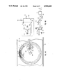
- FIGS. 1A and 1B show front and sectional views of one embodiment of the encoder system and the associated optical sensing means and tilt sensor of this invention.
- FIG. 1C shows an expanded view of the tilt sensor of this invention.
- FIG. 2 shows a series of typical timing waveforms produced by the embodiment of the present invention shown in FIGS. 1A and 1B.
- FIG. 3 is a schematic diagram of the electronic circuit utilized in the embodiment of the present invention shown in FIGS. 1A and 1B.
- FIG. 4A shows a second alternate means of sensing the tilt of the encoder system in accordance with this invention, using a spirit level and associated light detecting means.
- FIG. 4B shows the schematic diagram of the light detecting means used with the second alternate tilt sensor shown in FIG. 4A.
- FIG. 5 shows an alternate means of determining angular rotation using a stepper motor.
- the encoder assembly 3 contains two encoder mounting sections 1 and 2 which hold between them the encoder disk 4 and allow rotation of the same on shafts 19 and 20 in conjunction with bushings 21 and 22.
- Mounting sections 1 and 2 are made of non-conductive material such as plastic and are arranged such that once the encoder disk 4 is accurately located relative to the rotational center of the mounting sections 1 and 2, the sections 1 and 2 are cemented or otherwise fastened together.
- the encoder disk 4 is composed of a photographic film or a thin glass plate, or other appropriate material on which is produced a pattern consisting of areas that either inhibit or permit transmission of light through the disk.
- LED 6 Light emitting diode (LED) 6 floods an area of the encoder disk 4 with light which is typically in, but not restricted to, the infrared spectrum.
- Phototransistor 7 senses the variation in light intensity received from LED 6 as the encoder disk rotates.
- Phototransistor 8 receives light from LED 6 when the narrow index window 5 is rotationally positioned between the latter two elements.
- Tilt sensor 10 in this embodiment is shown in FIG. 1A in three different positions 14, 15 and 16 representing three different angles of rotation of the electronic level.
- Tilt sensor 10 is shown as a vial containing a mercury pool 13 which is allowed to move within the vial depending on the rotational position of the encoder assembly 3 and hence the position of the encoder disk 4.
- position 14 represents the condition when the index window 5 is positioned as shown.
- Position 15 represents the condition after the encoder assembly 3 has rotated counter-clockwise by 90 degrees.
- the mercury pool 13 will just initiate the closure of an electrically conductive path between contacts 11 and 12.
- FIG. 1C shows an expanded view of tilt sensor 10 in horizontal position 16. Note that mercury pool 13 contacts both contacts 11 and 12, to which are connected respectively wires 18 and 17. This contact closure will be used by associated electronic circuits whose function will be explained later.
- Wires 18 and 17 are used to connect the contacts 11 and 12 inside tilt sensor 10 to the metal shafts 19 and 20 comprising the rotational axis of the encoder system as shown in FIG. 1B.
- Bushings 21 and 22 are composed of a metal material such as bronze impregnated with a graphite lubricant, which serve a secondary purpose of providing rotating electrical contacts to the outside, non-rotating system.
- Motor 23 is shown mechanically coupled to shaft 20 and provides the necessary rotational torque for the encoder system 3.
- Wires 24 and 25 (FIG. 1B) connect the motor 23 to its electrical power source which will be described later.
- the motor 23, bushings 21 and 22, LED 6, and phototransistors 7 and 8 are all mounted in a conventional manner to surfaces (not shown) which are part of the mounting housing 109.
- the waveforms shown in FIG. 2 represent those produced in one embodiment of the present invention and are displayed in their relative time of occurrence during the rotation of the encoder assembly 3. These waveforms are also shown in the schematic diagram of FIG. 3 according to the points in the circuit where each occurs.
- drive current for LED 6 is provided from the positive voltage source V+, via current limiting resistor 38.
- Light from LED 6 passes through the encoder disk 4 and impinges on phototransistor 7.
- Resistor 39 acts as collector load resistor for phototransistor 7.
- Light variations arriving at phototransistor 7 result in the generation of a voltage waveform 26 at the collector of phototransistor 7.
- Waveform 26 is coupled via blocking capacitor 40 to the inverting input 44 of operational amplifier (op-amp) 43.
- the op-amps used in this invention are used as voltage comparators.
- Resistors 41 and 42 act as an input termination and feedback element respectively.
- Op-amp 43 amplifies the input waveform 26 so as to produce a corresponding rectangular waveform 27 at its output 46.
- Waveform 27 is applied to a one-shot multivibrator 47 which has the function of producing an output pulse 28 of a given width for each positive transition of the input waveform 27.
- Providing a constant-width pulse 28 is necessary for the operation of the motor speed control.
- the constant-width pulses 28 are filtered by the low-pass filter composed of resistors 85 and 87, and capacitor 86.
- the resulting signal is applied to the inverting input 91 of op-amp 93.
- Resistor 88 sets the op-amp gain, and resistors 89 and 90 define the desired motor speed by establishing a positive reference voltage at input 92 of op-amp 93.
- the encoder assembly is rotating at a constant speed of approximately one revolution every two seconds, and if the opaque stripes 9 on encoder 4 are spaced one degree apart, the resulting frequency will be 360 times 1/2 Revolutions/second or 180 pulses/second. More often than not it is desired to provide better angular resolution than would be produced by a one degree separation of the encoder stripes. This can be accomplished by simply spacing the stripes at, say, one-tenth degree intervals. A problem arises, however, if the encoder disk is of a sufficiently small diameter so as to make the physical spacing of the stripes difficult to accomplish without a complex optical system. To avoid these inherent problems, an alternate means of sub-dividing the angular spacing of the encoder stripes 9 is provided using an electronic phase-lock-loop (PLL).
- PLL electronic phase-lock-loop
- the PLL is accomplished using a commercially available integrated circuit such as the CD4046 manufactured by RCA and others.
- the PLL integrated circuit 64 contains a phase detector 65 and a VCO, voltage controlled oscillator, 66.
- Inputs 57 and 58 to the phase detector 65 are defined such that the output 60 of the phase detector becomes predominantly positive if the frequency of the signal on input lead 57 is higher than the frequency of the signal on input lead 58.
- a low-pass filter composed of resistor 61 and capacitor 62 filters the resulting phase detector output signal on lead 60 and applies the resulting voltage to the input lead 63 of VCO 66. Increasing the positive voltage level at input lead 63 causes the VCO output frequency on lead 67 to increase.
- Integrated circuit 59 is shown as a decade counter (divide by 10) but may use other divisors to provide different resultant VCO frequencies. If, as previously stated, the 180 pulse per second encoder frequency, represented by waveform 28, is applied to input lead 57 of the phase detector 65, the resultant VCO frequency would be driven to 1800 pulses per second (given properly selected values for the low pass filler resistor 61 and capacitor 62) so that, when the frequency is divided by ten via decade counter 59, the phase detector input 58 will also be 180 pulses per second. Waveform 29 is therefore ten times the frequency of waveform 28. It should be emphasized that neither the exact frequency nor the long term frequency stability of waveform 28 is important.
- each pulse of waveform 29 represents one tenth degree of angular rotation of the encoder assembly 3.
- Integrated circuit 68 is a multi-decade up/down counter with self-contained count latches, zero-count detection and display drivers.
- An example of such a circuit is a series ICM7217 manufactured by Intersil, Inc.
- the pulses of waveform 29 which are present on line 67 are applied to the input of decade counter 70.
- Decade counters 70 through 73 will count up or down as directed by the up/down or "U/D" control 79.
- Line 84 transmits a signal which presets the counters 70 to 73 to a specific value in response to a signal from op amp 106 which in turn responds to window 5 passing LED 6 and thus allowing light from LED 6 to cause transistor 8 to produce a negative going pulse on its collector.
- the specific value to which counter 70 to 73 are preset is determined by the signals stored in preset logic 105.
- Line 104 connects the inputs of integrated circuit 68 to preset logic 105.
- the value preset into the counters is 1800. The significance of this value is that it is 10 times 180 degrees, as described below.
- NAND gates 80 and 81 comprise a bistable circuit which can be toggled from one state to another by applying zero level signals at lines 83 or 84.
- the multi-digit LED display 101 is shown to be driven in a multiplexed mode via seven segment lines 99 and four digit select lines 100.. A liquid crystal display can be substituted by using an appropriate LCD driver.
- Decimal point 103 is used to indicate that the rightmost digit represents tenths of a degree of angular rotation.
- the mercury in the tilt sensor 10 would provide accurate sensing of the horizontal.
- the tilt switch 10 will produce a circuit closure of contacts 11 and 12 when the encoder assembly 3 rotates to a point whereby the mercury pool 13 is just passing through a horizontal position Just prior to reaching this position line 17 will be at a positive potential, being held there by the supply voltage V+ via resistor 50. This condition is indicated as the positive potential of waveform 36.
- line 17 will drop to ground potential as indicated on waveform 36.
- This change triggers one-shot multivibrator 56 which, in turn, produces a short, negative-going pulse 37 which is routed to the counter latches 74 through 77 via line 102. At this instant the count which exists in counters 70 through 73 will be stored in the latches for subsequent multiplexing to the appropriate display digits.
- each pulse of waveform 29 will cause the counters of integrated circuit 68 to decrement by one-tenth degree (e.g. 179.9, 179.8, . . . ). Since the mounting housing is level and the tilt switch has been factory aligned to close at absolute horizontal level, the tilt switch will just close when the counters have decremented to 000.0 degrees. The resulting tilt switch closure will generate waveform 37 causing the zero count to be stored in latches 74 through 77 and thus displayed on display 101 as 000.0 degrees.
- Closing power switch 95 applies the positive battery voltage to the voltage regulator 96 which regulates the output voltage V+ on line 97 to a prescribed value such as +5 volts.
- the common (ground) return to the battery 94 is provided on line 98.
- FIG. 4A shows an alternate means of detecting the tilt of the rotating encoder assembly 3 relative to the horizontal plane 45.
- This alternate means involves substituting a spirit level bubble vial 110 for the tilt switch 10 used in the previous circuit description.
- the bubble vial 110 is mounted on encoder section 1 and thus rotates with that section and could, in fact, be part of section 1 if that section were fabricated from a clear plastic material which would allow for transmission of light through the material.
- LED 113 illuminates a portion of the bubble vial such that light passes through the vial to phototransistor 115.
- Wire 116 connects LED 113 to bushing 22.
- Wire 117 connects the collector of phototransistor 115 to bushing 21.
- the bubble 111 floats in fluid 112 in such a manner that the left edge of the bubble just interrupts the light beam as the bubble vial 110 passes through horizontal level. At this time more light will be received by phototransistor 115 and the resulting change in collector current of phototransistor 115 will be coupled to the external, non-rotating circuits. This change in transmitted light through the left edge of bubble 111 performs the equivalent function as the closure of the mercury tilt switch 10 as was previously described.
- the position of bubble vial 110 is shown as it would be after 180 degrees of rotation of the encoder assembly 3 and is equivalent to position 16 of the tilt switch 10 shown in FIG. 1A.
- the diameter of the bubble vial 110 must be large enough such that, during the rotation of encoder assembly 3, the transition of the bubble 111 through the light received by the phototransistor 115 only occurs at one point per revolution.
- FIG. 4B is a schematic diagram of the circuit and its interface connection to the previously described circuitry of FIG. 3.
- current for LED 113 is provided by the voltage source V+ through resistor 118, the rotating contact of bushing 21, resistor 114, the LED itself, then through the other rotating contact of bushing 22, and finally to the ground connection 98.
- the above described current path assumes that no light is being received at the base of phototransistor 115.
- the bubble 111 passes between LED 113 and phototransistor 115 the light received by phototransistor 115 will cause its collector current to increase.
- bubble vial in conjunction with additional circuitry, can be substituted for the mercury tilt switch.
- FIG. 5 shows a schematic representation of the present invention using a stepper motor. Certain elements of FIG. 5 are the same as those previously described and shown in FIG. 3, but have been partially repeated to clarify the circuit description.
- Item 130 of FIG. 5 represents the stepper motor system.
- Oscillator 131 produces a frequency output represented by waveform 134 which is routed to the counter 68 and the micro-step driver 132.
- a stepper motor is designed such that it will rotate a prescribed angle each time the relative current to its windings in changed in phase. A typical step angle might be 0.9 degrees, requiring 400 steps per motor revolution.
- a digital signal can be used to position the stepper motor shaft by simply applying a given number of pulses to its drive circuit from a known angular reference.
- a technique has been developed, known as microstepping, in which defined current pulses, when applied to the phase windings of the stepper motor, will cause the stepper motor to rotate a fraction of its normal step angle.
- the stepper motor could be made to step one-tenth degree for each input pulse.
- the microstepping drive circuit 132 were designed to produce a stepper motor 133 shaft rotation of one-tenth degree for each positive transition of waveform 134, it simply would be necessary to count these transitions using the up/down counter 68 in a manner previously described.
- the number of waveform 134 transitions counted between the reference window pulse 108 and the tilt switch signal 37 would represent the relative angle between the mounting housing 109 and the horizontal plane 45.
- a microprocessor could be used to increase the speed of the drive motor 23 or 133 during that portion of the encoder assembly 3 revolution which is significantly removed from the last closure of the tilt switch. In this way the encoder assembly 3 would slow to an acceptable rate during that portion of the revolution in which the closure of the tilt switch is anticipated.
- a microprocessor could command the stepper motor to step back and forth through the point of closure of the tilt switch, at all times adding or subtracting the counted pulses as required to provide the necessary angular readout. If the mounting housing 109 was moved such that the tilt switch did not close when anticipated, the microprocessor would establish a search mode which would rapidly rotate the encoder assembly until the tilt switch closure was found and a back and forth oscillation resumed.
Landscapes
- Physics & Mathematics (AREA)
- General Physics & Mathematics (AREA)
- Engineering & Computer Science (AREA)
- Radar, Positioning & Navigation (AREA)
- Remote Sensing (AREA)
- Optical Transform (AREA)
- Transmission And Conversion Of Sensor Element Output (AREA)
Priority Applications (2)
| Application Number | Priority Date | Filing Date | Title |
|---|---|---|---|
| US07/192,809 US4942668A (en) | 1988-05-11 | 1988-05-11 | Digital inclinometer |
| EP89304767A EP0344934A1 (fr) | 1988-05-11 | 1989-05-10 | Inclinomètre digital |
Applications Claiming Priority (1)
| Application Number | Priority Date | Filing Date | Title |
|---|---|---|---|
| US07/192,809 US4942668A (en) | 1988-05-11 | 1988-05-11 | Digital inclinometer |
Publications (1)
| Publication Number | Publication Date |
|---|---|
| US4942668A true US4942668A (en) | 1990-07-24 |
Family
ID=22711124
Family Applications (1)
| Application Number | Title | Priority Date | Filing Date |
|---|---|---|---|
| US07/192,809 Expired - Fee Related US4942668A (en) | 1988-05-11 | 1988-05-11 | Digital inclinometer |
Country Status (2)
| Country | Link |
|---|---|
| US (1) | US4942668A (fr) |
| EP (1) | EP0344934A1 (fr) |
Cited By (62)
| Publication number | Priority date | Publication date | Assignee | Title |
|---|---|---|---|---|
| US5335190A (en) * | 1987-06-22 | 1994-08-02 | Wedge Innovations Incorporated | Inclinometer which is rescalable through the use of multiple angles |
| US5432503A (en) * | 1993-07-02 | 1995-07-11 | Vought Aircraft Company | Electronic slope detector |
| US5459676A (en) * | 1993-12-01 | 1995-10-17 | Livingston; J. Tracy | Self contained dual inclinometer system |
| US5467533A (en) * | 1994-01-28 | 1995-11-21 | Avionic Displays Corporation | Night vision inclinometer |
| US5517764A (en) * | 1994-09-19 | 1996-05-21 | Voest-Alpine Services & Technologies Corp. | Continuous casting mold cavity narrow faceplate taper gauge |
| US5701131A (en) * | 1994-03-30 | 1997-12-23 | Rohm Co., Ltd. | Display apparatus |
| US5992032A (en) * | 1997-02-24 | 1999-11-30 | Chung-Shan Institute Of Science & Technology | Method and apparatus for inclination measurement using piezoelectric effect |
| US6119355A (en) * | 1998-06-02 | 2000-09-19 | Trimble Navigation Limited | Audible tilt sensor calibration |
| US6176682B1 (en) | 1999-08-06 | 2001-01-23 | Manuel D. Mills | Pumpjack dynamometer and method |
| US6248989B1 (en) * | 1997-05-09 | 2001-06-19 | Kabushiki Kaisha Topcon | Tilt detecting device |
| US20010011543A1 (en) * | 1999-08-12 | 2001-08-09 | Peter Forsell | Controlled food flow in a patient |
| US6456194B1 (en) | 2000-09-21 | 2002-09-24 | Craig D. Carlson | Device and method for sensing and indicating inclination of an automotive vehicle |
| US6485013B2 (en) | 2000-12-04 | 2002-11-26 | Hewlett-Packard Company | Method and apparatus for detecting media level in a cassette |
| WO2003048677A3 (fr) * | 2001-07-30 | 2004-03-18 | Yuval Singer | Appareil de mesure d'inclinaison |
| US20060111791A1 (en) * | 2002-07-29 | 2006-05-25 | Peter Forsell | Durable implant |
| US20060235482A1 (en) * | 2000-02-14 | 2006-10-19 | Obtech Medicalag | Controlled penile prosthesis |
| JP2007333712A (ja) * | 2006-06-19 | 2007-12-27 | Tokyo Univ Of Agriculture & Technology | 傾斜角測定装置、これを搭載した工作機械および工作機械の傾斜角校正方法 |
| US20080045783A1 (en) * | 2002-07-29 | 2008-02-21 | Peter Forsell | Multi-material incontinence treatment construction device |
| US20080200965A1 (en) * | 2003-01-31 | 2008-08-21 | Potencia Medical Ag | Electrically operable incontinence treatment apparatus |
| US20080200753A1 (en) * | 2003-01-31 | 2008-08-21 | Potencia Medical Ag | Electrically operable incontinence treatment apparatus |
| WO2009048368A1 (fr) | 2007-10-11 | 2009-04-16 | Milux Holding Sa | Appareil et procédé de régulation du flux alimentaire dans l'estomac d'un patient |
| WO2009048379A2 (fr) | 2007-10-11 | 2009-04-16 | Milux Holding Sa | Appareil permettant de réguler la circulation dans un organe corporel |
| WO2009048378A1 (fr) | 2007-10-11 | 2009-04-16 | Milux Holding Sa | Appareil permettant de réguler la circulation sanguine dans un vaisseau |
| US20090184834A1 (en) * | 2008-01-22 | 2009-07-23 | United Microelectronics Corp. | System and method for monitoring step motor |
| US20090260241A1 (en) * | 2007-04-05 | 2009-10-22 | Minli Zhang | Level having rotatable digital display unit |
| WO2010047644A1 (fr) | 2008-10-10 | 2010-04-29 | Milux Holding S.A. | Appareil de contraception masculine temporaire |
| US7931582B2 (en) | 2000-02-11 | 2011-04-26 | Obtech Medical Ag | Controlled impotence treatment |
| US8096938B2 (en) | 1999-08-12 | 2012-01-17 | Obtech Medical Ag | Controlled anal incontinence disease treatment |
| US8096939B2 (en) | 2000-02-10 | 2012-01-17 | Obtech Medical Ag | Urinary incontinence treatment with wireless energy supply |
| US8290594B2 (en) | 2000-02-11 | 2012-10-16 | Obtech Medical Ag | Impotence treatment apparatus with energy transforming means |
| US8287444B2 (en) | 2000-02-10 | 2012-10-16 | Obtech Medical Ag | Mechanical impotence treatment apparatus |
| US8313423B2 (en) | 2000-02-14 | 2012-11-20 | Peter Forsell | Hydraulic anal incontinence treatment |
| US8509894B2 (en) | 2008-10-10 | 2013-08-13 | Milux Holding Sa | Heart help device, system, and method |
| US8545384B2 (en) | 1999-08-12 | 2013-10-01 | Obtech Medical Ag | Anal incontinence disease treatment with controlled wireless energy supply |
| US8556796B2 (en) | 2000-02-10 | 2013-10-15 | Obtech Medical Ag | Controlled urinary incontinence treatment |
| US8600510B2 (en) | 2008-10-10 | 2013-12-03 | Milux Holding Sa | Apparatus, system and operation method for the treatment of female sexual dysfunction |
| US8636809B2 (en) | 2008-01-29 | 2014-01-28 | Milux Holding Sa | Device for treating obesity |
| US8678997B2 (en) | 2000-02-14 | 2014-03-25 | Obtech Medical Ag | Male impotence prosthesis apparatus with wireless energy supply |
| US8696745B2 (en) | 2008-10-10 | 2014-04-15 | Kirk Promotion Ltd. | Heart help device, system, and method |
| US8734318B2 (en) | 2000-02-11 | 2014-05-27 | Obtech Medical Ag | Mechanical anal incontinence |
| US8764627B2 (en) | 2000-02-14 | 2014-07-01 | Obtech Medical Ag | Penile prosthesis |
| US8874215B2 (en) | 2008-10-10 | 2014-10-28 | Peter Forsell | System, an apparatus, and a method for treating a sexual dysfunctional female patient |
| US8961448B2 (en) | 2008-01-28 | 2015-02-24 | Peter Forsell | Implantable drainage device |
| US9592833B2 (en) | 2012-12-18 | 2017-03-14 | Rieker Inc. | Method and apparatus for capturing road curve properties and calculating maximum safe advisory speed |
| US9949812B2 (en) | 2009-07-17 | 2018-04-24 | Peter Forsell | Vaginal operation method for the treatment of anal incontinence in women |
| US10219898B2 (en) | 2008-10-10 | 2019-03-05 | Peter Forsell | Artificial valve |
| EP3747395A1 (fr) | 2007-10-11 | 2020-12-09 | Implantica Patent Ltd. | Appareil permettant de réguler l'écoulement de l'urine dans la vessie ou l'urètre |
| US10952836B2 (en) | 2009-07-17 | 2021-03-23 | Peter Forsell | Vaginal operation method for the treatment of urinary incontinence in women |
| US10969315B2 (en) | 2017-12-12 | 2021-04-06 | Imam Abdulrahman Bin Faisal University | Combined ultrasonic pulse velocity and Schmidt Hammer rebound test for non-destructive evaluation |
| EP3821848A1 (fr) | 2007-10-11 | 2021-05-19 | Implantica Patent Ltd. | Appareil de traitement de calculs biliaires |
| EP3868440A1 (fr) | 2007-10-11 | 2021-08-25 | Implantica Patent Ltd. | Appareil pour le contrle de l'incontinence urinaire masculinmasculine |
| US11112271B2 (en) | 2016-09-25 | 2021-09-07 | Israel Aerospace Industries Ltd. | Method of calibrating a computerized leveling offset meter |
| US11123171B2 (en) | 2008-10-10 | 2021-09-21 | Peter Forsell | Fastening means for implantable medical control assembly |
| EP3900677A1 (fr) | 2007-10-11 | 2021-10-27 | Implantica Patent Ltd. | Appareil de contraception masculine |
| EP3912594A1 (fr) | 2007-10-11 | 2021-11-24 | Implantica Patent Ltd. | Appareil de régulation du flux d'ovules dans une trompe de fallope |
| EP3915517A1 (fr) | 2007-10-11 | 2021-12-01 | Implantica Patent Ltd. | Appareil de régulation du flux de spermatozoïdes dans une trompe de fallope |
| EP3973923A1 (fr) | 2007-10-11 | 2022-03-30 | Implantica Patent Ltd. | Dispositif de traitement de l'anévrisme |
| EP4018979A1 (fr) | 2007-10-11 | 2022-06-29 | Implantica Patent Ltd. | Système et procédé de traitement de l'hypertension thermique ou de l'anévrisme |
| EP4023285A1 (fr) | 2007-10-11 | 2022-07-06 | Implantica Patent Ltd. | Appareil de régulation du flux de contenus intestinaux dans les intestins d'un patient |
| US20220307829A1 (en) * | 2021-03-25 | 2022-09-29 | Turck Holding Gmbh | Tilt sensor with zero position indication |
| US20240288269A1 (en) * | 2023-02-23 | 2024-08-29 | Franklin Sensors, Inc. | Display methods, techniques, and systems for electronic levels |
| US12546593B2 (en) * | 2018-01-25 | 2026-02-10 | Milwaukee Electric Tool Corporation | Digital level |
Families Citing this family (1)
| Publication number | Priority date | Publication date | Assignee | Title |
|---|---|---|---|---|
| CA2797106C (fr) | 2010-05-03 | 2016-11-08 | James S. Allemand | Niveau eclaire |
Citations (33)
| Publication number | Priority date | Publication date | Assignee | Title |
|---|---|---|---|---|
| US2445517A (en) * | 1947-03-04 | 1948-07-20 | Us Navy | Pendulum controlled electric dive angle indicator |
| US2789362A (en) * | 1955-12-22 | 1957-04-23 | Arthur M Maroth | Electrical clinometer |
| US3206151A (en) * | 1961-03-29 | 1965-09-14 | Gen Mills Inc | Rotary cylinder level |
| US3241245A (en) * | 1962-05-04 | 1966-03-22 | Belock Instr Corp | Device for sensing angles of inclination |
| US3276123A (en) * | 1962-09-26 | 1966-10-04 | Arnold U Huggenberger | Device for detection and recording of changes and deflection in building structures and the like |
| US3371424A (en) * | 1965-03-25 | 1968-03-05 | Northern Electric Co | Reference attitude indicating device |
| US3835546A (en) * | 1971-11-12 | 1974-09-17 | Canron Inc | Measuring device for checking and/or correcting the transverse slope of railway tracks |
| US3861052A (en) * | 1972-03-13 | 1975-01-21 | Silevco Inc | Electronic level instrument |
| US3863067A (en) * | 1972-07-24 | 1975-01-28 | Cornelius Leonard Gooley | Orientation indicating apparatus |
| US3945128A (en) * | 1974-08-30 | 1976-03-23 | Hughes Aircraft Company | Dynamic vertical angle sensor |
| DE2515295A1 (de) * | 1975-04-08 | 1976-10-14 | Sigri Elektrographit Gmbh | Vorrichtung zum messen der temperatur eines koernigen oder pastenfoermigen mischguts |
| US4027399A (en) * | 1975-01-27 | 1977-06-07 | Bp Trading Limited | Positional sensing |
| US4077132A (en) * | 1977-02-22 | 1978-03-07 | Keuffel & Esser Company | Digital level indicator |
| US4079521A (en) * | 1976-12-20 | 1978-03-21 | Theodore Uhorczak | Electrically actuated level |
| US4085375A (en) * | 1976-11-18 | 1978-04-18 | The Singer Company | Combined angular displacement measuring system and multiplier |
| US4094073A (en) * | 1976-11-10 | 1978-06-13 | The United States Of America As Represented By The Administrator Of The National Aeronautics And Space Administration | Angle detector |
| US4110609A (en) * | 1976-10-22 | 1978-08-29 | The Singer Company | Tilt limiting detecting apparatus |
| US4154000A (en) * | 1976-01-12 | 1979-05-15 | The Brunton Company | Remote level sensing instrument |
| US4182046A (en) * | 1978-06-02 | 1980-01-08 | Ludlow Roger D | Electronic level and protractor |
| SU769327A1 (ru) * | 1978-11-10 | 1980-10-07 | Всесоюзный научно-исследовательский институт горной геомеханики и маркшейдерского дела | Фотоэлектрическое устройство дл измерени углов наклона |
| US4265027A (en) * | 1979-06-05 | 1981-05-05 | Burniski Edward W | Automatic self-leveling instrument mount |
| US4318225A (en) * | 1979-12-04 | 1982-03-09 | Mchenry Systems, Inc. | Angle measuring apparatus |
| DE3205206A1 (de) * | 1982-02-13 | 1983-08-25 | Murr-Plastik Gmbh, 7155 Oppenweiler | "elektronische wasserwaage" |
| SU927023A1 (ru) * | 1978-05-16 | 1984-04-23 | Куйбышевский авиационный институт | Квадрант |
| SU1185085A1 (ru) * | 1983-02-04 | 1985-10-15 | Dolzhikov Vladimir A | Квадрант |
| US4592147A (en) * | 1983-05-31 | 1986-06-03 | Herman Robert D | Electrically actuated angular orientation indicating device |
| US4606133A (en) * | 1985-05-28 | 1986-08-19 | Mills Floyd J | High resolution digital inclinometer |
| US4620092A (en) * | 1982-11-24 | 1986-10-28 | Asahi Kogaku Kogyo Kabushiki Kaisha | Elevation angle measuring device with apparatus for disabling the device when its inclination angle is offset from a predetermined inclination angle |
| GB2180654A (en) * | 1985-09-20 | 1987-04-01 | Tilt Measurement Ltd | Clinometer |
| US4680466A (en) * | 1984-04-20 | 1987-07-14 | Yokogawa Hokushin Electric Corporation | Displacement transducer which simultaneously extracts signals via sequential switching |
| US4685218A (en) * | 1986-08-28 | 1987-08-11 | Wolf Kenneth E | Level sensing unit and a level indicating device based thereon |
| US4716534A (en) * | 1984-10-31 | 1987-12-29 | Baucom D Michael | Microprocessor based level and angle finder |
| US4720920A (en) * | 1982-01-28 | 1988-01-26 | Tudek Arthur L | Level with electronic signals |
-
1988
- 1988-05-11 US US07/192,809 patent/US4942668A/en not_active Expired - Fee Related
-
1989
- 1989-05-10 EP EP89304767A patent/EP0344934A1/fr not_active Withdrawn
Patent Citations (33)
| Publication number | Priority date | Publication date | Assignee | Title |
|---|---|---|---|---|
| US2445517A (en) * | 1947-03-04 | 1948-07-20 | Us Navy | Pendulum controlled electric dive angle indicator |
| US2789362A (en) * | 1955-12-22 | 1957-04-23 | Arthur M Maroth | Electrical clinometer |
| US3206151A (en) * | 1961-03-29 | 1965-09-14 | Gen Mills Inc | Rotary cylinder level |
| US3241245A (en) * | 1962-05-04 | 1966-03-22 | Belock Instr Corp | Device for sensing angles of inclination |
| US3276123A (en) * | 1962-09-26 | 1966-10-04 | Arnold U Huggenberger | Device for detection and recording of changes and deflection in building structures and the like |
| US3371424A (en) * | 1965-03-25 | 1968-03-05 | Northern Electric Co | Reference attitude indicating device |
| US3835546A (en) * | 1971-11-12 | 1974-09-17 | Canron Inc | Measuring device for checking and/or correcting the transverse slope of railway tracks |
| US3861052A (en) * | 1972-03-13 | 1975-01-21 | Silevco Inc | Electronic level instrument |
| US3863067A (en) * | 1972-07-24 | 1975-01-28 | Cornelius Leonard Gooley | Orientation indicating apparatus |
| US3945128A (en) * | 1974-08-30 | 1976-03-23 | Hughes Aircraft Company | Dynamic vertical angle sensor |
| US4027399A (en) * | 1975-01-27 | 1977-06-07 | Bp Trading Limited | Positional sensing |
| DE2515295A1 (de) * | 1975-04-08 | 1976-10-14 | Sigri Elektrographit Gmbh | Vorrichtung zum messen der temperatur eines koernigen oder pastenfoermigen mischguts |
| US4154000A (en) * | 1976-01-12 | 1979-05-15 | The Brunton Company | Remote level sensing instrument |
| US4110609A (en) * | 1976-10-22 | 1978-08-29 | The Singer Company | Tilt limiting detecting apparatus |
| US4094073A (en) * | 1976-11-10 | 1978-06-13 | The United States Of America As Represented By The Administrator Of The National Aeronautics And Space Administration | Angle detector |
| US4085375A (en) * | 1976-11-18 | 1978-04-18 | The Singer Company | Combined angular displacement measuring system and multiplier |
| US4079521A (en) * | 1976-12-20 | 1978-03-21 | Theodore Uhorczak | Electrically actuated level |
| US4077132A (en) * | 1977-02-22 | 1978-03-07 | Keuffel & Esser Company | Digital level indicator |
| SU927023A1 (ru) * | 1978-05-16 | 1984-04-23 | Куйбышевский авиационный институт | Квадрант |
| US4182046A (en) * | 1978-06-02 | 1980-01-08 | Ludlow Roger D | Electronic level and protractor |
| SU769327A1 (ru) * | 1978-11-10 | 1980-10-07 | Всесоюзный научно-исследовательский институт горной геомеханики и маркшейдерского дела | Фотоэлектрическое устройство дл измерени углов наклона |
| US4265027A (en) * | 1979-06-05 | 1981-05-05 | Burniski Edward W | Automatic self-leveling instrument mount |
| US4318225A (en) * | 1979-12-04 | 1982-03-09 | Mchenry Systems, Inc. | Angle measuring apparatus |
| US4720920A (en) * | 1982-01-28 | 1988-01-26 | Tudek Arthur L | Level with electronic signals |
| DE3205206A1 (de) * | 1982-02-13 | 1983-08-25 | Murr-Plastik Gmbh, 7155 Oppenweiler | "elektronische wasserwaage" |
| US4620092A (en) * | 1982-11-24 | 1986-10-28 | Asahi Kogaku Kogyo Kabushiki Kaisha | Elevation angle measuring device with apparatus for disabling the device when its inclination angle is offset from a predetermined inclination angle |
| SU1185085A1 (ru) * | 1983-02-04 | 1985-10-15 | Dolzhikov Vladimir A | Квадрант |
| US4592147A (en) * | 1983-05-31 | 1986-06-03 | Herman Robert D | Electrically actuated angular orientation indicating device |
| US4680466A (en) * | 1984-04-20 | 1987-07-14 | Yokogawa Hokushin Electric Corporation | Displacement transducer which simultaneously extracts signals via sequential switching |
| US4716534A (en) * | 1984-10-31 | 1987-12-29 | Baucom D Michael | Microprocessor based level and angle finder |
| US4606133A (en) * | 1985-05-28 | 1986-08-19 | Mills Floyd J | High resolution digital inclinometer |
| GB2180654A (en) * | 1985-09-20 | 1987-04-01 | Tilt Measurement Ltd | Clinometer |
| US4685218A (en) * | 1986-08-28 | 1987-08-11 | Wolf Kenneth E | Level sensing unit and a level indicating device based thereon |
Non-Patent Citations (5)
| Title |
|---|
| Article entitled "Capacitance-Based Angular Measurement" by Tom Donahoe, Sperry Corporation, Nov. 1955, SENSORS Magazine. |
| Article entitled Capacitance Based Angular Measurement by Tom Donahoe, Sperry Corporation, Nov. 1955, SENSORS Magazine. * |
| Description of Heath Kit/Zenith Digital Levelmeter from Heathkit 40th Anniversary Catalog (data unknown(, p. 99. * |
| PATENT ABSTRACTS OF JAPAN, vol. 10, No. 229 (P 2285 , Aug. 8, 1986. * |
| PATENT ABSTRACTS OF JAPAN, vol. 10, No. 229 (P-[2285], Aug. 8, 1986. |
Cited By (98)
| Publication number | Priority date | Publication date | Assignee | Title |
|---|---|---|---|---|
| US5335190A (en) * | 1987-06-22 | 1994-08-02 | Wedge Innovations Incorporated | Inclinometer which is rescalable through the use of multiple angles |
| US5432503A (en) * | 1993-07-02 | 1995-07-11 | Vought Aircraft Company | Electronic slope detector |
| US5459676A (en) * | 1993-12-01 | 1995-10-17 | Livingston; J. Tracy | Self contained dual inclinometer system |
| US5467533A (en) * | 1994-01-28 | 1995-11-21 | Avionic Displays Corporation | Night vision inclinometer |
| US5701131A (en) * | 1994-03-30 | 1997-12-23 | Rohm Co., Ltd. | Display apparatus |
| US5517764A (en) * | 1994-09-19 | 1996-05-21 | Voest-Alpine Services & Technologies Corp. | Continuous casting mold cavity narrow faceplate taper gauge |
| US5992032A (en) * | 1997-02-24 | 1999-11-30 | Chung-Shan Institute Of Science & Technology | Method and apparatus for inclination measurement using piezoelectric effect |
| US6073355A (en) * | 1997-02-24 | 2000-06-13 | Chung-Shan Institute Of Science & Technology | Method for inclination measurement using piezoelectric effect |
| US6248989B1 (en) * | 1997-05-09 | 2001-06-19 | Kabushiki Kaisha Topcon | Tilt detecting device |
| US6119355A (en) * | 1998-06-02 | 2000-09-19 | Trimble Navigation Limited | Audible tilt sensor calibration |
| US6176682B1 (en) | 1999-08-06 | 2001-01-23 | Manuel D. Mills | Pumpjack dynamometer and method |
| US20010011543A1 (en) * | 1999-08-12 | 2001-08-09 | Peter Forsell | Controlled food flow in a patient |
| US8545384B2 (en) | 1999-08-12 | 2013-10-01 | Obtech Medical Ag | Anal incontinence disease treatment with controlled wireless energy supply |
| US8096938B2 (en) | 1999-08-12 | 2012-01-17 | Obtech Medical Ag | Controlled anal incontinence disease treatment |
| US8556796B2 (en) | 2000-02-10 | 2013-10-15 | Obtech Medical Ag | Controlled urinary incontinence treatment |
| US8287444B2 (en) | 2000-02-10 | 2012-10-16 | Obtech Medical Ag | Mechanical impotence treatment apparatus |
| US8096939B2 (en) | 2000-02-10 | 2012-01-17 | Obtech Medical Ag | Urinary incontinence treatment with wireless energy supply |
| US8602966B2 (en) | 2000-02-10 | 2013-12-10 | Obtech Medical, AG | Mechanical impotence treatment apparatus |
| US7931582B2 (en) | 2000-02-11 | 2011-04-26 | Obtech Medical Ag | Controlled impotence treatment |
| US8290594B2 (en) | 2000-02-11 | 2012-10-16 | Obtech Medical Ag | Impotence treatment apparatus with energy transforming means |
| US8734318B2 (en) | 2000-02-11 | 2014-05-27 | Obtech Medical Ag | Mechanical anal incontinence |
| US20060235482A1 (en) * | 2000-02-14 | 2006-10-19 | Obtech Medicalag | Controlled penile prosthesis |
| US8678997B2 (en) | 2000-02-14 | 2014-03-25 | Obtech Medical Ag | Male impotence prosthesis apparatus with wireless energy supply |
| US8764627B2 (en) | 2000-02-14 | 2014-07-01 | Obtech Medical Ag | Penile prosthesis |
| US8313423B2 (en) | 2000-02-14 | 2012-11-20 | Peter Forsell | Hydraulic anal incontinence treatment |
| US8126558B2 (en) | 2000-02-14 | 2012-02-28 | Obtech Medical Ag | Controlled penile prosthesis |
| US6861949B2 (en) | 2000-09-21 | 2005-03-01 | Craig Carlson | Device and method for sensing and indicating inclination of an automotive vehicle |
| US6456194B1 (en) | 2000-09-21 | 2002-09-24 | Craig D. Carlson | Device and method for sensing and indicating inclination of an automotive vehicle |
| US6485013B2 (en) | 2000-12-04 | 2002-11-26 | Hewlett-Packard Company | Method and apparatus for detecting media level in a cassette |
| WO2003048677A3 (fr) * | 2001-07-30 | 2004-03-18 | Yuval Singer | Appareil de mesure d'inclinaison |
| US6722049B2 (en) * | 2001-07-30 | 2004-04-20 | Yuval Singer | Inclination measurement apparatus |
| US9278158B2 (en) | 2002-07-29 | 2016-03-08 | Peter Forsell | Multi-material incontinence treatment construction device |
| US20060111791A1 (en) * | 2002-07-29 | 2006-05-25 | Peter Forsell | Durable implant |
| US20080045783A1 (en) * | 2002-07-29 | 2008-02-21 | Peter Forsell | Multi-material incontinence treatment construction device |
| US9427301B2 (en) | 2002-07-29 | 2016-08-30 | Peter Forsell | Durable implant |
| US20080200965A1 (en) * | 2003-01-31 | 2008-08-21 | Potencia Medical Ag | Electrically operable incontinence treatment apparatus |
| US20080200753A1 (en) * | 2003-01-31 | 2008-08-21 | Potencia Medical Ag | Electrically operable incontinence treatment apparatus |
| JP2007333712A (ja) * | 2006-06-19 | 2007-12-27 | Tokyo Univ Of Agriculture & Technology | 傾斜角測定装置、これを搭載した工作機械および工作機械の傾斜角校正方法 |
| US7610689B1 (en) * | 2007-04-05 | 2009-11-03 | Minli Zhang | Level having rotatable digital display unit |
| US20090260241A1 (en) * | 2007-04-05 | 2009-10-22 | Minli Zhang | Level having rotatable digital display unit |
| EP3912600A1 (fr) | 2007-10-11 | 2021-11-24 | Implantica Patent Ltd | Appareil de contraception masculine |
| EP4410359A2 (fr) | 2007-10-11 | 2024-08-07 | Implantica Patent Ltd. | Appareil de contraception masculine |
| WO2009048368A1 (fr) | 2007-10-11 | 2009-04-16 | Milux Holding Sa | Appareil et procédé de régulation du flux alimentaire dans l'estomac d'un patient |
| EP4729115A1 (fr) | 2007-10-11 | 2026-04-22 | Implantica Patent Ltd. | Appareil de contraception masculine |
| EP4681769A2 (fr) | 2007-10-11 | 2026-01-21 | Implantica Patent Ltd. | Appareil de régulation de débit dans un organe corporel |
| EP4595905A2 (fr) | 2007-10-11 | 2025-08-06 | Implantica Patent Ltd. | Appareil de régulation de débit dans un organe corporel |
| EP3868335A1 (fr) | 2007-10-11 | 2021-08-25 | Implantica Patent Ltd. | Appareil permettant de réguler la circulation dans un organe corporel |
| EP4578423A2 (fr) | 2007-10-11 | 2025-07-02 | Implantica Patent Ltd. | Appareil de contraception masculine |
| EP3900677A1 (fr) | 2007-10-11 | 2021-10-27 | Implantica Patent Ltd. | Appareil de contraception masculine |
| EP3912594A1 (fr) | 2007-10-11 | 2021-11-24 | Implantica Patent Ltd. | Appareil de régulation du flux d'ovules dans une trompe de fallope |
| EP3912599A1 (fr) | 2007-10-11 | 2021-11-24 | Implantica Patent Ltd. | Appareil de contraception masculine |
| EP4467114A2 (fr) | 2007-10-11 | 2024-11-27 | Implantica Patent Ltd. | Appareil de régulation de débit dans un organe corporel |
| WO2009048378A1 (fr) | 2007-10-11 | 2009-04-16 | Milux Holding Sa | Appareil permettant de réguler la circulation sanguine dans un vaisseau |
| EP4454698A2 (fr) | 2007-10-11 | 2024-10-30 | Implantica Patent Ltd. | Appareil de contraception masculine |
| WO2009048379A2 (fr) | 2007-10-11 | 2009-04-16 | Milux Holding Sa | Appareil permettant de réguler la circulation dans un organe corporel |
| EP3868336A1 (fr) | 2007-10-11 | 2021-08-25 | Implantica Patent Ltd. | Appareil de régulation du flux dans un organe corporel |
| EP4342518A2 (fr) | 2007-10-11 | 2024-03-27 | Holdica Ltd. | Appareil permettant de réguler l'écoulement de l'urine dans la vessie ou l'urètre |
| EP3915517A1 (fr) | 2007-10-11 | 2021-12-01 | Implantica Patent Ltd. | Appareil de régulation du flux de spermatozoïdes dans une trompe de fallope |
| EP4285842A2 (fr) | 2007-10-11 | 2023-12-06 | Implantica Patent Ltd. | Appareil et procédé de régulation du flux alimentaire dans l'estomac compartimenté d'un patient |
| EP4023285A1 (fr) | 2007-10-11 | 2022-07-06 | Implantica Patent Ltd. | Appareil de régulation du flux de contenus intestinaux dans les intestins d'un patient |
| EP4018979A1 (fr) | 2007-10-11 | 2022-06-29 | Implantica Patent Ltd. | Système et procédé de traitement de l'hypertension thermique ou de l'anévrisme |
| EP3747395A1 (fr) | 2007-10-11 | 2020-12-09 | Implantica Patent Ltd. | Appareil permettant de réguler l'écoulement de l'urine dans la vessie ou l'urètre |
| EP3973923A1 (fr) | 2007-10-11 | 2022-03-30 | Implantica Patent Ltd. | Dispositif de traitement de l'anévrisme |
| EP3922212A1 (fr) | 2007-10-11 | 2021-12-15 | Implantica Patent Ltd | Appareil permettant de réguler la circulation sanguine dans un vaisseau |
| EP3821848A1 (fr) | 2007-10-11 | 2021-05-19 | Implantica Patent Ltd. | Appareil de traitement de calculs biliaires |
| EP3922219A2 (fr) | 2007-10-11 | 2021-12-15 | Implantica Patent Ltd | Appareil de contraception masculine |
| EP3868337A2 (fr) | 2007-10-11 | 2021-08-25 | Implantica Patent Ltd. | Appareil permettant de réguler la circulation dans un organe corporel |
| EP3868440A1 (fr) | 2007-10-11 | 2021-08-25 | Implantica Patent Ltd. | Appareil pour le contrle de l'incontinence urinaire masculinmasculine |
| US20090184834A1 (en) * | 2008-01-22 | 2009-07-23 | United Microelectronics Corp. | System and method for monitoring step motor |
| US20150157836A1 (en) * | 2008-01-28 | 2015-06-11 | Peter Mats Forsell | Implantable drainage device |
| US9694165B2 (en) * | 2008-01-28 | 2017-07-04 | Peter Mats Forsell | Implantable drainage device |
| US8961448B2 (en) | 2008-01-28 | 2015-02-24 | Peter Forsell | Implantable drainage device |
| US9060771B2 (en) | 2008-01-29 | 2015-06-23 | Peter Forsell | Method and instrument for treating obesity |
| US8636809B2 (en) | 2008-01-29 | 2014-01-28 | Milux Holding Sa | Device for treating obesity |
| US9526649B2 (en) | 2008-10-10 | 2016-12-27 | Peter Forsell | Method and instrument for treating obesity |
| US8600510B2 (en) | 2008-10-10 | 2013-12-03 | Milux Holding Sa | Apparatus, system and operation method for the treatment of female sexual dysfunction |
| US9370656B2 (en) | 2008-10-10 | 2016-06-21 | Peter Forsell | System, an apparatus, and a method for treating a sexual dysfunctional female patient |
| EP3848008A1 (fr) | 2008-10-10 | 2021-07-14 | Implantica Patent Ltd | Appareil de contraception masculine temporaire |
| US8509894B2 (en) | 2008-10-10 | 2013-08-13 | Milux Holding Sa | Heart help device, system, and method |
| US9072907B2 (en) | 2008-10-10 | 2015-07-07 | Peter Forsell | Heart help device, system, and method |
| US11123171B2 (en) | 2008-10-10 | 2021-09-21 | Peter Forsell | Fastening means for implantable medical control assembly |
| US10583234B2 (en) | 2008-10-10 | 2020-03-10 | Peter Forsell | Heart help device, system and method |
| US10219898B2 (en) | 2008-10-10 | 2019-03-05 | Peter Forsell | Artificial valve |
| US8696745B2 (en) | 2008-10-10 | 2014-04-15 | Kirk Promotion Ltd. | Heart help device, system, and method |
| EP4122432A1 (fr) | 2008-10-10 | 2023-01-25 | Implantica Patent Ltd | Appareil de contraception masculine temporaire |
| WO2010047644A1 (fr) | 2008-10-10 | 2010-04-29 | Milux Holding S.A. | Appareil de contraception masculine temporaire |
| US8874215B2 (en) | 2008-10-10 | 2014-10-28 | Peter Forsell | System, an apparatus, and a method for treating a sexual dysfunctional female patient |
| US10952836B2 (en) | 2009-07-17 | 2021-03-23 | Peter Forsell | Vaginal operation method for the treatment of urinary incontinence in women |
| US9949812B2 (en) | 2009-07-17 | 2018-04-24 | Peter Forsell | Vaginal operation method for the treatment of anal incontinence in women |
| US9592833B2 (en) | 2012-12-18 | 2017-03-14 | Rieker Inc. | Method and apparatus for capturing road curve properties and calculating maximum safe advisory speed |
| US11112271B2 (en) | 2016-09-25 | 2021-09-07 | Israel Aerospace Industries Ltd. | Method of calibrating a computerized leveling offset meter |
| US11293845B2 (en) | 2017-12-12 | 2022-04-05 | Imam Abdulrahman Bin Faisal University | Non-destructive anchor bolt pull out load capacity testing system |
| US11662284B2 (en) | 2017-12-12 | 2023-05-30 | Imam Abdulrahman Bin Faisal University | Method for evaluating anchor bolt embedment in concrete |
| US10969315B2 (en) | 2017-12-12 | 2021-04-06 | Imam Abdulrahman Bin Faisal University | Combined ultrasonic pulse velocity and Schmidt Hammer rebound test for non-destructive evaluation |
| US12546593B2 (en) * | 2018-01-25 | 2026-02-10 | Milwaukee Electric Tool Corporation | Digital level |
| US20220307829A1 (en) * | 2021-03-25 | 2022-09-29 | Turck Holding Gmbh | Tilt sensor with zero position indication |
| US20240288269A1 (en) * | 2023-02-23 | 2024-08-29 | Franklin Sensors, Inc. | Display methods, techniques, and systems for electronic levels |
| US12516929B2 (en) * | 2023-02-23 | 2026-01-06 | Franklin Sensors Inc. | Display methods, techniques, and systems for electronic levels |
Also Published As
| Publication number | Publication date |
|---|---|
| EP0344934A1 (fr) | 1989-12-06 |
Similar Documents
| Publication | Publication Date | Title |
|---|---|---|
| EP0344934A1 (fr) | Inclinomètre digital | |
| US4449191A (en) | Process and an apparatus for measuring an angle | |
| US4590680A (en) | Electronic inclination sensing device | |
| US4031466A (en) | Digital photo-optical tachometer | |
| EP0123460A2 (fr) | Clinomètre de précision | |
| US4037157A (en) | Electro-optical speed transducer | |
| US4142144A (en) | Position detector | |
| US3970935A (en) | Wide-range digital reluctance tachometer | |
| US4095348A (en) | Digital compass | |
| GB2120882A (en) | Inclinometer | |
| US4318225A (en) | Angle measuring apparatus | |
| US3902252A (en) | Magnetic field directional sensor | |
| US3950700A (en) | Vehicle performance control system | |
| EP0547904A1 (fr) | Niveau électronique avec affichage montrant la direction de rotation pour réaliser l'horizontal/la verticale | |
| JPH08178700A (ja) | インクリメンタルエンコーダ | |
| US4139951A (en) | Remote indicating compass | |
| US4253051A (en) | Phase locked loop having electrical zeroing | |
| US4606132A (en) | Digital electronic inclination gauge | |
| US4634859A (en) | Optical encoder with two photosensors | |
| US4557056A (en) | Electronic angle indicator | |
| US4129862A (en) | Apparatus for digitally encoding the angular position of a shaft with respect to a reference bearing | |
| GB1454564A (en) | Rotational position sensor | |
| US4532643A (en) | Bidirectional one-half rate counter | |
| US3678474A (en) | Marine speedometer and anemometer with digital readout | |
| US3833808A (en) | Deflection angle measuring apparatus and method |
Legal Events
| Date | Code | Title | Description |
|---|---|---|---|
| AS | Assignment |
Owner name: ZIRCON INTERNATIONAL, INC., 1580 DELL AVE., CAMPBE Free format text: ASSIGNMENT OF ASSIGNORS INTEREST.;ASSIGNOR:FRANKLIN, ROBERT C.;REEL/FRAME:004883/0936 Effective date: 19880511 |
|
| AS | Assignment |
Owner name: ZIRCON CORPORATION, CALIFORNIA Free format text: CHANGE OF NAME;ASSIGNOR:ZIRCON INTERNATIONAL, INC.;REEL/FRAME:005182/0417 Effective date: 19890817 |
|
| FPAY | Fee payment |
Year of fee payment: 4 |
|
| FPAY | Fee payment |
Year of fee payment: 8 |
|
| SULP | Surcharge for late payment | ||
| REMI | Maintenance fee reminder mailed | ||
| LAPS | Lapse for failure to pay maintenance fees | ||
| LAPS | Lapse for failure to pay maintenance fees |
Free format text: PATENT EXPIRED FOR FAILURE TO PAY MAINTENANCE FEES (ORIGINAL EVENT CODE: EXP.); ENTITY STATUS OF PATENT OWNER: SMALL ENTITY |
|
| STCH | Information on status: patent discontinuation |
Free format text: PATENT EXPIRED DUE TO NONPAYMENT OF MAINTENANCE FEES UNDER 37 CFR 1.362 |
|
| FP | Lapsed due to failure to pay maintenance fee |
Effective date: 20020724 |
|
| AS | Assignment |
Owner name: FGI WORLDWIDE LLC, NEW YORK Free format text: SECURITY AGREEMENT;ASSIGNOR:ZIRCON CORPORATION;REEL/FRAME:067606/0099 Effective date: 20240531 |