US4944035A - Measurement of thermal conductivity and specific heat - Google Patents
Measurement of thermal conductivity and specific heat Download PDFInfo
- Publication number
- US4944035A US4944035A US07/210,892 US21089288A US4944035A US 4944035 A US4944035 A US 4944035A US 21089288 A US21089288 A US 21089288A US 4944035 A US4944035 A US 4944035A
- Authority
- US
- United States
- Prior art keywords
- sensor
- temperature
- fluid
- heater
- interest
- Prior art date
- Legal status (The legal status is an assumption and is not a legal conclusion. Google has not performed a legal analysis and makes no representation as to the accuracy of the status listed.)
- Expired - Lifetime
Links
- 238000005259 measurement Methods 0.000 title description 10
- 239000012530 fluid Substances 0.000 claims abstract description 65
- 238000000034 method Methods 0.000 claims abstract description 34
- 230000008859 change Effects 0.000 claims abstract description 32
- 230000001052 transient effect Effects 0.000 claims abstract description 24
- 239000010409 thin film Substances 0.000 claims description 15
- 239000007787 solid Substances 0.000 claims description 12
- 230000001419 dependent effect Effects 0.000 claims description 2
- 239000007789 gas Substances 0.000 description 45
- 239000000463 material Substances 0.000 description 10
- 229910007277 Si3 N4 Inorganic materials 0.000 description 9
- 230000004044 response Effects 0.000 description 9
- 239000010408 film Substances 0.000 description 7
- 238000010438 heat treatment Methods 0.000 description 7
- 230000008569 process Effects 0.000 description 7
- 239000000523 sample Substances 0.000 description 7
- 239000004065 semiconductor Substances 0.000 description 7
- 229910052581 Si3N4 Inorganic materials 0.000 description 6
- 238000013459 approach Methods 0.000 description 6
- 230000014509 gene expression Effects 0.000 description 6
- VNWKTOKETHGBQD-UHFFFAOYSA-N methane Chemical compound C VNWKTOKETHGBQD-UHFFFAOYSA-N 0.000 description 6
- HQVNEWCFYHHQES-UHFFFAOYSA-N silicon nitride Chemical compound N12[Si]34N5[Si]62N3[Si]51N64 HQVNEWCFYHHQES-UHFFFAOYSA-N 0.000 description 6
- 239000012212 insulator Substances 0.000 description 5
- XUIMIQQOPSSXEZ-UHFFFAOYSA-N Silicon Chemical compound [Si] XUIMIQQOPSSXEZ-UHFFFAOYSA-N 0.000 description 4
- 238000004458 analytical method Methods 0.000 description 4
- 238000001816 cooling Methods 0.000 description 4
- 230000008878 coupling Effects 0.000 description 4
- 238000010168 coupling process Methods 0.000 description 4
- 238000005859 coupling reaction Methods 0.000 description 4
- 230000000694 effects Effects 0.000 description 4
- 229910052710 silicon Inorganic materials 0.000 description 4
- 239000010703 silicon Substances 0.000 description 4
- XEEYBQQBJWHFJM-UHFFFAOYSA-N Iron Chemical compound [Fe] XEEYBQQBJWHFJM-UHFFFAOYSA-N 0.000 description 3
- 238000010586 diagram Methods 0.000 description 3
- 238000002955 isolation Methods 0.000 description 3
- 238000012417 linear regression Methods 0.000 description 3
- 239000007788 liquid Substances 0.000 description 3
- 239000003550 marker Substances 0.000 description 3
- 239000002184 metal Substances 0.000 description 3
- 229910052751 metal Inorganic materials 0.000 description 3
- 238000012545 processing Methods 0.000 description 3
- 238000012546 transfer Methods 0.000 description 3
- OTMSDBZUPAUEDD-UHFFFAOYSA-N Ethane Chemical compound CC OTMSDBZUPAUEDD-UHFFFAOYSA-N 0.000 description 2
- PXHVJJICTQNCMI-UHFFFAOYSA-N Nickel Chemical compound [Ni] PXHVJJICTQNCMI-UHFFFAOYSA-N 0.000 description 2
- 238000012937 correction Methods 0.000 description 2
- 238000005530 etching Methods 0.000 description 2
- 229910052742 iron Inorganic materials 0.000 description 2
- 239000000203 mixture Substances 0.000 description 2
- 230000002829 reductive effect Effects 0.000 description 2
- 230000003068 static effect Effects 0.000 description 2
- 239000000758 substrate Substances 0.000 description 2
- 238000012360 testing method Methods 0.000 description 2
- 229910002555 FeNi Inorganic materials 0.000 description 1
- 229910001030 Iron–nickel alloy Inorganic materials 0.000 description 1
- 229910045601 alloy Inorganic materials 0.000 description 1
- 239000000956 alloy Substances 0.000 description 1
- QVGXLLKOCUKJST-UHFFFAOYSA-N atomic oxygen Chemical compound [O] QVGXLLKOCUKJST-UHFFFAOYSA-N 0.000 description 1
- 230000009286 beneficial effect Effects 0.000 description 1
- 230000008901 benefit Effects 0.000 description 1
- 230000005540 biological transmission Effects 0.000 description 1
- 238000007707 calorimetry Methods 0.000 description 1
- 238000012512 characterization method Methods 0.000 description 1
- 238000006243 chemical reaction Methods 0.000 description 1
- 229910052802 copper Inorganic materials 0.000 description 1
- 230000009977 dual effect Effects 0.000 description 1
- 230000007613 environmental effect Effects 0.000 description 1
- 230000006870 function Effects 0.000 description 1
- 239000011521 glass Substances 0.000 description 1
- 230000017525 heat dissipation Effects 0.000 description 1
- 239000004615 ingredient Substances 0.000 description 1
- 238000009413 insulation Methods 0.000 description 1
- 230000010354 integration Effects 0.000 description 1
- 230000000670 limiting effect Effects 0.000 description 1
- 239000011159 matrix material Substances 0.000 description 1
- 150000002739 metals Chemical class 0.000 description 1
- 238000012544 monitoring process Methods 0.000 description 1
- 229910052759 nickel Inorganic materials 0.000 description 1
- 150000004767 nitrides Chemical class 0.000 description 1
- 229910052760 oxygen Inorganic materials 0.000 description 1
- 239000001301 oxygen Substances 0.000 description 1
- 230000036961 partial effect Effects 0.000 description 1
- 229910000889 permalloy Inorganic materials 0.000 description 1
- 230000000704 physical effect Effects 0.000 description 1
- 230000001902 propagating effect Effects 0.000 description 1
- 238000000611 regression analysis Methods 0.000 description 1
- 230000002441 reversible effect Effects 0.000 description 1
- 238000001878 scanning electron micrograph Methods 0.000 description 1
- 229910052709 silver Inorganic materials 0.000 description 1
- 239000011343 solid material Substances 0.000 description 1
- 238000011144 upstream manufacturing Methods 0.000 description 1
Images




Classifications
-
- G—PHYSICS
- G01—MEASURING; TESTING
- G01N—INVESTIGATING OR ANALYSING MATERIALS BY DETERMINING THEIR CHEMICAL OR PHYSICAL PROPERTIES
- G01N25/00—Investigating or analyzing materials by the use of thermal means
- G01N25/005—Investigating or analyzing materials by the use of thermal means by investigating specific heat
-
- G—PHYSICS
- G01—MEASURING; TESTING
- G01N—INVESTIGATING OR ANALYSING MATERIALS BY DETERMINING THEIR CHEMICAL OR PHYSICAL PROPERTIES
- G01N25/00—Investigating or analyzing materials by the use of thermal means
- G01N25/18—Investigating or analyzing materials by the use of thermal means by investigating thermal conductivity
Definitions
- the present invention relates to the measurement of certain physical properties of fluids and, more particularly, to the determination of both the specific heat and thermal conductivity of gases.
- a trapped gas sample transmits steady state and transient responses to input energy of limited duration which can be measured electrically as be extracting the influence of the input energy in the form of measureable change in temperature of an appropriate sensor in contact with the gas of interest.
- the present invention overcomes many disadvantages associated with the determination of both specific heat, c p , and thermal conductivity, k, by providing simple techniques which allow accurate determination of both properties is a sample of interest using a single sensing system.
- the present invention comtemplates generating an energy or temperature pulse in one or more heater elements disposed in and closely coupled to the fluid medium (gas or liquid) of interest. Characteristic values of k and c p of the fluid of interest then cause corresponding changes in the time variable temperature response of the heater to the pulse. Under relatively static sample flow conditions this, in turn, induces corresponding changes in the time-variable response of one or more temperature responsive sensor coupled to the heater principally via the fluid medium of interest.
- the thermal pulse of a source need be only of sufficient duration that the heater achieves a substantially steady-state temperature for a short time. This pluse produces both steady-state and transient conditions at the sensor. Thermal conductivity, k and specific heat, c p , can be sensed within the same sensed thermal pulse by using the steady-state temperature plateau to determine k which is then used with the rate of change of temperature in the transient condition to determine c p .
- FIGS. 1, 2, and 3 are different views of a prior art embodiment of a microbridge flow sensor.
- FIGS. 4 and 5 are typical circuits for use with the sensors of FIGS. 1-3.
- FIG. 6 is a schematic representation of sensor time/temperature response curves according to a heater pulse.
- FIGS. 7a, 7b, and 7c represent several heater/sensor configurations of microbridge systems in accordance with the invention.
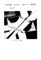
- FIG. 8 is a scanning-electron-microscope (SEM) photo of the micorstructure of a typical microbridge sensor.
- FIG. 9 is a partial schematic and block diagram of a circuit for use with sensor as depicted in FIG. 7(b) in accordance with the invention.
- FIG. 9a is a more detailed circuit schematic with reference to FIG. 7c.
- FIG. 10 is a schematic block diagram of the system of the invention including calibration and use functions.
- FIG. 11 us a scope trace representing the temperature signal rise versus time, for the configuration of FIG. 7(c) in response to a heater pulse for dry air at atmospheric pressure,
- FIG. 12 is a graphical representation of the temperature signal rise versus time, for the configuration of FIG. 7(c) in respnse to the heater pulse for various gases at atmospheric pressure as indicated.
- FIG. 13 is a graphical representation of thermal conductivity determination based on the bridge output of FIG. 9(a ).
- FIG. 14 is a theroetical graphical representation of sensor heat-up time versus pressure for several gases using the sensor configuration of FIG. 7b.
- FIG. 15 is similar to FIG. 14 based on data taken by a sensor of the type depicted in FIG. 7(b) calculated in accordance with the invention.
- FIG. 16 is a graphical representation of sensor heat-up time versus pressure for several gases using the sensor configuration of FIG. 7c.
- FIG. 17 is a graphical representation of sensor cooling time versus pressure for serveral gases using the sensor configuration of FIG. 7c.
- the present invention is directed to a system which enables both the determination of specific heat, c p , and thermal conductivity, k.
- the system utilizes a thermal pulse approach which is based on generating an energy or temperature pulse in a heater, which is coupled to a sensor primarily by the fluid medium (gas or liquid) of interest. Both quantities can be determined from a single pulse.
- specific temperatures are selected as "marker" points with respect to the sensor. These marker points are used to reference the determination of the time periods, as t 1 --t 2 , required to achieve the corresponding temperature rise(s) or fall(s) in the sensor(s) between the marker points.
- the sensor or sensors are located in predetermined spaced relation to the heater or heaters, but preferably physically separated therefrom so that the proximate influence of the solid heater material(s) is reduced and the coupling of the heater with the sensor or sensors by the fluid of interest is relatively enhanced.
- the preferred embodiments of the approach of the invention contemplate disposing spaced microscopic sized heating and sensing elements in a relatively static (zero flow) sample of the fluid of interest.
- the microsensor system or "microbridge” system as it will be referred to herein, though not limiting, is presently preferred for several reasons.
- the system is extremely fast reacting, is very accurate, very sensitive because of its advantageous coupling to the fluid of interest and small and adaptable to a variety of configurations.
- microbridge semiconductor chip sensor contemplated, for example, in certain embodiments preferred for the invention may resemble the form of one or more of the microbridge systems illustrated in the patents identified above. Such a system is exemplified by FIGS. 1-5 taken from Pat. No. 4,501,144. A discussion of that example will now be presented as it will be helpful in understanding the present invention. While the present discussion is believed sufficient, to the extent necessary, any additional material contained in the microbridge related patents cited is deemed to be incorporated herein by reference.
- FIGS. 1-5 contemplates a pair of thin film temperature sensors 22 and 24, a thin film heater 26 and a base 20 supporting the sensors and heater out of contact with the base. Sensors 22 and 24 are disposed on opposite sides of heater 26.
- Body 20 is a semiconductor, preferably silicon, chosen because of its adaptability to precision etching techniques and ease of electronic chip producibility.
- the embodiment includes two identical temperature sensing resistor grids 22 and 24 acting as the thin film heat sensors and a centrally located heater resistor grid 26 acting as the thin film heater.
- Sensors 22 and 24 and heater 26 may be fabricated of any suitable, stable metal or alloy film.
- the metal used was a nickel-iron alloy sometimes referred to as permalloy, with a composition of 80 percent nickel and 20 percent iron.
- the sensor and heater grids are encapsulated in a thin film of dielectric, typically comprising layers 28 and 29 and preferably silicon nitride, Si 3 N 4 , to form this film members.
- the sensor comprises two thin film members 32 and 34, member 32 comprising sensor 22 and 34 comprising sensor 24, each member comprising one-half of heater 26 and having a preferred dimension of 150 microns wide and 400 microns long.
- the embodiment of the system further describes an accurately defined air space 30 which contemplates air space effectively surrounding elements 22, 24, 26.
- the effectively surrounding air space is achieved by fabricating the structure on silicon surface 36, thin film elements 22, 24 and 26 having a preferred thickness of approximately 0.08 to 0.12 micron with lines on the order to 5 microns wide and spaces between lines on the order of 5 microns the elements encapsulated in a thin silicon nitride film preferably having a total thickness of approximately 0.8 microns or less, and by subsequently etching an accurately defined air space, of about 100 microns deep, into silicon body 20 beneath members 32 and 34.
- Members 32 and 34 connect to top surface 36 of semiconductor body 20 at one or more edges of depression or air space 30. As illustrated in FIG. 3, members 32 and 34 may be bridged across depression 30; alternately, for example, members 32 and 34 could be cantilevered over depression 30.
- the heater control circuit illustrated in FIGS. 4 uses a Wheatstone bridge 46 which further typically includes heater resistor 26 and a resistor 40 in its first leg and a resistor 42, heat sink resistor 38, and a resistor 44 in its second leg.
- An error integrator includes amplifiers 48 and 50 keeps bridge 46 balanced by varying the potential across it and thus the power dissipated in heater resistors 26.
- the circuitry of FIG. 5 monitors the resistance difference between downstream sensor 24 and upstream sensor 22.
- This circuitry includes a constant current source 52 comprising an amplifier 72 and a differential amplifier 54 further including amplifiers 68 and 70.
- the constant current source drives a Wheatstone bridge comprising two high impedance resistors 56 and 58 in one leg and the two sensing resistors 22 and 24 with a nulling potentiometer 60 in the other leg.
- the gain of differential amplifier 54 is adjusted by potentiometer 62.
- Output 64 provides an output voltage that is proportional to the resistance difference between the two sensing resistors 22 and 24.
- the power required by heater resistor to heat such a device 200° C., for example, above ambient temperature is less than 0.010 watt.
- FIGS. 7a, 7b, and 7c depict three slightly differing embodiments or configurations representative in terms of number and arrangement of the heaters and sensors which can be used in this invention.
- FIG. 7a in contrast to FIG. 1, all of the elements 122, 124 and 126 are used as heaters.
- FIG. 7b is an embodiment which is similar to the embodiment of FIG. 1 with thin film element 126 acting as heater and elements 122 and 124 acting as sensors.
- the embodiment of FIG. 7c represents the preferred arrangement in which the element 122 acts as heater and element 124 acts as sensor.
- the effective gap and thus the thermal isolation between heater and sensor is desirably wider in the embodiment of FIG. 7c.
- FIGS. 1-3, and 7a-7c The actual general geometric structure of the embodiments of FIGS. 1-3, and 7a-7c is more clearly illustrated in the scanning electron micrograph (SEM) photo to FIG. 8.
- SEM scanning electron micrograph
- the SEM represents a magnification such that the indicated length of 0.010" appears as shown.
- attention is directed to (1) setting specific temperature markers in the sensor to determine the time periods needed for achieving the corresponding temperature changes, (2) using temperature sensors which are physically separated from the heater so that the direct influence of the heater and heat conducted to the sensor other than via the fluid of interest is reduced, and (3) using a pulse which reaches at least a momentary steady-state plateau to determine k, which then is used with the transient measure to determine c p .
- FIG. 6 graphically depicts a square wave electrical energy pulse 130 to the heater as at 126 which results in quasi square wave heat pulses released by the heater. These in turn, result in reactive curves as at 131, 132 and 133 at the sensor which vary as described below.
- the pulse applied to the heater may have a height of about 4 volts with a pulse width of 100 ms. Since the heater is closely coupled through the fluid medium to the sensors, the family of curves 131, 132 and 133 resembles the shape of the input pulse. They show the heat response in the sensors 122 and 124.
- FIG. 11 represents an oscilloscope trace showing temperature rise and fall versus time for dry air at atmospheric pressure. The configuration is that of FIG.
- the heater 7b with a heater resistance of 800 ohms at room temperature, a heater pulse height of 2.5 volts and a heater pulse width of 100 ms. It uses a different scale for time than does FIG. 6, but illustrates the curve form produced by the pulsed input.
- the curves generally include beginning and ending transient portions flanking a relatively steady-state central portion. The relatively quick response of the sensor allows a relatively long steady-state to exist even with a pulse of 100 ms.
- the curves are affected by factors such as pressure and temperature as they influence the effective thermal conductivity and specific heat of the particular fluid of interest.
- Heat flowing from the heater element or elements to the sensor element or elements is conducted both through the fluid and through the solid semiconductor element support substrate or the like. It is advantageous with respect to the measurement of k or c p of the fluid of interest that the amount of heat reaching the sensor through the solid connections be minimized so that substantially all the measured thermal effect is generated via the fluid of interest.
- a is an exponential decay constant
- D T is the thermal diffusivity
- D T is related to k and c p by the expression
- D T may be a key to obtaining c p .
- the rise time constant, b was measured to be about 4 msec.
- D T ranges from 1.7 cm 2 /s for He to 0.054 cm 2 /s for C 3 H 8 .
- Metals exhibit high values such as 1.7, 1.1 and 0.18 cm 2 /s respectively for Ag, Cu and Fe. Insulators, however, are even lower than the gases at 0.004 cm 2 /s for glass and 0.0068 cm 2 for Si 3 N 4 which, as discussed above, is a good insulator.
- the effect is that the influence of the temperature wave propagating from one thin film strip, that is, the heater, to a second thin film strip, the sensor, both being embedded in a membrance of Si 3 N 4 , is faster for the gas than for the Si 3 N 4 .
- This also supports the choice of a material such as Si 3 N 4 , since it reduces the contribution of heat flow through the solid media. This is beneficial to the accuracy of the system.
- FIGS. 7a-7c Typical microbridge embodiments are illustrated by FIGS. 7a-7c. They will now be explained in greater detail.
- FIG. 7a involves using the same microresistance 122, 124, 126 for the heating pulse and the sensing task.
- the resistive heater-sensor element may be one leg of a conventional resistive Wheatstone bridge in a control circuit.
- FIG. 7b depicts an arrangement wherein the center microresistance structure 126 is used as a heater flanked by two symmetrically located outer sensing resistance elements 122 and 124.
- the elements 122 and 124 are separated from the heater 126 by a narrow gap.
- FIG. 7(c) shows an embodiment configuration in which the left element of the bridge 122 is used as the heating element and the right element 124 as the sensor. This embodiment takes advantage of a rather large central gap to achieve improved thermal isolation between the heater and the sensor.
- FIG. 9 shows a modified control circuit which uses the center microresistance 126 as heater, while the sensing task is performed by the two resistors 122 and 124.
- the dual heater sensor configuration corresponds to FIG. 7b and the circuit is representative of typical sensor/measurement circuit.
- FIG. 9 includes a timer 140 providing square-wave electrical pulses to the heater 126.
- the heater couples the heat pulse to the sensors 122 and 124 in the bridge 142.
- the output of the bridge is connected through an amplifier 143 to a pair of comparators 144 and 145 which operate "start” and "stop” inputs to a counter 146 which counts 10 mHz clock pulses.
- the counter counts measure the time interval (t 2 -t 1 ) between temperatures T 2 and T 1 illustrated in FIG. 6.
- FIG. 9a is similar to FIG. 9, but more detailed.
- the bridge configuration is the heater-space-sensor configuration of FIG. 7c.
- the sensor resistance arm of the microbridge is set into a Wheatstone bridge 150 at 124.
- Another proximate resistive arm 122 is fed a voltage pulse from pulse generator 151 to provide a heat pulse into the microbridge element 126.
- the Wheatstone bridge 150 also may contain a nulling balancing resistor 152 which can be used in the manner of potentiometer 60 in FIG. 5 to initially zero the device.
- the microbridge resistor sensor 124 in the Wheatstone bridge receives the heat pulse from heater element 122 principally by thermal conduction through the surrounding fluid. Some conduction, of course, does occur through the solid microbridge substrate and surroundings.
- the circuitry of FIG. 9a is conventional and can readily be explained with reference to its functional operation with regard to processing the bridge output signal.
- the voltage output signals of the bridge 150 are amplified by differential amplifiers 153 and 154 in a differential amplifier section.
- the imbalance signal is further amplified by a high gain amplifier at 155.
- the signal at 156 as is the case with the signal at 147 in FIG. 9 is in the form of a DC voltage signal, U, the amplitude of which is solely related to the thermal conductivity of the fluid of interest as will be discussed above.
- the remainder of the circuitry of FIG. 9a includes a DC level clamping amplifier 157 and isolation amplifier 158.
- the temperature level, time-related switching and counting circuitry includes comparators 159 and 160 together with Nand gates 161 and 162 having outputs which are connected to the counter timing device (not shown) as in FIG. 9.
- the timing device may be a conventional 10 MHz pulse counter or the like. Again, this is illustrated schematically in FIG. 6.
- the output signal from the Wheatstone bridge, U represents the voltage imbalance caused by the temperature change in microbridge sensor or sensors induced by the corresponding heater pulse output. Because the magnitude of this imbalance is related directly to the amount of energy absorbed by the sensor or sensors, the amplitude of the signal is directly related to the thermal conductivity, k, of the conducting media in a manner next explained.
- FIG. 6 shows that during much of the about 100 ms wide pulse period the temperature of the sensor reaches and maintains a constant value. During this time, the influence of the energy sink or source terms represented by specific heat are zero, which means that only thermal conductivity governs the value of the sensor temperature.
- FIG. 12 is a plot of temperature rise in the form of bridge output, U, (FIG. 9 or 9a) using the sensing arrangement of FIG. 7(b) versus time in milliseconds for various gases at atmospheric pressure. Curves for methane, dry air, ethane and a vacuum are presented. In this specific embodiment there was a heater resistance of 800 ohms, a pulse height of 2.5 volts, and a pulse width of 100 ms. Temperature markers t, and t 2 are shown on the graph. These markers relate to those of FIG. 13 which shows a graphical presentation of heat up time versus pressure for several gases with a sensor-heater such as that shown in FIG. 7b and using the T 2 -T 1 , marked in FIG. 11.
- This determination requrires that the measuring system be calibrated first, which consists of determining the coefficients a 1 , a 2 , and a 3 , of the algorithm to then compute c p .
- the measured sensor temperature response may be described with reference to the following processes (at zero gas flow):
- T h -T o Q/(k s A s /L s +k g A g /L g ) with Q in watts; the temperature T h is established in a time that is short compared to the time it takes to reach the sensor if the sensor is not identical to the heater, as in configurations 7(b) and 7(c).
- the sensor temperature rise rate is governed by the specific heat of the gas surrounding the sensor and the closely coupled material of the sensor itself so that:
- FIGS. 14, 15 and 16 The quantity measured and plotted in FIGS. 14, 15 and 16, is the time (dt) needed to raise the sensor temperature by an increment (dT) which is chosen by the two or more sensor resistance value markers corresponding to T 1 and T 2 .
- FIG. 14 and FIG. 15 are for configuration 7b with a pulse height of 2.5 volts and a pulse width of 100 ms.
- FIG. 16 is for configuration 7c with a pulse height of 1.75 v. and a pulse width of 100 ms.
- gases of known composition preferably but not necessarily pure
- gases of known composition preferably but not necessarily pure
- specific heat and thermal conductivity both also measured
- the effect of the pulsed heat releases is recorded in terms of the lapsed time, t 2 -t 1 , as has been described.
- MLRA multiple linear regression analysis
- FIG. 15 Proof that the above calibration coefficients are valid is provided by FIG. 15, for example, in which these coefficients have been used to generate the shown lines for CH 4 , C 2 H 6 , air and O 2 . As shown, the lines indeed connect and agree with all experimental points. Additional lines have been plotted with the c p and k data of the literature for other gases as well.
- the final step in using this calibration method involves known means to store, write or burn in the obtained, tailored values of a 1 , a 2 and a 3 for the individual microbridge, which may be a Honeywell MICRO-SWITCH Model No. AWM-2100V, into the memory linked to it.
- the microsensor is then ready for use to measure the specific heat of unknown gases, provided that P and k be known at the time of measurement.
- FIG. 10 depicts a schematic block diagram of a device for measuring c p and k.
- the system includes the signal processing circuitry indicated by 170, a multiple linear regression analysis (MLRA) unit 171 for deriving the known equation constants for the particular microbridge configuration and circuitry used, i.e., a 1 -a n , a data bank 172 for storing calibration c p and k data and an output interface unit 173.
- MLRA multiple linear regression analysis
- field recalibration may be accomplished simply by entering the P, c p and k values of the test gas into the data bank.
- P cannot be measured independently of the sensor already in the subject system its errors can be incorporated as a correction in the c p and k recalibration.
- the measured values of U and dt are then used as in the measurement mode to determine sensor values of k and c p . If they disagree from the entered values the constants a 3 and a 5 may be modified to fit the entered or book values.
- This approach may be a practical one for field use, but it should be checked by using a second test gas. If that agrees, the recalibration may be completed. If not, a complete calibration of all a 1 -a 5 coefficients should be made.
- FIG. 16 depicts heating time in milliseconds versus pressure and gas type and specifically showing curves for methane, ethane, air and oxygen.
- the sensing configuration of FIG. 7(c) was used.
- the pulse height was 1.75 volts with a pulse width of 100 ms. and the heater and sensor resistance each being about 2000 ohms.
- FIG. 17 depicts a cooling curve for the same configuration as FIG. 16.
- FIG. 17 is a plot of the cooling time vs. pressure for different types of gas. Conditions were the same except that the pulse height was 4.0 volts.
- the output of the device can be in any desired form including analog or digital signals, printed records, etc., after the value is obtained.
Landscapes
- General Health & Medical Sciences (AREA)
- Health & Medical Sciences (AREA)
- Life Sciences & Earth Sciences (AREA)
- Chemical & Material Sciences (AREA)
- Analytical Chemistry (AREA)
- Biochemistry (AREA)
- Physics & Mathematics (AREA)
- General Physics & Mathematics (AREA)
- Immunology (AREA)
- Pathology (AREA)
- Investigating Or Analyzing Materials Using Thermal Means (AREA)
- Compositions Of Macromolecular Compounds (AREA)
- Resistance Heating (AREA)
Priority Applications (7)
| Application Number | Priority Date | Filing Date | Title |
|---|---|---|---|
| US07/210,892 US4944035A (en) | 1988-06-24 | 1988-06-24 | Measurement of thermal conductivity and specific heat |
| JP1146525A JP2797198B2 (ja) | 1988-06-24 | 1989-06-08 | 流体の熱伝導率及び比熱測定方法及び装置 |
| CA000603302A CA1336621C (en) | 1988-06-24 | 1989-06-20 | Measurement of thermal conductivity and specific heat |
| DK312389A DK312389A (da) | 1988-06-24 | 1989-06-23 | Fremgangsmaade og apparat til bestemmelse af den termiske konduktivitet og specifikke varme af et fluid |
| DE68927242T DE68927242T2 (de) | 1988-06-24 | 1989-06-26 | Messung von Wärmeleitung und spezifischer Wärme |
| EP89306456A EP0348245B1 (en) | 1988-06-24 | 1989-06-26 | Measurement of thermal conductivity and specific heat |
| AT89306456T ATE143494T1 (de) | 1988-06-24 | 1989-06-26 | Messung von wärmeleitung und spezifischer wärme |
Applications Claiming Priority (1)
| Application Number | Priority Date | Filing Date | Title |
|---|---|---|---|
| US07/210,892 US4944035A (en) | 1988-06-24 | 1988-06-24 | Measurement of thermal conductivity and specific heat |
Publications (1)
| Publication Number | Publication Date |
|---|---|
| US4944035A true US4944035A (en) | 1990-07-24 |
Family
ID=22784724
Family Applications (1)
| Application Number | Title | Priority Date | Filing Date |
|---|---|---|---|
| US07/210,892 Expired - Lifetime US4944035A (en) | 1988-06-24 | 1988-06-24 | Measurement of thermal conductivity and specific heat |
Country Status (7)
| Country | Link |
|---|---|
| US (1) | US4944035A (da) |
| EP (1) | EP0348245B1 (da) |
| JP (1) | JP2797198B2 (da) |
| AT (1) | ATE143494T1 (da) |
| CA (1) | CA1336621C (da) |
| DE (1) | DE68927242T2 (da) |
| DK (1) | DK312389A (da) |
Cited By (131)
| Publication number | Priority date | Publication date | Assignee | Title |
|---|---|---|---|---|
| US5059032A (en) * | 1990-08-16 | 1991-10-22 | The Dow Chemical Company | Free standing fluxmeter fixture with dual infrared pyrometers |
| US5163754A (en) * | 1989-08-08 | 1992-11-17 | The United States Of America As Represented By The United States Department Of Energy | Isolated thermocouple amplifier system for stirred fixed-bed gasifier |
| US5177696A (en) * | 1989-12-28 | 1993-01-05 | Honeywell Inc. | Method of determination of gas properties at reference conditions |
| US5176358A (en) * | 1991-08-08 | 1993-01-05 | Honeywell Inc. | Microstructure gas valve control |
| US5187674A (en) * | 1989-12-28 | 1993-02-16 | Honeywell Inc. | Versatile, overpressure proof, absolute pressure sensor |
| WO1993008457A1 (en) * | 1991-10-23 | 1993-04-29 | Niagara Mohawk Power Corporation | On-line combustionless measurement of gaseous fuels fed to gas consumption devices |
| US5235844A (en) * | 1991-10-23 | 1993-08-17 | Niagara Mohawk Power Corporation | Multiple gas property sensor |
| US5237523A (en) * | 1990-07-25 | 1993-08-17 | Honeywell Inc. | Flowmeter fluid composition and temperature correction |
| US5297419A (en) * | 1992-07-16 | 1994-03-29 | Thermco Instrument Corporation | Linearizing gas analyzer |
| US5303167A (en) * | 1991-03-08 | 1994-04-12 | Honeywell Inc. | Absolute pressure sensor and method |
| US5436165A (en) * | 1990-04-17 | 1995-07-25 | Brenner; Alan | Reaction control and solids characterization device |
| US5441597A (en) * | 1992-12-01 | 1995-08-15 | Honeywell Inc. | Microstructure gas valve control forming method |
| US5461910A (en) * | 1994-06-16 | 1995-10-31 | Alnor Instrument Company | Fluid flow direction and velocity monitor |
| US5486107A (en) * | 1992-01-30 | 1996-01-23 | Honeywell, Inc. | Determination of fuel characteristics |
| US5490184A (en) * | 1994-07-21 | 1996-02-06 | Westinghouse Electric Corporation | Method and a system for accurately calculating PWR power from excore detector currents corrected for changes in 3-D power distribution and coolant density |
| US5515295A (en) * | 1990-11-09 | 1996-05-07 | Hewlett-Packard Company | Methods and systems for fluid identification and flow rate determination |
| US5535614A (en) * | 1993-11-11 | 1996-07-16 | Nok Corporation | Thermal conductivity gas sensor for measuring fuel vapor content |
| US5756878A (en) * | 1995-01-24 | 1998-05-26 | Yamatake-Honeywell Co., Ltd. | Thermal conductivity measuring device |
| WO1999034201A1 (en) * | 1997-12-31 | 1999-07-08 | Honeywell Inc. | Time lag approach for measuring thermal conductivity and specific heat |
| WO1999034200A1 (en) * | 1997-12-31 | 1999-07-08 | Honeywell Inc. | Method and apparatus for measuring selected properties of a fluid of interest using a single heater element |
| WO1999034198A3 (en) * | 1997-12-31 | 1999-09-10 | Honeywell Inc | Fluid property and flow sensing via a common frequency generator and fast fourier transformation |
| US6132083A (en) * | 1994-11-02 | 2000-10-17 | Aboatech Ltd. | Real-time measuring method |
| US6223593B1 (en) | 1997-12-31 | 2001-05-01 | Honeywell International Inc. | Self-oscillating fluid sensor |
| US6234016B1 (en) | 1997-12-31 | 2001-05-22 | Honeywell International Inc. | Time lag approach for measuring fluid velocity |
| US6241383B1 (en) * | 1998-03-25 | 2001-06-05 | Murray F. Feller | Heat exchanger maintenance monitor apparatus and method |
| US6289719B1 (en) * | 1997-10-02 | 2001-09-18 | Robert Bosch Gmbh | Method for operating a gas sensor |
| US6331075B1 (en) | 1998-05-01 | 2001-12-18 | Administrator, National Aeronautics And Space Administration | Device and method for measuring thermal conductivity of thin films |
| US6393894B1 (en) | 1999-07-27 | 2002-05-28 | Honeywell International Inc. | Gas sensor with phased heaters for increased sensitivity |
| US20020147506A1 (en) * | 2001-03-01 | 2002-10-10 | Evren Eryurek | Fiducial technique for estimating and using degradation levels in a process plant |
| US20020147511A1 (en) * | 2001-03-01 | 2002-10-10 | Evren Eryurek | Enhanced hart device alerts in a process control system |
| US6474138B1 (en) | 2000-11-28 | 2002-11-05 | Honeywell International Inc. | Adsorption based carbon monoxide sensor and method |
| US6502459B1 (en) | 2000-09-01 | 2003-01-07 | Honeywell International Inc. | Microsensor for measuring velocity and angular direction of an incoming air stream |
| US20030014500A1 (en) * | 2001-07-10 | 2003-01-16 | Schleiss Trevor D. | Transactional data communications for process control systems |
| US6550310B1 (en) | 2000-11-28 | 2003-04-22 | Honeywell International Inc. | Catalytic adsorption and oxidation based carbon monoxide sensor and detection method |
| US20030119197A1 (en) * | 2001-12-20 | 2003-06-26 | Ulrich Bonne | Fluid mixture composition sensor |
| US6609412B2 (en) | 2001-03-22 | 2003-08-26 | University Of Maryland | Sensor probe for measuring temperature and liquid volumetric fraction of a liquid droplet laden hot gas and method of using same |
| US6662121B1 (en) * | 1999-04-27 | 2003-12-09 | Yazaki Corporation | Thermal fluid sensor, fluid discriminating apparatus and method, flow sensor, and flow rate measuring apparatus and method |
| US20030235925A1 (en) * | 2002-06-14 | 2003-12-25 | Ulrich Bonne | Flammable vapor sensor |
| WO2004038400A2 (en) | 2002-09-27 | 2004-05-06 | Honeywell International Inc. | Phased sensor system with multiple parallel preconcentrators |
| US20040111499A1 (en) * | 2002-12-10 | 2004-06-10 | Dobrowski Patrick M. | Method for launching applications |
| US20040107766A1 (en) * | 2002-12-05 | 2004-06-10 | Honeywell International Inc. | Health monitor |
| US20040129057A1 (en) * | 2002-09-27 | 2004-07-08 | Ulrich Bonne | Phased micro analyzer II, IIA |
| US20040136437A1 (en) * | 2003-01-14 | 2004-07-15 | Satya Prakash | Thermal characterization chip |
| US20040158474A1 (en) * | 2003-02-06 | 2004-08-12 | Karschnia Robert J. | Service facility for providing remote diagnostic and maintenance services to a process plant |
| US20040172147A1 (en) * | 2003-02-28 | 2004-09-02 | Fisher-Rosemount Systems Inc. | Delivery of process plant notifications |
| US20040181364A1 (en) * | 2003-03-13 | 2004-09-16 | Csi Technology, Inc. | Generation of data indicative of machine operational condition |
| US6795798B2 (en) | 2001-03-01 | 2004-09-21 | Fisher-Rosemount Systems, Inc. | Remote analysis of process control plant data |
| US6792794B2 (en) | 2002-09-27 | 2004-09-21 | Honeywell International Inc. | Low power gas leak detector |
| US20040186927A1 (en) * | 2003-03-18 | 2004-09-23 | Evren Eryurek | Asset optimization reporting in a process plant |
| US20040223882A1 (en) * | 2002-09-27 | 2004-11-11 | Ulrich Bonne | Micro-plasma sensor system |
| US20040224422A1 (en) * | 2002-09-27 | 2004-11-11 | Ulrich Bonne | Phased micro analyzer III, IIIA |
| WO2004029602A3 (en) * | 2002-09-27 | 2004-11-18 | Honeywell Int Inc | Phased micro analyser |
| US20040230328A1 (en) * | 2003-03-21 | 2004-11-18 | Steve Armstrong | Remote data visualization within an asset data system for a process plant |
| US20040255057A1 (en) * | 2003-06-16 | 2004-12-16 | Greg Opheim | Method and apparatus for providing help information in multiple formats |
| US20040259265A1 (en) * | 2002-09-27 | 2004-12-23 | Ulrich Bonne | Phased micro analyzer IV |
| US20050028580A1 (en) * | 2001-09-20 | 2005-02-10 | Michael Bauer | Sensor module having a sensor element surrounded by a heating element |
| US20050063865A1 (en) * | 2002-09-27 | 2005-03-24 | Ulrich Bonne | Phased VII micro fluid analyzer having a modular structure |
| US20050142035A1 (en) * | 2003-12-31 | 2005-06-30 | Ulrich Bonne | Micro-discharge sensor system |
| US20050141999A1 (en) * | 2003-12-31 | 2005-06-30 | Ulrich Bonne | Micro ion pump |
| US20050190054A1 (en) * | 2004-02-26 | 2005-09-01 | Cindy Scott | Method and system for integrated alarms in a process control system |
| US20050197806A1 (en) * | 2004-03-03 | 2005-09-08 | Fisher-Rosemount Systems, Inc. | Configuration system and method for abnormal situation prevention in a process plant |
| US20050197803A1 (en) * | 2004-03-03 | 2005-09-08 | Fisher-Rosemount Systems, Inc. | Abnormal situation prevention in a process plant |
| US20050197805A1 (en) * | 2001-03-01 | 2005-09-08 | Fisher-Rosemount Systems, Inc. | Data presentation system for abnormal situation prevention in a process plant |
| US20050222698A1 (en) * | 2004-03-30 | 2005-10-06 | Fisher-Rosemount Systems, Inc. | Integrated configuration system for use in a process plant |
| US6954713B2 (en) | 2001-03-01 | 2005-10-11 | Fisher-Rosemount Systems, Inc. | Cavitation detection in a process plant |
| US20050259714A1 (en) * | 2004-05-20 | 2005-11-24 | Yuli Lozinski | System for measuring heat flow |
| US20050267709A1 (en) * | 2004-05-28 | 2005-12-01 | Fisher-Rosemount Systems, Inc. | System and method for detecting an abnormal situation associated with a heater |
| US20050267710A1 (en) * | 2004-05-28 | 2005-12-01 | Fisher-Rosemount Systems, Inc. | System and method for detecting an abnormal situation associated with a heater |
| US20060020423A1 (en) * | 2004-06-12 | 2006-01-26 | Fisher-Rosemount Systems, Inc. | System and method for detecting an abnormal situation associated with a process gain of a control loop |
| US20060064182A1 (en) * | 2004-09-17 | 2006-03-23 | Fisher-Rosemount Systems, Inc. | System and method for detecting an abnormal situation associated with a reactor |
| DE19535819B4 (de) * | 1995-09-26 | 2006-06-08 | Wagner, Gerhard R., Dipl.-Ing. | Verfahren zur Ermittlung eines bestimmten Merkmals einer brennbaren Gasmischung |
| US20060262303A1 (en) * | 2005-05-17 | 2006-11-23 | Honeywell International Inc. | An optical micro-spectrometer |
| US7152072B2 (en) | 2003-01-08 | 2006-12-19 | Fisher-Rosemount Systems Inc. | Methods and apparatus for importing device data into a database system used in a process plant |
| US20070028670A1 (en) * | 2005-05-17 | 2007-02-08 | Honeywell International Inc. | Three-wafer channel structure for a fluid analyzer |
| US7206646B2 (en) | 1999-02-22 | 2007-04-17 | Fisher-Rosemount Systems, Inc. | Method and apparatus for performing a function in a plant using process performance monitoring with process equipment monitoring and control |
| US20070148039A1 (en) * | 2005-12-27 | 2007-06-28 | Honeywell International Inc. | Fluid sensing and control in a fluidic analyzer |
| US7246939B1 (en) | 2003-10-23 | 2007-07-24 | Gultekin David H | Measurement of thermal diffusivity, thermal conductivity, specific heat, specific absorption rate, thermal power, heat transfer coefficient, heat of reaction and membrane permeability by nuclear magnetic resonance |
| US7272531B2 (en) | 2005-09-20 | 2007-09-18 | Fisher-Rosemount Systems, Inc. | Aggregation of asset use indices within a process plant |
| US20070223558A1 (en) * | 2006-03-21 | 2007-09-27 | Martin Lopez | Thermal conductivity sensor |
| US20080025365A1 (en) * | 2004-05-21 | 2008-01-31 | Kyoto Electronics Manufacturing Co., Ltd. | Specific Heat Measuring Method and Instrument |
| US20080027678A1 (en) * | 2006-07-25 | 2008-01-31 | Fisher-Rosemount Systems, Inc. | Method and system for detecting abnormal operation in a process plant |
| US20080027677A1 (en) * | 2006-07-25 | 2008-01-31 | Fisher-Rosemount Systems, Inc. | Methods and systems for detecting deviation of a process variable from expected values |
| US7346404B2 (en) | 2001-03-01 | 2008-03-18 | Fisher-Rosemount Systems, Inc. | Data sharing in a process plant |
| US20080101434A1 (en) * | 2001-07-16 | 2008-05-01 | Horovitz Michael L | Sensor device and method for qualitative and quantitative analysis of gas phase substances |
| US20080125879A1 (en) * | 2006-07-25 | 2008-05-29 | Fisher-Rosemount Systems, Inc. | Method and system for detecting abnormal operation of a level regulatory control loop |
| US20080183427A1 (en) * | 2007-01-31 | 2008-07-31 | Fisher-Rosemount Systems, Inc. | Heat Exchanger Fouling Detection |
| US20080188972A1 (en) * | 2006-10-11 | 2008-08-07 | Fisher-Rosemount Systems, Inc. | Method and System for Detecting Faults in a Process Plant |
| US20080288321A1 (en) * | 2007-05-15 | 2008-11-20 | Fisher-Rosemount Systems, Inc. | Automatic maintenance estimation in a plant environment |
| US7493310B2 (en) | 2002-12-30 | 2009-02-17 | Fisher-Rosemount Systems, Inc. | Data visualization within an integrated asset data system for a process plant |
| US20090100906A1 (en) * | 2002-09-27 | 2009-04-23 | Honeywell International Inc. | Phased micro analyzer viii |
| US7557702B2 (en) | 1999-02-22 | 2009-07-07 | Evren Eryurek | Integrated alert generation in a process plant |
| US7562135B2 (en) | 2000-05-23 | 2009-07-14 | Fisher-Rosemount Systems, Inc. | Enhanced fieldbus device alerts in a process control system |
| US20090277246A1 (en) * | 2005-09-27 | 2009-11-12 | Yamatake Corporation | Thermal conductivity measuring method and apparatus, and gas component ratio measuring apparatus |
| US7702401B2 (en) | 2007-09-05 | 2010-04-20 | Fisher-Rosemount Systems, Inc. | System for preserving and displaying process control data associated with an abnormal situation |
| US20100101301A1 (en) * | 2008-10-28 | 2010-04-29 | Honeywell International Inc. | Gas pulse generator for baseline drift correction and related system and method |
| US7853431B2 (en) | 2006-09-29 | 2010-12-14 | Fisher-Rosemount Systems, Inc. | On-line monitoring and diagnostics of a process using multivariate statistical analysis |
| US7953842B2 (en) | 2003-02-19 | 2011-05-31 | Fisher-Rosemount Systems, Inc. | Open network-based data acquisition, aggregation and optimization for use with process control systems |
| US8005647B2 (en) | 2005-04-08 | 2011-08-23 | Rosemount, Inc. | Method and apparatus for monitoring and performing corrective measures in a process plant using monitoring data with corrective measures data |
| US8032341B2 (en) | 2007-01-04 | 2011-10-04 | Fisher-Rosemount Systems, Inc. | Modeling a process using a composite model comprising a plurality of regression models |
| US8032340B2 (en) | 2007-01-04 | 2011-10-04 | Fisher-Rosemount Systems, Inc. | Method and system for modeling a process variable in a process plant |
| US8042994B1 (en) * | 2010-11-08 | 2011-10-25 | Murray F Feller | Specific heat meter with improved accuracy |
| US8055479B2 (en) | 2007-10-10 | 2011-11-08 | Fisher-Rosemount Systems, Inc. | Simplified algorithm for abnormal situation prevention in load following applications including plugged line diagnostics in a dynamic process |
| US8073967B2 (en) | 2002-04-15 | 2011-12-06 | Fisher-Rosemount Systems, Inc. | Web services-based communications for use with process control systems |
| US8301676B2 (en) | 2007-08-23 | 2012-10-30 | Fisher-Rosemount Systems, Inc. | Field device with capability of calculating digital filter coefficients |
| US8417595B2 (en) | 2001-03-01 | 2013-04-09 | Fisher-Rosemount Systems, Inc. | Economic calculations in a process control system |
| WO2013075111A1 (en) * | 2011-11-17 | 2013-05-23 | Utah State University | Thermal pulse flow meter |
| US8606544B2 (en) | 2006-07-25 | 2013-12-10 | Fisher-Rosemount Systems, Inc. | Methods and systems for detecting deviation of a process variable from expected values |
| US8762106B2 (en) | 2006-09-28 | 2014-06-24 | Fisher-Rosemount Systems, Inc. | Abnormal situation prevention in a heat exchanger |
| EP2733334A4 (en) * | 2011-07-13 | 2014-12-24 | Toyota Motor Co Ltd | CONTROL DEVICE FOR A COMBUSTION ENGINE |
| US8935298B2 (en) | 2002-12-30 | 2015-01-13 | Fisher-Rosemount Systems, Inc. | Integrated navigational tree importation and generation in a process plant |
| US9029028B2 (en) | 2003-12-29 | 2015-05-12 | Honeywell International Inc. | Hydrogen and electrical power generator |
| EP2677283A4 (en) * | 2011-02-18 | 2015-05-20 | Tohoku Gakuin | THERMALLY CONDUCTIVE SENSOR UNPERTURBED BY TEMPERATURE AND TYPE OF FLUID WHICH CROSSES SAME, AND THERMAL FLOW SENSOR AND BAROMETRIC THERMAL SENSOR COMPRISING THERMALLY CONDUCTING SENSOR |
| US9201420B2 (en) | 2005-04-08 | 2015-12-01 | Rosemount, Inc. | Method and apparatus for performing a function in a process plant using monitoring data with criticality evaluation data |
| US9267907B2 (en) | 2011-01-20 | 2016-02-23 | Siemens Aktiengesellschaft | Measurement arrangement having electrically heated resistors arranged in gas paths |
| US9323247B2 (en) | 2007-09-14 | 2016-04-26 | Fisher-Rosemount Systems, Inc. | Personalized plant asset data representation and search system |
| US9529348B2 (en) | 2012-01-24 | 2016-12-27 | Emerson Process Management Power & Water Solutions, Inc. | Method and apparatus for deploying industrial plant simulators using cloud computing technologies |
| US9791595B2 (en) | 2014-03-10 | 2017-10-17 | Halliburton Energy Services Inc. | Identification of heat capacity properties of formation fluid |
| US9790782B2 (en) | 2014-03-10 | 2017-10-17 | Halliburton Energy Services Inc. | Identification of thermal conductivity properties of formation fluid |
| US9927788B2 (en) | 2011-05-19 | 2018-03-27 | Fisher-Rosemount Systems, Inc. | Software lockout coordination between a process control system and an asset management system |
| US20180120245A1 (en) * | 2016-10-29 | 2018-05-03 | Sendsor Gmbh | Sensor and Method for Measuring Respiratory Gas Properties |
| EP3348969A1 (en) | 2017-01-12 | 2018-07-18 | Sensirion AG | Measurement of a fluid parameter and sensor device therefore |
| EP3421947A1 (en) | 2017-06-30 | 2019-01-02 | Sensirion AG | Operation method for flow sensor device |
| WO2019185181A1 (en) | 2018-10-05 | 2019-10-03 | Sensirion Ag | Device for regulating a mixing ratio of a gas mixture |
| CN110346408A (zh) * | 2019-06-24 | 2019-10-18 | 金华职业技术学院 | 一种生物样品的热量测试方法 |
| US10724976B2 (en) | 2016-08-18 | 2020-07-28 | Nevada Nanotech Systems Inc. | Systems and methods for determining at least one property of a material |
| US20210116281A1 (en) * | 2019-10-21 | 2021-04-22 | Flusso Limited | Thermal Fluid Flow Sensor |
| US11169103B2 (en) | 2018-10-19 | 2021-11-09 | Diehl Metering Gmbh | Thermal gas sensor, method for measuring the thermal diffusivity of a gas or gas mixture and method for measuring the thermal conductivity of a gas or gas mixture |
| US11340182B2 (en) | 2016-10-29 | 2022-05-24 | Idiag Ag | Breathing apparatus |
| EP4009008A1 (en) | 2020-12-03 | 2022-06-08 | Sensirion AG | Fault detection in a thermal sensor device |
| US11385086B2 (en) | 2018-07-06 | 2022-07-12 | Becton, Dickinson And Company | Flow sensor and method for adjusting fluid flow measurement |
| WO2022268892A3 (en) * | 2021-06-22 | 2023-02-02 | Flusso Limited | Thermal fluid sensor |
Families Citing this family (15)
| Publication number | Priority date | Publication date | Assignee | Title |
|---|---|---|---|---|
| WO1991006809A1 (en) * | 1989-10-30 | 1991-05-16 | Honeywell Inc. | Microbridge-based combustion control |
| JP2579265B2 (ja) * | 1992-06-22 | 1997-02-05 | 雪印乳業株式会社 | 流体の熱伝導率の測定方法及び流体の状態の測定装置 |
| EP1111377A1 (de) * | 1999-12-23 | 2001-06-27 | Fraunhofer-Gesellschaft Zur Förderung Der Angewandten Forschung E.V. | Verfahren und Vorrichtung zur Bestimmung der Konzentration eines Stoffes in einem Flüssigkeitsvolumen |
| US6612269B2 (en) | 2000-08-11 | 2003-09-02 | The Regents Of The University Of California | Apparatus and method for operating internal combustion engines from variable mixtures of gaseous fuels |
| ATE355510T1 (de) * | 2001-01-30 | 2006-03-15 | Ems Patent Ag | Gaszähler |
| DE10206275B4 (de) * | 2002-02-15 | 2007-01-04 | Bundesrepublik Deutschland, vertr. d. d. Bundesministerium für Wirtschaft und Technologie, dieses vertr. d. d. Präsidenten der Physikalisch-Technischen Bundesanstalt | Verfahren zur Messung der Temperaturleitfähigkeit |
| JP2006515667A (ja) * | 2002-09-27 | 2006-06-01 | ハネウェル・インターナショナル・インコーポレーテッド | 位相マイクロ型分析器 |
| US7003418B2 (en) * | 2003-08-28 | 2006-02-21 | Honeywell International Inc. | Methods and systems for temperature compensation of physical property sensors |
| ES2284296B1 (es) * | 2004-03-16 | 2008-09-16 | Naturcorp Multiservicios, S.A. | Metodo para la determinacion del numero de metano de gases combustibles. |
| DE102004022206B4 (de) * | 2004-05-04 | 2006-05-11 | Bundesrepublik Deutschland, vertr. d. d. Bundesministerium für Wirtschaft und Arbeit, dieses vertr. d. d. Präsidenten der Physikalisch-Technischen Bundesanstalt | Sensor und Sensoranordnung zur Messung der Wärmeleitfähigkeit einer Probe |
| DE102007015609A1 (de) * | 2007-03-29 | 2008-10-09 | Hydrometer Gmbh | Kälte- oder Wärmezählereinrichtung zur Ermittlung des Energieverbrauchs in einem Temperierungskreislauf |
| JP5165627B2 (ja) * | 2009-03-30 | 2013-03-21 | アズビル株式会社 | 物性値測定システム及び物性値測定方法 |
| DE102013006397B4 (de) | 2012-05-22 | 2023-06-29 | Abb Schweiz Ag | Thermischer Durchflussmesser und Verfahren zum Betrieb desselben |
| EP3367087A3 (en) * | 2018-04-30 | 2018-12-26 | Sensirion AG | Sensor for determining thermal capacity of fluids |
| JP6728509B1 (ja) * | 2020-03-05 | 2020-07-22 | 日本たばこ産業株式会社 | エアロゾル吸引器の電源ユニット |
Citations (24)
| Publication number | Priority date | Publication date | Assignee | Title |
|---|---|---|---|---|
| US3672205A (en) * | 1970-12-14 | 1972-06-27 | Us Air Force | Determination of heat transfer through fluids |
| US3821895A (en) * | 1971-09-29 | 1974-07-02 | Showa Denko Kk | Heat flow meter for remote measurement |
| US3913379A (en) * | 1973-10-18 | 1975-10-21 | Tibor Rusz | Dynamic gas analyzer |
| US4036051A (en) * | 1974-10-08 | 1977-07-19 | Roger Fell | Heat meters |
| US4063447A (en) * | 1977-03-14 | 1977-12-20 | Honeywell, Inc. | Bridge circuit with drift compensation |
| US4123934A (en) * | 1976-06-22 | 1978-11-07 | Auergesellschaft Gmbh | Bridge circuit arrangement for a gas detection instrument |
| US4164862A (en) * | 1977-11-25 | 1979-08-21 | Jackson Milton L | Multicomponent thermal conductivity analyzer |
| US4254654A (en) * | 1976-10-07 | 1981-03-10 | Hewlett-Packard Company | Modulated fluid detector |
| US4381154A (en) * | 1980-09-26 | 1983-04-26 | The Hetra Corporation | Method of and apparatus for nondestructively determining the composition of an unknown material sample |
| US4461166A (en) * | 1982-02-26 | 1984-07-24 | Delta Associates, Inc. | Dynamic current drive method for powering thermal conductivity detectors |
| US4478077A (en) * | 1982-09-30 | 1984-10-23 | Honeywell Inc. | Flow sensor |
| US4478076A (en) * | 1982-09-30 | 1984-10-23 | Honeywell Inc. | Flow sensor |
| US4501144A (en) * | 1982-09-30 | 1985-02-26 | Honeywell Inc. | Flow sensor |
| US4594879A (en) * | 1982-10-28 | 1986-06-17 | Yokogawa Hokushin Electric Corporation | Thermal conductivity detector |
| US4630938A (en) * | 1983-04-27 | 1986-12-23 | Polska Akademia Nauk Centrum Badan Molekularnych I Makromolekularnych | Method of determination of thermal conduction coefficient and heat capacity of materials and the apparatus for measurements of thermal conduction coefficient and heat capacity of material |
| US4651564A (en) * | 1982-09-30 | 1987-03-24 | Honeywell Inc. | Semiconductor device |
| US4683159A (en) * | 1982-09-30 | 1987-07-28 | Honeywell Inc. | Semiconductor device structure and processing |
| US4697165A (en) * | 1984-11-01 | 1987-09-29 | Ngk Insulators, Ltd. | Ceramic heater and a method of manufacturing the same |
| US4734641A (en) * | 1987-03-09 | 1988-03-29 | Tektronix, Inc. | Method for the thermal characterization of semiconductor packaging systems |
| US4735082A (en) * | 1986-07-14 | 1988-04-05 | Hewlett-Packard Company | Pulse modulated thermal conductivity detector |
| US4739657A (en) * | 1987-06-22 | 1988-04-26 | Honeywell Inc. | Resistance with linear temperature coefficient |
| US4741198A (en) * | 1986-10-06 | 1988-05-03 | Beckman Industrial Corporation | Thermal conductivity detector assembly |
| US4783996A (en) * | 1985-02-02 | 1988-11-15 | Nippon Soken, Inc. | Direct-heated flow measuring apparatus |
| US4825693A (en) * | 1982-09-30 | 1989-05-02 | Honeywell Inc. | Slotted diaphragm semiconductor device |
Family Cites Families (6)
| Publication number | Priority date | Publication date | Assignee | Title |
|---|---|---|---|---|
| US451144A (en) * | 1891-04-28 | vincent | ||
| DE2513342C2 (de) * | 1975-03-26 | 1986-12-11 | Wolfgang 6090 Rüsselsheim Borkowetz | Verfahren und Vorrichtung zur Bestimmung der Wärmeleitfähigkeit und der spezifischen Wärme |
| DE2701774A1 (de) * | 1977-01-18 | 1978-07-20 | D I Wolfgang Borkowetz | Sonde zur absoluten bestimmung der waermeleitfaehigkeit und der spezifischen waerme |
| EP0070801A1 (fr) * | 1981-07-13 | 1983-01-26 | Battelle Memorial Institute | Procédé pour déterminer au moins un paramètre instantané d'un fluide lié à l'échange thermique d'une sonde immergée dans ce fluide et dispositif pour la mise en oeuvre de ce procédé |
| JPS62170844A (ja) * | 1986-01-24 | 1987-07-27 | Sord Comput Corp | 熱伝導度検出器用発熱器 |
| US4706061A (en) * | 1986-08-28 | 1987-11-10 | Honeywell Inc. | Composition sensor with minimal non-linear thermal gradients |
-
1988
- 1988-06-24 US US07/210,892 patent/US4944035A/en not_active Expired - Lifetime
-
1989
- 1989-06-08 JP JP1146525A patent/JP2797198B2/ja not_active Expired - Fee Related
- 1989-06-20 CA CA000603302A patent/CA1336621C/en not_active Expired - Fee Related
- 1989-06-23 DK DK312389A patent/DK312389A/da not_active Application Discontinuation
- 1989-06-26 EP EP89306456A patent/EP0348245B1/en not_active Expired - Lifetime
- 1989-06-26 DE DE68927242T patent/DE68927242T2/de not_active Expired - Fee Related
- 1989-06-26 AT AT89306456T patent/ATE143494T1/de active
Patent Citations (24)
| Publication number | Priority date | Publication date | Assignee | Title |
|---|---|---|---|---|
| US3672205A (en) * | 1970-12-14 | 1972-06-27 | Us Air Force | Determination of heat transfer through fluids |
| US3821895A (en) * | 1971-09-29 | 1974-07-02 | Showa Denko Kk | Heat flow meter for remote measurement |
| US3913379A (en) * | 1973-10-18 | 1975-10-21 | Tibor Rusz | Dynamic gas analyzer |
| US4036051A (en) * | 1974-10-08 | 1977-07-19 | Roger Fell | Heat meters |
| US4123934A (en) * | 1976-06-22 | 1978-11-07 | Auergesellschaft Gmbh | Bridge circuit arrangement for a gas detection instrument |
| US4254654A (en) * | 1976-10-07 | 1981-03-10 | Hewlett-Packard Company | Modulated fluid detector |
| US4063447A (en) * | 1977-03-14 | 1977-12-20 | Honeywell, Inc. | Bridge circuit with drift compensation |
| US4164862A (en) * | 1977-11-25 | 1979-08-21 | Jackson Milton L | Multicomponent thermal conductivity analyzer |
| US4381154A (en) * | 1980-09-26 | 1983-04-26 | The Hetra Corporation | Method of and apparatus for nondestructively determining the composition of an unknown material sample |
| US4461166A (en) * | 1982-02-26 | 1984-07-24 | Delta Associates, Inc. | Dynamic current drive method for powering thermal conductivity detectors |
| US4501144A (en) * | 1982-09-30 | 1985-02-26 | Honeywell Inc. | Flow sensor |
| US4825693A (en) * | 1982-09-30 | 1989-05-02 | Honeywell Inc. | Slotted diaphragm semiconductor device |
| US4478077A (en) * | 1982-09-30 | 1984-10-23 | Honeywell Inc. | Flow sensor |
| US4651564A (en) * | 1982-09-30 | 1987-03-24 | Honeywell Inc. | Semiconductor device |
| US4683159A (en) * | 1982-09-30 | 1987-07-28 | Honeywell Inc. | Semiconductor device structure and processing |
| US4478076A (en) * | 1982-09-30 | 1984-10-23 | Honeywell Inc. | Flow sensor |
| US4594879A (en) * | 1982-10-28 | 1986-06-17 | Yokogawa Hokushin Electric Corporation | Thermal conductivity detector |
| US4630938A (en) * | 1983-04-27 | 1986-12-23 | Polska Akademia Nauk Centrum Badan Molekularnych I Makromolekularnych | Method of determination of thermal conduction coefficient and heat capacity of materials and the apparatus for measurements of thermal conduction coefficient and heat capacity of material |
| US4697165A (en) * | 1984-11-01 | 1987-09-29 | Ngk Insulators, Ltd. | Ceramic heater and a method of manufacturing the same |
| US4783996A (en) * | 1985-02-02 | 1988-11-15 | Nippon Soken, Inc. | Direct-heated flow measuring apparatus |
| US4735082A (en) * | 1986-07-14 | 1988-04-05 | Hewlett-Packard Company | Pulse modulated thermal conductivity detector |
| US4741198A (en) * | 1986-10-06 | 1988-05-03 | Beckman Industrial Corporation | Thermal conductivity detector assembly |
| US4734641A (en) * | 1987-03-09 | 1988-03-29 | Tektronix, Inc. | Method for the thermal characterization of semiconductor packaging systems |
| US4739657A (en) * | 1987-06-22 | 1988-04-26 | Honeywell Inc. | Resistance with linear temperature coefficient |
Cited By (223)
| Publication number | Priority date | Publication date | Assignee | Title |
|---|---|---|---|---|
| US5163754A (en) * | 1989-08-08 | 1992-11-17 | The United States Of America As Represented By The United States Department Of Energy | Isolated thermocouple amplifier system for stirred fixed-bed gasifier |
| US5177696A (en) * | 1989-12-28 | 1993-01-05 | Honeywell Inc. | Method of determination of gas properties at reference conditions |
| US5187674A (en) * | 1989-12-28 | 1993-02-16 | Honeywell Inc. | Versatile, overpressure proof, absolute pressure sensor |
| US5436165A (en) * | 1990-04-17 | 1995-07-25 | Brenner; Alan | Reaction control and solids characterization device |
| US5237523A (en) * | 1990-07-25 | 1993-08-17 | Honeywell Inc. | Flowmeter fluid composition and temperature correction |
| US5059032A (en) * | 1990-08-16 | 1991-10-22 | The Dow Chemical Company | Free standing fluxmeter fixture with dual infrared pyrometers |
| US5515295A (en) * | 1990-11-09 | 1996-05-07 | Hewlett-Packard Company | Methods and systems for fluid identification and flow rate determination |
| US5303167A (en) * | 1991-03-08 | 1994-04-12 | Honeywell Inc. | Absolute pressure sensor and method |
| US5323999A (en) * | 1991-08-08 | 1994-06-28 | Honeywell Inc. | Microstructure gas valve control |
| US5176358A (en) * | 1991-08-08 | 1993-01-05 | Honeywell Inc. | Microstructure gas valve control |
| US5235844A (en) * | 1991-10-23 | 1993-08-17 | Niagara Mohawk Power Corporation | Multiple gas property sensor |
| WO1993008457A1 (en) * | 1991-10-23 | 1993-04-29 | Niagara Mohawk Power Corporation | On-line combustionless measurement of gaseous fuels fed to gas consumption devices |
| US5311447A (en) * | 1991-10-23 | 1994-05-10 | Ulrich Bonne | On-line combustionless measurement of gaseous fuels fed to gas consumption devices |
| US5486107A (en) * | 1992-01-30 | 1996-01-23 | Honeywell, Inc. | Determination of fuel characteristics |
| US5297419A (en) * | 1992-07-16 | 1994-03-29 | Thermco Instrument Corporation | Linearizing gas analyzer |
| US5441597A (en) * | 1992-12-01 | 1995-08-15 | Honeywell Inc. | Microstructure gas valve control forming method |
| US5535614A (en) * | 1993-11-11 | 1996-07-16 | Nok Corporation | Thermal conductivity gas sensor for measuring fuel vapor content |
| US5644068A (en) * | 1993-11-11 | 1997-07-01 | Nok Corporation | Gas sensor |
| US5461910A (en) * | 1994-06-16 | 1995-10-31 | Alnor Instrument Company | Fluid flow direction and velocity monitor |
| US5490184A (en) * | 1994-07-21 | 1996-02-06 | Westinghouse Electric Corporation | Method and a system for accurately calculating PWR power from excore detector currents corrected for changes in 3-D power distribution and coolant density |
| US6132083A (en) * | 1994-11-02 | 2000-10-17 | Aboatech Ltd. | Real-time measuring method |
| EP0724151B1 (en) * | 1995-01-24 | 1999-04-07 | Yamatake Corporation | Thermal conductivity measuring device |
| US5756878A (en) * | 1995-01-24 | 1998-05-26 | Yamatake-Honeywell Co., Ltd. | Thermal conductivity measuring device |
| DE19535819B4 (de) * | 1995-09-26 | 2006-06-08 | Wagner, Gerhard R., Dipl.-Ing. | Verfahren zur Ermittlung eines bestimmten Merkmals einer brennbaren Gasmischung |
| US6289719B1 (en) * | 1997-10-02 | 2001-09-18 | Robert Bosch Gmbh | Method for operating a gas sensor |
| WO1999034201A1 (en) * | 1997-12-31 | 1999-07-08 | Honeywell Inc. | Time lag approach for measuring thermal conductivity and specific heat |
| WO1999034198A3 (en) * | 1997-12-31 | 1999-09-10 | Honeywell Inc | Fluid property and flow sensing via a common frequency generator and fast fourier transformation |
| US6019505A (en) * | 1997-12-31 | 2000-02-01 | Honeywell Inc. | Time lag approach for measuring thermal conductivity and specific heat |
| US6169965B1 (en) | 1997-12-31 | 2001-01-02 | Honeywell International Inc. | Fluid property and flow sensing via a common frequency generator and FFT |
| US6223593B1 (en) | 1997-12-31 | 2001-05-01 | Honeywell International Inc. | Self-oscillating fluid sensor |
| US6234016B1 (en) | 1997-12-31 | 2001-05-22 | Honeywell International Inc. | Time lag approach for measuring fluid velocity |
| EP1329713A1 (en) * | 1997-12-31 | 2003-07-23 | Honeywell Inc. | Fluid property and flow sensing via a common frequency generator and fast fourier transform |
| WO1999034200A1 (en) * | 1997-12-31 | 1999-07-08 | Honeywell Inc. | Method and apparatus for measuring selected properties of a fluid of interest using a single heater element |
| US6079253A (en) * | 1997-12-31 | 2000-06-27 | Honeywell Inc. | Method and apparatus for measuring selected properties of a fluid of interest using a single heater element |
| US6241383B1 (en) * | 1998-03-25 | 2001-06-05 | Murray F. Feller | Heat exchanger maintenance monitor apparatus and method |
| US6331075B1 (en) | 1998-05-01 | 2001-12-18 | Administrator, National Aeronautics And Space Administration | Device and method for measuring thermal conductivity of thin films |
| US7206646B2 (en) | 1999-02-22 | 2007-04-17 | Fisher-Rosemount Systems, Inc. | Method and apparatus for performing a function in a plant using process performance monitoring with process equipment monitoring and control |
| US7557702B2 (en) | 1999-02-22 | 2009-07-07 | Evren Eryurek | Integrated alert generation in a process plant |
| US6662121B1 (en) * | 1999-04-27 | 2003-12-09 | Yazaki Corporation | Thermal fluid sensor, fluid discriminating apparatus and method, flow sensor, and flow rate measuring apparatus and method |
| US6393894B1 (en) | 1999-07-27 | 2002-05-28 | Honeywell International Inc. | Gas sensor with phased heaters for increased sensitivity |
| US7562135B2 (en) | 2000-05-23 | 2009-07-14 | Fisher-Rosemount Systems, Inc. | Enhanced fieldbus device alerts in a process control system |
| US6502459B1 (en) | 2000-09-01 | 2003-01-07 | Honeywell International Inc. | Microsensor for measuring velocity and angular direction of an incoming air stream |
| US6550310B1 (en) | 2000-11-28 | 2003-04-22 | Honeywell International Inc. | Catalytic adsorption and oxidation based carbon monoxide sensor and detection method |
| US6474138B1 (en) | 2000-11-28 | 2002-11-05 | Honeywell International Inc. | Adsorption based carbon monoxide sensor and method |
| US7957936B2 (en) | 2001-03-01 | 2011-06-07 | Fisher-Rosemount Systems, Inc. | Presentation system for abnormal situation prevention in a process plant |
| US20020147511A1 (en) * | 2001-03-01 | 2002-10-10 | Evren Eryurek | Enhanced hart device alerts in a process control system |
| US20020147506A1 (en) * | 2001-03-01 | 2002-10-10 | Evren Eryurek | Fiducial technique for estimating and using degradation levels in a process plant |
| US7346404B2 (en) | 2001-03-01 | 2008-03-18 | Fisher-Rosemount Systems, Inc. | Data sharing in a process plant |
| US8620779B2 (en) | 2001-03-01 | 2013-12-31 | Fisher-Rosemount Systems, Inc. | Economic calculations in a process control system |
| US6925338B2 (en) | 2001-03-01 | 2005-08-02 | Fisher-Rosemount Systems, Inc. | Fiducial technique for estimating and using degradation levels in a process plant |
| US8044793B2 (en) | 2001-03-01 | 2011-10-25 | Fisher-Rosemount Systems, Inc. | Integrated device alerts in a process control system |
| US7389204B2 (en) | 2001-03-01 | 2008-06-17 | Fisher-Rosemount Systems, Inc. | Data presentation system for abnormal situation prevention in a process plant |
| US20080168356A1 (en) * | 2001-03-01 | 2008-07-10 | Fisher-Rosemount System, Inc. | Presentation system for abnormal situation prevention in a process plant |
| US20050197805A1 (en) * | 2001-03-01 | 2005-09-08 | Fisher-Rosemount Systems, Inc. | Data presentation system for abnormal situation prevention in a process plant |
| US6975219B2 (en) | 2001-03-01 | 2005-12-13 | Fisher-Rosemount Systems, Inc. | Enhanced hart device alerts in a process control system |
| US8417595B2 (en) | 2001-03-01 | 2013-04-09 | Fisher-Rosemount Systems, Inc. | Economic calculations in a process control system |
| US7221988B2 (en) | 2001-03-01 | 2007-05-22 | Rosemount, Inc. | Creation and display of indices within a process plant |
| US6795798B2 (en) | 2001-03-01 | 2004-09-21 | Fisher-Rosemount Systems, Inc. | Remote analysis of process control plant data |
| US6965806B2 (en) | 2001-03-01 | 2005-11-15 | Fisher-Rosemount Systems Inc. | Automatic work order/parts order generation and tracking |
| US6954713B2 (en) | 2001-03-01 | 2005-10-11 | Fisher-Rosemount Systems, Inc. | Cavitation detection in a process plant |
| US6813532B2 (en) | 2001-03-01 | 2004-11-02 | Fisher-Rosemount Systems, Inc. | Creation and display of indices within a process plant |
| US6609412B2 (en) | 2001-03-22 | 2003-08-26 | University Of Maryland | Sensor probe for measuring temperature and liquid volumetric fraction of a liquid droplet laden hot gas and method of using same |
| US6739178B2 (en) | 2001-03-22 | 2004-05-25 | University Of Maryland | Sensor probe for measuring temperature and liquid volumetric fraction of a liquid droplet laden hot gas and method of using same |
| US6732568B2 (en) | 2001-03-22 | 2004-05-11 | University Of Maryland | Sensor probe for measuring temperature and liquid volumetric fraction of a liquid droplet laden hot gas and method of using same |
| US20030014500A1 (en) * | 2001-07-10 | 2003-01-16 | Schleiss Trevor D. | Transactional data communications for process control systems |
| US7162534B2 (en) | 2001-07-10 | 2007-01-09 | Fisher-Rosemount Systems, Inc. | Transactional data communications for process control systems |
| US8201992B2 (en) * | 2001-07-16 | 2012-06-19 | Sensor Tech, Inc. | Sensor device and method for qualitative and quantitative analysis of gas phase substances |
| US20080101434A1 (en) * | 2001-07-16 | 2008-05-01 | Horovitz Michael L | Sensor device and method for qualitative and quantitative analysis of gas phase substances |
| US7165441B2 (en) * | 2001-09-20 | 2007-01-23 | Robert Bosch Gmbh | Sensor module having a sensor element surrounded by a heating element |
| US20050028580A1 (en) * | 2001-09-20 | 2005-02-10 | Michael Bauer | Sensor module having a sensor element surrounded by a heating element |
| WO2003054534A3 (en) * | 2001-12-20 | 2003-12-04 | Honeywell Int Inc | Fluid mixture composition sensor |
| US20030119197A1 (en) * | 2001-12-20 | 2003-06-26 | Ulrich Bonne | Fluid mixture composition sensor |
| US6838287B2 (en) * | 2001-12-20 | 2005-01-04 | Honeywell International Inc. | Fluid mixture composition sensor |
| US8073967B2 (en) | 2002-04-15 | 2011-12-06 | Fisher-Rosemount Systems, Inc. | Web services-based communications for use with process control systems |
| US9094470B2 (en) | 2002-04-15 | 2015-07-28 | Fisher-Rosemount Systems, Inc. | Web services-based communications for use with process control systems |
| US9760651B2 (en) | 2002-04-15 | 2017-09-12 | Fisher-Rosemount Systems, Inc. | Web services-based communications for use with process control systems |
| US6916664B2 (en) * | 2002-06-14 | 2005-07-12 | Honeywell International Inc. | Flammable vapor sensor |
| US20030235925A1 (en) * | 2002-06-14 | 2003-12-25 | Ulrich Bonne | Flammable vapor sensor |
| US20040259265A1 (en) * | 2002-09-27 | 2004-12-23 | Ulrich Bonne | Phased micro analyzer IV |
| WO2004029602A3 (en) * | 2002-09-27 | 2004-11-18 | Honeywell Int Inc | Phased micro analyser |
| US20040223882A1 (en) * | 2002-09-27 | 2004-11-11 | Ulrich Bonne | Micro-plasma sensor system |
| US7779671B2 (en) | 2002-09-27 | 2010-08-24 | Honeywell International Inc. | Phased micro analyzer VIII |
| US20040224422A1 (en) * | 2002-09-27 | 2004-11-11 | Ulrich Bonne | Phased micro analyzer III, IIIA |
| US6792794B2 (en) | 2002-09-27 | 2004-09-21 | Honeywell International Inc. | Low power gas leak detector |
| US20040129057A1 (en) * | 2002-09-27 | 2004-07-08 | Ulrich Bonne | Phased micro analyzer II, IIA |
| US20050063865A1 (en) * | 2002-09-27 | 2005-03-24 | Ulrich Bonne | Phased VII micro fluid analyzer having a modular structure |
| US20050042139A1 (en) * | 2002-09-27 | 2005-02-24 | Ulrich Bonne | Phased micro analyzer V, VI |
| WO2004038400A2 (en) | 2002-09-27 | 2004-05-06 | Honeywell International Inc. | Phased sensor system with multiple parallel preconcentrators |
| US7104112B2 (en) | 2002-09-27 | 2006-09-12 | Honeywell International Inc. | Phased micro analyzer IV |
| US7530257B2 (en) | 2002-09-27 | 2009-05-12 | Honeywell International Inc. | Phased micro analyzer VIII |
| US7000452B2 (en) | 2002-09-27 | 2006-02-21 | Honeywell International Inc. | Phased micro fluid analyzer |
| US20090100906A1 (en) * | 2002-09-27 | 2009-04-23 | Honeywell International Inc. | Phased micro analyzer viii |
| US7367216B2 (en) | 2002-09-27 | 2008-05-06 | Honeywell International Inc. | Phased micro analyzer V, VI |
| US6837118B2 (en) | 2002-12-05 | 2005-01-04 | Honeywell International Inc. | Health monitor |
| US20040107766A1 (en) * | 2002-12-05 | 2004-06-10 | Honeywell International Inc. | Health monitor |
| US7600234B2 (en) | 2002-12-10 | 2009-10-06 | Fisher-Rosemount Systems, Inc. | Method for launching applications |
| US20040111499A1 (en) * | 2002-12-10 | 2004-06-10 | Dobrowski Patrick M. | Method for launching applications |
| US7493310B2 (en) | 2002-12-30 | 2009-02-17 | Fisher-Rosemount Systems, Inc. | Data visualization within an integrated asset data system for a process plant |
| US8935298B2 (en) | 2002-12-30 | 2015-01-13 | Fisher-Rosemount Systems, Inc. | Integrated navigational tree importation and generation in a process plant |
| US7152072B2 (en) | 2003-01-08 | 2006-12-19 | Fisher-Rosemount Systems Inc. | Methods and apparatus for importing device data into a database system used in a process plant |
| US20040136437A1 (en) * | 2003-01-14 | 2004-07-15 | Satya Prakash | Thermal characterization chip |
| US6966693B2 (en) | 2003-01-14 | 2005-11-22 | Hewlett-Packard Development Company, L.P. | Thermal characterization chip |
| US20040158474A1 (en) * | 2003-02-06 | 2004-08-12 | Karschnia Robert J. | Service facility for providing remote diagnostic and maintenance services to a process plant |
| US7953842B2 (en) | 2003-02-19 | 2011-05-31 | Fisher-Rosemount Systems, Inc. | Open network-based data acquisition, aggregation and optimization for use with process control systems |
| US20040172147A1 (en) * | 2003-02-28 | 2004-09-02 | Fisher-Rosemount Systems Inc. | Delivery of process plant notifications |
| US7103427B2 (en) | 2003-02-28 | 2006-09-05 | Fisher-Rosemont Systems, Inc. | Delivery of process plant notifications |
| US20040181364A1 (en) * | 2003-03-13 | 2004-09-16 | Csi Technology, Inc. | Generation of data indicative of machine operational condition |
| US6915235B2 (en) | 2003-03-13 | 2005-07-05 | Csi Technology, Inc. | Generation of data indicative of machine operational condition |
| US20040186927A1 (en) * | 2003-03-18 | 2004-09-23 | Evren Eryurek | Asset optimization reporting in a process plant |
| US8620618B2 (en) | 2003-03-18 | 2013-12-31 | Fisher-Rosemount Systems, Inc. | Asset optimization reporting in a process plant |
| US7634384B2 (en) | 2003-03-18 | 2009-12-15 | Fisher-Rosemount Systems, Inc. | Asset optimization reporting in a process plant |
| US20040230328A1 (en) * | 2003-03-21 | 2004-11-18 | Steve Armstrong | Remote data visualization within an asset data system for a process plant |
| US20040255057A1 (en) * | 2003-06-16 | 2004-12-16 | Greg Opheim | Method and apparatus for providing help information in multiple formats |
| US7299415B2 (en) | 2003-06-16 | 2007-11-20 | Fisher-Rosemount Systems, Inc. | Method and apparatus for providing help information in multiple formats |
| US7246939B1 (en) | 2003-10-23 | 2007-07-24 | Gultekin David H | Measurement of thermal diffusivity, thermal conductivity, specific heat, specific absorption rate, thermal power, heat transfer coefficient, heat of reaction and membrane permeability by nuclear magnetic resonance |
| US9029028B2 (en) | 2003-12-29 | 2015-05-12 | Honeywell International Inc. | Hydrogen and electrical power generator |
| US7494326B2 (en) | 2003-12-31 | 2009-02-24 | Honeywell International Inc. | Micro ion pump |
| US20050141999A1 (en) * | 2003-12-31 | 2005-06-30 | Ulrich Bonne | Micro ion pump |
| US20050142035A1 (en) * | 2003-12-31 | 2005-06-30 | Ulrich Bonne | Micro-discharge sensor system |
| US20050190054A1 (en) * | 2004-02-26 | 2005-09-01 | Cindy Scott | Method and system for integrated alarms in a process control system |
| US7030747B2 (en) | 2004-02-26 | 2006-04-18 | Fisher-Rosemount Systems, Inc. | Method and system for integrated alarms in a process control system |
| US20050197803A1 (en) * | 2004-03-03 | 2005-09-08 | Fisher-Rosemount Systems, Inc. | Abnormal situation prevention in a process plant |
| US7079984B2 (en) | 2004-03-03 | 2006-07-18 | Fisher-Rosemount Systems, Inc. | Abnormal situation prevention in a process plant |
| US7676287B2 (en) | 2004-03-03 | 2010-03-09 | Fisher-Rosemount Systems, Inc. | Configuration system and method for abnormal situation prevention in a process plant |
| US20050197806A1 (en) * | 2004-03-03 | 2005-09-08 | Fisher-Rosemount Systems, Inc. | Configuration system and method for abnormal situation prevention in a process plant |
| US20050222698A1 (en) * | 2004-03-30 | 2005-10-06 | Fisher-Rosemount Systems, Inc. | Integrated configuration system for use in a process plant |
| US7515977B2 (en) | 2004-03-30 | 2009-04-07 | Fisher-Rosemount Systems, Inc. | Integrated configuration system for use in a process plant |
| US20050259714A1 (en) * | 2004-05-20 | 2005-11-24 | Yuli Lozinski | System for measuring heat flow |
| US7232255B2 (en) * | 2004-05-20 | 2007-06-19 | Alina Lozinski | System for measuring heat flow |
| US7637654B2 (en) * | 2004-05-21 | 2009-12-29 | Kyoto Electronics Manufacturing Co., Ltd. | Specific heat measuring method and instrument |
| US20080025365A1 (en) * | 2004-05-21 | 2008-01-31 | Kyoto Electronics Manufacturing Co., Ltd. | Specific Heat Measuring Method and Instrument |
| US7536274B2 (en) | 2004-05-28 | 2009-05-19 | Fisher-Rosemount Systems, Inc. | System and method for detecting an abnormal situation associated with a heater |
| US20050267710A1 (en) * | 2004-05-28 | 2005-12-01 | Fisher-Rosemount Systems, Inc. | System and method for detecting an abnormal situation associated with a heater |
| US20050267709A1 (en) * | 2004-05-28 | 2005-12-01 | Fisher-Rosemount Systems, Inc. | System and method for detecting an abnormal situation associated with a heater |
| US20060020423A1 (en) * | 2004-06-12 | 2006-01-26 | Fisher-Rosemount Systems, Inc. | System and method for detecting an abnormal situation associated with a process gain of a control loop |
| US7660701B2 (en) | 2004-06-12 | 2010-02-09 | Fisher-Rosemount Systems, Inc. | System and method for detecting an abnormal situation associated with a process gain of a control loop |
| US20060064182A1 (en) * | 2004-09-17 | 2006-03-23 | Fisher-Rosemount Systems, Inc. | System and method for detecting an abnormal situation associated with a reactor |
| US7181654B2 (en) | 2004-09-17 | 2007-02-20 | Fisher-Rosemount Systems, Inc. | System and method for detecting an abnormal situation associated with a reactor |
| US9201420B2 (en) | 2005-04-08 | 2015-12-01 | Rosemount, Inc. | Method and apparatus for performing a function in a process plant using monitoring data with criticality evaluation data |
| US8005647B2 (en) | 2005-04-08 | 2011-08-23 | Rosemount, Inc. | Method and apparatus for monitoring and performing corrective measures in a process plant using monitoring data with corrective measures data |
| US20100239436A1 (en) * | 2005-05-17 | 2010-09-23 | Honeywell International Inc. | A thermal pump |
| US7578167B2 (en) | 2005-05-17 | 2009-08-25 | Honeywell International Inc. | Three-wafer channel structure for a fluid analyzer |
| US7965089B2 (en) | 2005-05-17 | 2011-06-21 | Honeywell International Inc. | Chemical impedance detectors for fluid analyzers |
| US20090184724A1 (en) * | 2005-05-17 | 2009-07-23 | Honeywell International Inc. | Chemical impedance detectors for fluid analyzers |
| US7518380B2 (en) | 2005-05-17 | 2009-04-14 | Honeywell International Inc. | Chemical impedance detectors for fluid analyzers |
| US20070113642A1 (en) * | 2005-05-17 | 2007-05-24 | Honeywell International Inc. | Chemical impedance detectors for fluid analyzers |
| US7502109B2 (en) | 2005-05-17 | 2009-03-10 | Honeywell International Inc. | Optical micro-spectrometer |
| US20060262303A1 (en) * | 2005-05-17 | 2006-11-23 | Honeywell International Inc. | An optical micro-spectrometer |
| US20070028670A1 (en) * | 2005-05-17 | 2007-02-08 | Honeywell International Inc. | Three-wafer channel structure for a fluid analyzer |
| US7272531B2 (en) | 2005-09-20 | 2007-09-18 | Fisher-Rosemount Systems, Inc. | Aggregation of asset use indices within a process plant |
| US20090277246A1 (en) * | 2005-09-27 | 2009-11-12 | Yamatake Corporation | Thermal conductivity measuring method and apparatus, and gas component ratio measuring apparatus |
| US7926323B2 (en) | 2005-09-27 | 2011-04-19 | Yamatake Corporation | Thermal conductivity measuring method and apparatus, and gas component ratio measuring apparatus |
| US20070148039A1 (en) * | 2005-12-27 | 2007-06-28 | Honeywell International Inc. | Fluid sensing and control in a fluidic analyzer |
| US8518328B2 (en) * | 2005-12-27 | 2013-08-27 | Honeywell International Inc. | Fluid sensing and control in a fluidic analyzer |
| US7753582B2 (en) * | 2006-03-21 | 2010-07-13 | Servomex Group Limited | Thermal conductivity sensor |
| US20070223558A1 (en) * | 2006-03-21 | 2007-09-27 | Martin Lopez | Thermal conductivity sensor |
| US20080125879A1 (en) * | 2006-07-25 | 2008-05-29 | Fisher-Rosemount Systems, Inc. | Method and system for detecting abnormal operation of a level regulatory control loop |
| US20080027677A1 (en) * | 2006-07-25 | 2008-01-31 | Fisher-Rosemount Systems, Inc. | Methods and systems for detecting deviation of a process variable from expected values |
| US8145358B2 (en) | 2006-07-25 | 2012-03-27 | Fisher-Rosemount Systems, Inc. | Method and system for detecting abnormal operation of a level regulatory control loop |
| US7912676B2 (en) | 2006-07-25 | 2011-03-22 | Fisher-Rosemount Systems, Inc. | Method and system for detecting abnormal operation in a process plant |
| US8606544B2 (en) | 2006-07-25 | 2013-12-10 | Fisher-Rosemount Systems, Inc. | Methods and systems for detecting deviation of a process variable from expected values |
| US20080027678A1 (en) * | 2006-07-25 | 2008-01-31 | Fisher-Rosemount Systems, Inc. | Method and system for detecting abnormal operation in a process plant |
| US7657399B2 (en) | 2006-07-25 | 2010-02-02 | Fisher-Rosemount Systems, Inc. | Methods and systems for detecting deviation of a process variable from expected values |
| US8762106B2 (en) | 2006-09-28 | 2014-06-24 | Fisher-Rosemount Systems, Inc. | Abnormal situation prevention in a heat exchanger |
| US8014880B2 (en) | 2006-09-29 | 2011-09-06 | Fisher-Rosemount Systems, Inc. | On-line multivariate analysis in a distributed process control system |
| US7966149B2 (en) | 2006-09-29 | 2011-06-21 | Fisher-Rosemount Systems, Inc. | Multivariate detection of transient regions in a process control system |
| US7937164B2 (en) | 2006-09-29 | 2011-05-03 | Fisher-Rosemount Systems, Inc. | Multivariate detection of abnormal conditions in a process plant |
| US7917240B2 (en) | 2006-09-29 | 2011-03-29 | Fisher-Rosemount Systems, Inc. | Univariate method for monitoring and analysis of multivariate data |
| US7853339B2 (en) | 2006-09-29 | 2010-12-14 | Fisher-Rosemount Systems, Inc. | Statistical signatures used with multivariate analysis for steady-state detection in a process |
| US7853431B2 (en) | 2006-09-29 | 2010-12-14 | Fisher-Rosemount Systems, Inc. | On-line monitoring and diagnostics of a process using multivariate statistical analysis |
| US8489360B2 (en) | 2006-09-29 | 2013-07-16 | Fisher-Rosemount Systems, Inc. | Multivariate monitoring and diagnostics of process variable data |
| US20080188972A1 (en) * | 2006-10-11 | 2008-08-07 | Fisher-Rosemount Systems, Inc. | Method and System for Detecting Faults in a Process Plant |
| US8032340B2 (en) | 2007-01-04 | 2011-10-04 | Fisher-Rosemount Systems, Inc. | Method and system for modeling a process variable in a process plant |
| US8032341B2 (en) | 2007-01-04 | 2011-10-04 | Fisher-Rosemount Systems, Inc. | Modeling a process using a composite model comprising a plurality of regression models |
| US20080183427A1 (en) * | 2007-01-31 | 2008-07-31 | Fisher-Rosemount Systems, Inc. | Heat Exchanger Fouling Detection |
| US7827006B2 (en) | 2007-01-31 | 2010-11-02 | Fisher-Rosemount Systems, Inc. | Heat exchanger fouling detection |
| US20080288321A1 (en) * | 2007-05-15 | 2008-11-20 | Fisher-Rosemount Systems, Inc. | Automatic maintenance estimation in a plant environment |
| US10410145B2 (en) | 2007-05-15 | 2019-09-10 | Fisher-Rosemount Systems, Inc. | Automatic maintenance estimation in a plant environment |
| US8301676B2 (en) | 2007-08-23 | 2012-10-30 | Fisher-Rosemount Systems, Inc. | Field device with capability of calculating digital filter coefficients |
| US7702401B2 (en) | 2007-09-05 | 2010-04-20 | Fisher-Rosemount Systems, Inc. | System for preserving and displaying process control data associated with an abnormal situation |
| US9323247B2 (en) | 2007-09-14 | 2016-04-26 | Fisher-Rosemount Systems, Inc. | Personalized plant asset data representation and search system |
| US8712731B2 (en) | 2007-10-10 | 2014-04-29 | Fisher-Rosemount Systems, Inc. | Simplified algorithm for abnormal situation prevention in load following applications including plugged line diagnostics in a dynamic process |
| US8055479B2 (en) | 2007-10-10 | 2011-11-08 | Fisher-Rosemount Systems, Inc. | Simplified algorithm for abnormal situation prevention in load following applications including plugged line diagnostics in a dynamic process |
| US8241919B2 (en) | 2008-10-28 | 2012-08-14 | Honeywell International Inc. | Gas pulse generator for baseline drift correction and related system and method |
| US20100101301A1 (en) * | 2008-10-28 | 2010-04-29 | Honeywell International Inc. | Gas pulse generator for baseline drift correction and related system and method |
| US8042994B1 (en) * | 2010-11-08 | 2011-10-25 | Murray F Feller | Specific heat meter with improved accuracy |
| US9267907B2 (en) | 2011-01-20 | 2016-02-23 | Siemens Aktiengesellschaft | Measurement arrangement having electrically heated resistors arranged in gas paths |
| EP2677283A4 (en) * | 2011-02-18 | 2015-05-20 | Tohoku Gakuin | THERMALLY CONDUCTIVE SENSOR UNPERTURBED BY TEMPERATURE AND TYPE OF FLUID WHICH CROSSES SAME, AND THERMAL FLOW SENSOR AND BAROMETRIC THERMAL SENSOR COMPRISING THERMALLY CONDUCTING SENSOR |
| US9927788B2 (en) | 2011-05-19 | 2018-03-27 | Fisher-Rosemount Systems, Inc. | Software lockout coordination between a process control system and an asset management system |
| EP2733334A4 (en) * | 2011-07-13 | 2014-12-24 | Toyota Motor Co Ltd | CONTROL DEVICE FOR A COMBUSTION ENGINE |
| WO2013075111A1 (en) * | 2011-11-17 | 2013-05-23 | Utah State University | Thermal pulse flow meter |
| US9529348B2 (en) | 2012-01-24 | 2016-12-27 | Emerson Process Management Power & Water Solutions, Inc. | Method and apparatus for deploying industrial plant simulators using cloud computing technologies |
| US10509870B2 (en) | 2012-01-24 | 2019-12-17 | Emerson Process Management Power & Water Solutions, Inc. | Method and apparatus for deploying industrial plant simulators using cloud computing technologies |
| US9791595B2 (en) | 2014-03-10 | 2017-10-17 | Halliburton Energy Services Inc. | Identification of heat capacity properties of formation fluid |
| US9790782B2 (en) | 2014-03-10 | 2017-10-17 | Halliburton Energy Services Inc. | Identification of thermal conductivity properties of formation fluid |
| US12372488B2 (en) * | 2016-08-18 | 2025-07-29 | Nevada Nanotech Systems Inc. | Methods for determining at least one property of a material, and related detector |
| US20230304950A1 (en) * | 2016-08-18 | 2023-09-28 | Nevada Nanotech Systems Inc. | Methods for determining at least one property of a material |
| US11709142B2 (en) * | 2016-08-18 | 2023-07-25 | Nevada Nanotech Systems Inc. | Methods for determining at least one property of a material |
| US20200355636A1 (en) * | 2016-08-18 | 2020-11-12 | Nevada Nanotech Systems Inc. | Methods for determining at least one property of a material |
| US11262321B2 (en) | 2016-08-18 | 2022-03-01 | Nevada Nanotech Systems Inc. | Systems and methods for determining at least one property of a material |
| US10724976B2 (en) | 2016-08-18 | 2020-07-28 | Nevada Nanotech Systems Inc. | Systems and methods for determining at least one property of a material |
| US11340182B2 (en) | 2016-10-29 | 2022-05-24 | Idiag Ag | Breathing apparatus |
| US20180120245A1 (en) * | 2016-10-29 | 2018-05-03 | Sendsor Gmbh | Sensor and Method for Measuring Respiratory Gas Properties |
| US10852261B2 (en) * | 2016-10-29 | 2020-12-01 | Sendsor Gmbh | Sensor and method for measuring respiratory gas properties |
| EP3348969A1 (en) | 2017-01-12 | 2018-07-18 | Sensirion AG | Measurement of a fluid parameter and sensor device therefore |
| EP3421947A1 (en) | 2017-06-30 | 2019-01-02 | Sensirion AG | Operation method for flow sensor device |
| US10942139B2 (en) | 2017-06-30 | 2021-03-09 | Sensirion Ag | Operation method for flow sensor device |
| US12247860B2 (en) | 2018-07-06 | 2025-03-11 | Becton, Dickinson And Company | Flow sensor and method for adjusting fluid flow measurement |
| US11821774B2 (en) | 2018-07-06 | 2023-11-21 | Becton, Dickinson And Company | Flow sensor and method for adjusting fluid flow measurement |
| US11385086B2 (en) | 2018-07-06 | 2022-07-12 | Becton, Dickinson And Company | Flow sensor and method for adjusting fluid flow measurement |
| EP3760926A1 (en) | 2018-10-05 | 2021-01-06 | Sensirion AG | Device for regulating a mixing ratio of a gas mixture |
| WO2019185181A1 (en) | 2018-10-05 | 2019-10-03 | Sensirion Ag | Device for regulating a mixing ratio of a gas mixture |
| US11169103B2 (en) | 2018-10-19 | 2021-11-09 | Diehl Metering Gmbh | Thermal gas sensor, method for measuring the thermal diffusivity of a gas or gas mixture and method for measuring the thermal conductivity of a gas or gas mixture |
| CN110346408B (zh) * | 2019-06-24 | 2024-06-07 | 金华职业技术学院 | 一种生物样品的热量测试方法 |
| CN110346408A (zh) * | 2019-06-24 | 2019-10-18 | 金华职业技术学院 | 一种生物样品的热量测试方法 |
| US12007262B2 (en) | 2019-10-21 | 2024-06-11 | Flusso Limited | Thermal fluid sensor |
| US12152919B2 (en) | 2019-10-21 | 2024-11-26 | Flusso Limited | Thermal fluid sensor |
| US11073415B2 (en) * | 2019-10-21 | 2021-07-27 | Flusso Limited | Thermal fluid flow sensor having a dielectric membrane comprising discontinuities between the heating element and an edge |
| US20210116281A1 (en) * | 2019-10-21 | 2021-04-22 | Flusso Limited | Thermal Fluid Flow Sensor |
| US12535348B2 (en) | 2019-10-21 | 2026-01-27 | Flusso Limited | Thermal fluid flow sensor |
| EP4009008A1 (en) | 2020-12-03 | 2022-06-08 | Sensirion AG | Fault detection in a thermal sensor device |
| US11946888B2 (en) | 2020-12-03 | 2024-04-02 | Sensirion Ag | Fault detection in a thermal sensor device |
| WO2022268892A3 (en) * | 2021-06-22 | 2023-02-02 | Flusso Limited | Thermal fluid sensor |
Also Published As
| Publication number | Publication date |
|---|---|
| DK312389A (da) | 1989-12-25 |
| DE68927242D1 (de) | 1996-10-31 |
| DK312389D0 (da) | 1989-06-23 |
| EP0348245A2 (en) | 1989-12-27 |
| DE68927242T2 (de) | 1997-03-06 |
| EP0348245B1 (en) | 1996-09-25 |
| JPH03191852A (ja) | 1991-08-21 |
| ATE143494T1 (de) | 1996-10-15 |
| CA1336621C (en) | 1995-08-08 |
| JP2797198B2 (ja) | 1998-09-17 |
| EP0348245A3 (en) | 1990-10-31 |
Similar Documents
| Publication | Publication Date | Title |
|---|---|---|
| US4944035A (en) | Measurement of thermal conductivity and specific heat | |
| US4956793A (en) | Method and apparatus for measuring the density of fluids | |
| US5038304A (en) | Calibration of thermal conductivity and specific heat devices | |
| US5177696A (en) | Method of determination of gas properties at reference conditions | |
| US5187674A (en) | Versatile, overpressure proof, absolute pressure sensor | |
| CA2316891C (en) | Time lag approach for measuring thermal conductivity and specific heat | |
| EP0612405B1 (en) | Apparatus for combustionless measuring fuel gas quality | |
| US6169965B1 (en) | Fluid property and flow sensing via a common frequency generator and FFT | |
| US5288147A (en) | Thermopile differential thermal analysis sensor | |
| JPS6348448A (ja) | 測定試料の熱容量の測定法並びに熱量計 | |
| US6079253A (en) | Method and apparatus for measuring selected properties of a fluid of interest using a single heater element | |
| EP0348243A2 (en) | Calibration of thermal conductivity and specific heat devices | |
| Mutschall et al. | Basic micro module for chemical sensors with on chip heater and buried sensor structure | |
| Hsieh et al. | Pyroelectric anemometry: frequency, geometry and gas dependence | |
| CN120253939A (zh) | 一种微米级悬搭热桥薄膜热导率测试方法 | |
| Godts et al. | Peltier Effect for Measurement of Fluid Thermal Property-Application for Designing New Thermal Sensors | |
| JPS62191720A (ja) | フロ−センサ |
Legal Events
| Date | Code | Title | Description |
|---|---|---|---|
| AS | Assignment |
Owner name: HONEYWELL, INC., HONEYWELL PLAZA, MINNEAPOLIS, MIN Free format text: ASSIGNMENT OF ASSIGNORS INTEREST.;ASSIGNORS:AAGARD, ROGER L.;BONNE, ULRICH;MATTHYS, ROBERT J.;REEL/FRAME:004911/0841 Effective date: 19880623 Owner name: HONEYWELL, INC.,MINNESOTA Free format text: ASSIGNMENT OF ASSIGNORS INTEREST;ASSIGNORS:AAGARD, ROGER L.;BONNE, ULRICH;MATTHYS, ROBERT J.;REEL/FRAME:004911/0841 Effective date: 19880623 |
|
| FEPP | Fee payment procedure |
Free format text: PAYOR NUMBER ASSIGNED (ORIGINAL EVENT CODE: ASPN); ENTITY STATUS OF PATENT OWNER: LARGE ENTITY |
|
| STCF | Information on status: patent grant |
Free format text: PATENTED CASE |
|
| FEPP | Fee payment procedure |
Free format text: PAT HOLDER CLAIMS SMALL ENTITY STATUS - SMALL BUSINESS (ORIGINAL EVENT CODE: SM02); ENTITY STATUS OF PATENT OWNER: LARGE ENTITY |
|
| FPAY | Fee payment |
Year of fee payment: 4 |
|
| FEPP | Fee payment procedure |
Free format text: PAT HLDR NO LONGER CLAIMS SMALL ENT STAT AS SMALL BUSINESS (ORIGINAL EVENT CODE: LSM2); ENTITY STATUS OF PATENT OWNER: LARGE ENTITY |
|
| FPAY | Fee payment |
Year of fee payment: 8 |
|
| FEPP | Fee payment procedure |
Free format text: PAYOR NUMBER ASSIGNED (ORIGINAL EVENT CODE: ASPN); ENTITY STATUS OF PATENT OWNER: LARGE ENTITY Free format text: PAYER NUMBER DE-ASSIGNED (ORIGINAL EVENT CODE: RMPN); ENTITY STATUS OF PATENT OWNER: LARGE ENTITY |
|
| FPAY | Fee payment |
Year of fee payment: 12 |