US4945320A - Microwave switch having at least two switching positions - Google Patents
Microwave switch having at least two switching positions Download PDFInfo
- Publication number
- US4945320A US4945320A US07/264,954 US26495488A US4945320A US 4945320 A US4945320 A US 4945320A US 26495488 A US26495488 A US 26495488A US 4945320 A US4945320 A US 4945320A
- Authority
- US
- United States
- Prior art keywords
- waveguide
- rotor
- coaxial
- sections
- housing
- Prior art date
- Legal status (The legal status is an assumption and is not a legal conclusion. Google has not performed a legal analysis and makes no representation as to the accuracy of the status listed.)
- Expired - Fee Related
Links
- 230000005540 biological transmission Effects 0.000 description 14
- 239000004020 conductor Substances 0.000 description 8
- 230000007704 transition Effects 0.000 description 6
- 230000002238 attenuated effect Effects 0.000 description 2
- 230000008901 benefit Effects 0.000 description 2
- 230000008878 coupling Effects 0.000 description 2
- 238000010168 coupling process Methods 0.000 description 2
- 238000005859 coupling reaction Methods 0.000 description 2
- 230000008030 elimination Effects 0.000 description 1
- 238000003379 elimination reaction Methods 0.000 description 1
- 238000005259 measurement Methods 0.000 description 1
- 230000009467 reduction Effects 0.000 description 1
Images


Classifications
-
- H—ELECTRICITY
- H01—ELECTRIC ELEMENTS
- H01P—WAVEGUIDES; RESONATORS, LINES, OR OTHER DEVICES OF THE WAVEGUIDE TYPE
- H01P1/00—Auxiliary devices
- H01P1/10—Auxiliary devices for switching or interrupting
- H01P1/12—Auxiliary devices for switching or interrupting by mechanical chopper
- H01P1/122—Waveguide switches
Definitions
- the invention relates to a microwave switch which can be set into at least two different switching positions for the selective connection of at least one coaxial input line with at least one of two output lines of which at least one is a coaxial line.
- the switch serves to switch HF signals.
- DE-OS No. 3,122,780 discloses a coaxial T switch which has three transmission positions between pairs of four plug-in connectors, with the switching elements being provided in the form of planar line segments which either lie against the walls of cavities or are arranged in the center of cavities. If a line segment lies against the wall of a cavity, it is short-circuited toward the cavity and is separated from the inner conductors of the coaxial connector. If the line segment is disposed in the center of the cavity, the ends of the line segment are also in contact with the inner conductors of the coaxial connector since the inner conductors of the coaxial connector are disposed in juxtaposition to the ends of the line segment.
- a cavity is disposed in a certain plane and is configured in the form of a plurality of cavity sections.
- the cavity has an outer, circumferential portion which is subdivided into three outer cavity sections.
- Three radial cavity sections begin at a central point of the circumferential portion and intersect the ends of the three outer cavity sections.
- a first coaxial connector is disposed at the central location, while three additional coaxial connectors are disposed at the points of intersection between the radial cavity sections and the outer cavity sections.
- a single line segment is disposed in each cavity section and is movable between a position at the wall of the cavity and remote from the inner conductors and a central position in the cavity section where it is in contact with the inner conductors.
- the total of six line segments correspond in number and shape to the cavity sections so that three line segments extend radially outwardly beginning at a central location while three line segments are arranged around the three radial line segments in such a manner that they form a circumferential segment.
- the various line segments can be actuated individually so that signals can be transmitted between pairs of coaxial connectors.
- an internal waveguide switch having at least one rectangular waveguide passage in the rotor of the switch selectively connectable with waveguide sections in the housing of the switch.
- the internal transmission within the microwave switch is effected by means of a waveguide. Due to the waveguide passages provided in the microwave switch, it is possible to realize a relatively wide transmission bandwidth with good transmission characteristics.
- Waveguide switches per se are known, for example from DE-OS No. 2,924,969.
- Adapters for coupling coaxial lines to waveguides and vice versa are also known in the art (DE-AS No. 2,336,166). Since the standard waveguide dimensions customary for carrying the frequencies to be transmitted would lead to very large and heavy waveguide switches, the person skilled in the art will not attempt to solve the problem at hand by considering waveguide switches.
- an additional reduction in weight and volume with a simultaneous increase in switching possibilities is provided by a further embodiment of the internal waveguide switch.
- this internal waveguide switch four waveguides are arranged in three planes within the rotor with their small dimensions parallel to the rotor axis.
- a special arrangement of the adapters--a coaxial input connector is inserted parallel to the switch axis from one side and the coaxial output connector is inserted parallel to the switch axis from the other side--permits a straight arrangement of the transmission lines without many bends so that the total cabling system becomes short and light-weight.
- a further advantage of the further configuration of the microwave switch results from the possibility of either connecting the waveguide ports of the internal waveguide switch directly with one another or via special waveguides having corresponding cross-sectional dimensions to thus realize improved transmission characteristics for the entire circuit and a saving in weight for the entire circuit.
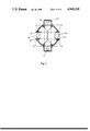
- FIG. 1 is a schematic representation in a sectional view perpendicular to the axis of rotation, of the structure of a microwave switch according to the invention
- FIG. 2 is a schematic representation, in a vertical sectional view, of the structure of a rotor of an internal waveguide switch according to a further embodiment
- FIG. 3 is a schematic representation, in a vertical sectional view, of the structure of the microwave switch standing, and including a rotor according to FIG. 2;
- FIG. 4 is a schematic representation, in a horizontal sectional view, of the structure of the microwave switch according to FIG. 3;
- FIG. 5 is a redundant circuit including two-way microwave switches according to the invention.
- FIG. 6 is a redundant circuit including four-way microwave switches according to the invention.
- the microwave switch according to FIG. 1 includes a rotor 2 rotatably mounted in a housing 1. Between the housing 1 and the rotor 2 there is disposed a small air gap.
- Two adapters 3 (for coupling to waveguide ports) are integrated in the housing 1, and a third adapter is connected on the right of it, and is screwed on.
- HF signals are coupled into the waveguide passages of each of the adapters 3 (only one of which is numbered in FIG. 1) in a generally known manner which will not be described in detail here.
- So-called tuning screws 6 and 7 are provided at each of the adapters 3 to set the transmission characteristics.
- Coaxial ports 4 each extend at a right angle to the waveguide sections 5 the adapters 3. This arrangement is appropriate in order to save space.
- the housing 1 is connected to a connecting member 12 at the location of a waveguide opening 11 in the housing 1.
- This connecting member 12 performs two functions: to permit measurement of the transmission characteristics of the microwave switch and to provide a connection the coaxial ports or conductors 4 via the waveguide passages 8 and 9 of the internal waveguide switch to a measuring instrument or device additionally, if the microwave switch is used in a redundant system, a further waveguide, likewise having reduced cross-sectional dimensions and leading to the next waveguide switch, may be coupled in at the connecting member 12.
- This has the advantage that adapters can be omitted and thus, due to the elimination of the adapters, the transmission characteristics of the entire circuit are improved.
- the walls may be composed of a plurality of sheet-like pieces.
- FIG. 2 is a vertical sectional view parallel to the rotor axis of the structure of a rotor 2 according to a further embodiment of an internal waveguide switch. Because of the waveguide passages 8, 9, having a relatively small thickness 13 in a direction which is parallel to the rotor axis, a very flat rotor 2 is created which is mounted so as to be rotatable through an angle of 360° about the rotor axis.
- the rotor 2 includes four waveguide passages 8, 9 for the connection of various waveguide sections (having a structure corresponding to that of the waveguide sections 5 of FIG. 1) of the waveguide switch in various switching positions. Two of these internal waveguide passages 8 serve the purpose of interconnecting oppositely disposed ones of the waveguide sections 5.
- the other two waveguide passages 9 connect adjacent ones of the waveguide sections passages 5 with one another.
- the waveguide passages 8 which connect oppositely disposed waveguide sections 5 with one another are angled in the vicinity of the edge of the rotor 2, avoiding sharp angles, and in the manner are each brought past the arcuate waveguide passages 9 in different planes.
- Chokes 14 disposed at the periphery of the rotor 2 serve to reduce crosstalk.
- FIG. 3 is a vertical sectional view parallel to the rotor axis of a microwave switch according to the further embodiment of FIG. 2, with the switch in a standing position and including a drive element 20.
- the drive element 20 for example a stepping motor, is mounted on the housing cover 19 of the microwave switch.
- One adapter (unnumber) is integrated in the top and one in the bottom of the housing 1 as seen in FIG. 1 respectively includes coaxial connectors 16, 17 which each have a coaxial inner conductor 18.
- the coaxial input line and the coaxial output line may be brought to the coaxial connectors 16, 17 of the microwave switch from opposite sides.
- the rotor 2 and its bearing (not shown) as well as the waveguide passages 8, 9 are disposed in the housing 1 of the microwave switch.
- FIG. 4 is a horizontal sectional view taken perpendicularly to the rotor axis of a microwave switch of the further embodiment.
- direct connections can be established, via two flanges 10, from one internal waveguide switch (not shown) to another internal waveguide switch, or alternatively waveguide switches of the further embodiment can be directly coupled together.
- the above-described features of the further embodiment frequently obviate the need for transitions between a coaxial line and a waveguide or a waveguide and a coaxial line in the redundant path, and the transmission characteristics of the redundant path are not significantly worsened.
- the walls of arcuate waveguide sections 9 are made of a plurality of sheet-like pieces.
- FIG. 5 shows the use of two-way microwave switches 21 to 24 according to the invention in a redundant system, with the signals arriving on four coaxial lines A-D and leaving through four (of a total of five) coaxial lines F-I which can be connected by way of four two-way switches 21-24 (S switches) which are configured internally as waveguide switches and which each have four ports labelled I-IV.
- Connections 25-27 from each of the microwave switches 22, 23, and 24, respectively, to microwave switches 21, 22, and 23, and these connections 25-27 are either configured to have special waveguides or the microwave switches are connected with one another directly at their flanges 10.
- Ports I and II of the two-way switches 21-24 and also the port IV of the microwave switch 21 are provided with adapters 3 for the connection of coaxial lines. Ports III and IV are provided with flanges 10 for the connection of special waveguides. Switch 24 is terminated at port III.
- the signals are fed to coaxial ports I of the switches via coaxial lines A-D.
- switches 21-24 are in such a position that the HF signals are carried through coaxial ports II and coaxial lines F-I to the subsequent amplifiers.
- the amplifier connected with coaxial line E at port IV of switch 21 is not in operation in the normal case.
- switch 23 is switched in such a way that the signal in coaxial line C at input I of switch 23 is conducted, via the flange 10 at port IV to the special waveguide 26, the flanges 10 at ports III and IV of switch 22, the special waveguide 25,the flange 10 at port III of switch 21, and the adapter 3 at port IV of the switch 21, and from there the signal is connected with an operational amplifier connected with the coaxial line E.
- the signal arriving in coaxial line C has only one coaxial line/waveguide transition and only one waveguide/coaxial line transition. With a purely coaxial switch, the signal would be attenuated considerably because of the required six coaxial line/coaxial line transitions.
- FIG. 6 shows the use of four-way microwave switches 28-31 according to the invention in a redundant system where the signals arriving on four coaxial lines A-D and leaving on four of the six coaxial lines can be switched by means of four four-way switches 28-31 arranged as (T-switches) which are internally configured as waveguide switches and which each have four ports.
- T-switches switches
- the connections from switch to switch are provided either to include special waveguides or the switches are directly connected with one another at their flanges 10.
- the four-way switches 28-31 are provided with adapters 3, while switches 28 and 31 are also provided with coaxial ports at ports IV and II, for the connection of coaxial lines.
- the ports II of the switches 28-30 and ports IV of switches 29-31 are provided with flanges 10 for the connection of special waveguides or for the direct connection of the internal waveguide switches with one another.
- the signals are fed to the coaxial ports I of switches 28-31 via coaxial lines A-D.
- switches 28-31 are in such positions that the HF signals travel via respective coaxial ports III and respective coaxial lines F-I to amplifiers connected to the lines F-I.
- the amplifiers connected with coaxial lines E and K of switches 28 and 31 are not in operation in the normal case.
- the two switches 28 and 29 are switched in such a manner that the signal on coaxial line A at input I of switch 28 is fed, via adapter 3 at port IV and coaxial line E, to the next following amplifier.
- the signal on coaxial line B at port I of switch 29 is conducted via the flange 10 at port II, the special waveguide 33, the flange 10 at port IV of switch 30, the flange 10 at port II, the special waveguide 34, the flange 10 at port IV of switch 31, and the adapter at port II to the coaxial line K, which conducts the signal to the subsequent amplifier.
- the signals in lines A and B have only one coaxial line/waveguide and waveguide/coaxial line transition and are thus not attenuated as much as in a circuit having purely coaxial switches.
- the special configuration of the waveguide passages in the switches and the special waveguide between the switches has the significance that the dimensions of the switches are selected to be smaller than to the standard waveguide dimensions customary for the frequencies to be transmitted. Preferably, the small dimensions are made very much smaller. For example, for 10 to 15 GHz, instead of a height dimension of 9.5 mm and a width of 19 mm, waveguides are selected which have a 4.75 mm height dimension and are 19 mm wide.
Landscapes
- Waveguide Switches, Polarizers, And Phase Shifters (AREA)
Applications Claiming Priority (2)
| Application Number | Priority Date | Filing Date | Title |
|---|---|---|---|
| DE3605043 | 1986-02-18 | ||
| DE3605043 | 1986-02-18 |
Publications (1)
| Publication Number | Publication Date |
|---|---|
| US4945320A true US4945320A (en) | 1990-07-31 |
Family
ID=6294318
Family Applications (1)
| Application Number | Title | Priority Date | Filing Date |
|---|---|---|---|
| US07/264,954 Expired - Fee Related US4945320A (en) | 1986-02-18 | 1987-02-17 | Microwave switch having at least two switching positions |
Country Status (4)
| Country | Link |
|---|---|
| US (1) | US4945320A (fr) |
| EP (1) | EP0293386B1 (fr) |
| DE (1) | DE3779117D1 (fr) |
| WO (1) | WO1987005155A1 (fr) |
Cited By (9)
| Publication number | Priority date | Publication date | Assignee | Title |
|---|---|---|---|---|
| US5155456A (en) * | 1988-06-28 | 1992-10-13 | Teldix Gmbh | Microwave switch arrangement |
| US5347243A (en) * | 1992-12-23 | 1994-09-13 | Hughes Aircraft Company | Non-contacting waveguide "T" switch |
| US6816026B2 (en) * | 1998-12-22 | 2004-11-09 | The Aerospace Corporation | Orthogonal polarization and frequency selectable waveguide using rotatable waveguide sections |
| US9368851B2 (en) | 2012-12-27 | 2016-06-14 | Space Systems/Loral, Llc | Waveguide T-switch |
| WO2021237249A1 (fr) * | 2020-05-21 | 2021-11-25 | John Lafergola | Commutateur de guides d'ondes |
| US11205825B2 (en) * | 2018-03-23 | 2021-12-21 | Victor Nelson | Non-contact type coaxial switch |
| CN114976531A (zh) * | 2022-05-25 | 2022-08-30 | 中国航天时代电子有限公司 | 一种新型顺序切换波导开关 |
| US11579696B2 (en) | 2017-03-23 | 2023-02-14 | Mindmaze Group Sa | System, method and apparatus for accurately measuring haptic forces |
| US20230359230A1 (en) * | 2022-05-03 | 2023-11-09 | Electra Aero, Inc. | Systems and Methods For Controlling Fluid Flow |
Families Citing this family (3)
| Publication number | Priority date | Publication date | Assignee | Title |
|---|---|---|---|---|
| US4908589A (en) * | 1987-09-21 | 1990-03-13 | Hughes Aircraft Company | Dielectrically loaded waveguide switch |
| CH675927A5 (fr) * | 1988-01-26 | 1990-11-15 | Asea Brown Boveri | |
| FR2638572B1 (fr) * | 1988-10-28 | 1990-12-07 | Thomson Csf | Dispositif de couplage de deux sources de signaux hyperfrequence avec reduction de la perte en cas de panne d'une source |
Citations (3)
| Publication number | Priority date | Publication date | Assignee | Title |
|---|---|---|---|---|
| US4201963A (en) * | 1978-01-26 | 1980-05-06 | Communications Satellite Corporation | 3-Position, 4-port waveguide switch |
| US4463324A (en) * | 1982-06-03 | 1984-07-31 | Sperry Corporation | Miniature coaxial line to waveguide transition |
| US4761622A (en) * | 1985-10-31 | 1988-08-02 | The General Electric Company, P.L.C. | Waveguide switching apparatus |
Family Cites Families (6)
| Publication number | Priority date | Publication date | Assignee | Title |
|---|---|---|---|---|
| FR947965A (fr) * | 1947-05-22 | 1949-07-19 | Csf | Distributeur tournant d'ondes ultra-courtes |
| GB730219A (en) * | 1951-11-29 | 1955-05-18 | Airtron Inc | Waveguide switches |
| BE522303A (fr) * | 1952-04-08 | 1900-01-01 | ||
| DE1028639B (de) * | 1956-10-11 | 1958-04-24 | Siemens Ag | Einseitig kurzgeschlossener Hohlleiter-abschnitt, der mit einer Vorrichtung zum Anschluss einer Koaxialleitung versehen ist |
| US3141943A (en) * | 1961-07-17 | 1964-07-21 | Don Lan Electronics Inc | Co-axial switch |
| GB1020335A (en) * | 1963-09-04 | 1966-02-16 | Ass Elect Ind | Improvements relating to switches for microwave circuits using waveguides |
-
1987
- 1987-02-17 WO PCT/EP1987/000089 patent/WO1987005155A1/fr not_active Ceased
- 1987-02-17 EP EP87901448A patent/EP0293386B1/fr not_active Expired - Lifetime
- 1987-02-17 DE DE8787901448T patent/DE3779117D1/de not_active Expired - Lifetime
- 1987-02-17 US US07/264,954 patent/US4945320A/en not_active Expired - Fee Related
Patent Citations (3)
| Publication number | Priority date | Publication date | Assignee | Title |
|---|---|---|---|---|
| US4201963A (en) * | 1978-01-26 | 1980-05-06 | Communications Satellite Corporation | 3-Position, 4-port waveguide switch |
| US4463324A (en) * | 1982-06-03 | 1984-07-31 | Sperry Corporation | Miniature coaxial line to waveguide transition |
| US4761622A (en) * | 1985-10-31 | 1988-08-02 | The General Electric Company, P.L.C. | Waveguide switching apparatus |
Cited By (11)
| Publication number | Priority date | Publication date | Assignee | Title |
|---|---|---|---|---|
| US5155456A (en) * | 1988-06-28 | 1992-10-13 | Teldix Gmbh | Microwave switch arrangement |
| US5347243A (en) * | 1992-12-23 | 1994-09-13 | Hughes Aircraft Company | Non-contacting waveguide "T" switch |
| US6816026B2 (en) * | 1998-12-22 | 2004-11-09 | The Aerospace Corporation | Orthogonal polarization and frequency selectable waveguide using rotatable waveguide sections |
| US9368851B2 (en) | 2012-12-27 | 2016-06-14 | Space Systems/Loral, Llc | Waveguide T-switch |
| US11579696B2 (en) | 2017-03-23 | 2023-02-14 | Mindmaze Group Sa | System, method and apparatus for accurately measuring haptic forces |
| US11205825B2 (en) * | 2018-03-23 | 2021-12-21 | Victor Nelson | Non-contact type coaxial switch |
| WO2021237249A1 (fr) * | 2020-05-21 | 2021-11-25 | John Lafergola | Commutateur de guides d'ondes |
| US20230359230A1 (en) * | 2022-05-03 | 2023-11-09 | Electra Aero, Inc. | Systems and Methods For Controlling Fluid Flow |
| US12271213B2 (en) * | 2022-05-03 | 2025-04-08 | Electra Aero, Inc. | Systems and methods for controlling fluid flow |
| CN114976531A (zh) * | 2022-05-25 | 2022-08-30 | 中国航天时代电子有限公司 | 一种新型顺序切换波导开关 |
| CN114976531B (zh) * | 2022-05-25 | 2023-09-26 | 中国航天时代电子有限公司 | 一种新型顺序切换波导开关 |
Also Published As
| Publication number | Publication date |
|---|---|
| DE3779117D1 (de) | 1992-06-17 |
| EP0293386A1 (fr) | 1988-12-07 |
| WO1987005155A1 (fr) | 1987-08-27 |
| EP0293386B1 (fr) | 1992-05-13 |
Similar Documents
| Publication | Publication Date | Title |
|---|---|---|
| US4945320A (en) | Microwave switch having at least two switching positions | |
| US4242652A (en) | Four port waveguide switch | |
| EP0116418A2 (fr) | Jonction micro-ondes multi-portes et multi-fréquences | |
| US4201963A (en) | 3-Position, 4-port waveguide switch | |
| US2432476A (en) | Electrical switch device | |
| US3999151A (en) | Crossguide hybrid coupler and a commutating hybrid using same to form a channel branching network | |
| EP0567267A2 (fr) | Diviseurs/combineurs à micro-ondes isolant les signaux | |
| US4061989A (en) | Redundancy switching system | |
| US6169518B1 (en) | Dual beam monopulse antenna system | |
| US4761622A (en) | Waveguide switching apparatus | |
| US4502026A (en) | Signal distributing apparatus | |
| CN101379656A (zh) | 天线馈送装置 | |
| CA1278115C (fr) | Multiplexeur de guide d'ondes couple par une sonde | |
| US4119931A (en) | Transmission line switch | |
| US4093928A (en) | Microstrip hybrid ring coupler | |
| US10522888B2 (en) | Microwave branching switch | |
| US4231000A (en) | Antenna feed system for double polarization | |
| US4151489A (en) | Waveguide switch having four ports and three connecting states | |
| US5347243A (en) | Non-contacting waveguide "T" switch | |
| US6201906B1 (en) | Compact waveguide “T” switch | |
| SE505914C2 (sv) | Kopplingsanordning | |
| US3885117A (en) | Balanced line switch system | |
| CN222168654U (zh) | 旋转组合结构 | |
| JPH0531841B2 (fr) | ||
| JP3175325B2 (ja) | 可変移相4分配器 |
Legal Events
| Date | Code | Title | Description |
|---|---|---|---|
| AS | Assignment |
Owner name: TELDIX GMBH, GERMANY Free format text: ASSIGNMENT OF ASSIGNORS INTEREST.;ASSIGNORS:HETTLAGE, ECKART;RUFF, GERD;REEL/FRAME:005004/0602 Effective date: 19880630 |
|
| FEPP | Fee payment procedure |
Free format text: PAYOR NUMBER ASSIGNED (ORIGINAL EVENT CODE: ASPN); ENTITY STATUS OF PATENT OWNER: LARGE ENTITY |
|
| FPAY | Fee payment |
Year of fee payment: 4 |
|
| AS | Assignment |
Owner name: ROBERT BOSCH GMBH, GERMANY Free format text: ASSIGNMENT OF ASSIGNORS INTEREST;ASSIGNOR:TELDIX GMBH;REEL/FRAME:008401/0750 Effective date: 19961203 |
|
| FPAY | Fee payment |
Year of fee payment: 8 |
|
| REMI | Maintenance fee reminder mailed | ||
| LAPS | Lapse for failure to pay maintenance fees | ||
| STCH | Information on status: patent discontinuation |
Free format text: PATENT EXPIRED DUE TO NONPAYMENT OF MAINTENANCE FEES UNDER 37 CFR 1.362 |
|
| FP | Lapsed due to failure to pay maintenance fee |
Effective date: 20020731 |