US4954671A - Connectible switching device - Google Patents
Connectible switching device Download PDFInfo
- Publication number
- US4954671A US4954671A US07/323,347 US32334789A US4954671A US 4954671 A US4954671 A US 4954671A US 32334789 A US32334789 A US 32334789A US 4954671 A US4954671 A US 4954671A
- Authority
- US
- United States
- Prior art keywords
- coupling element
- jaw
- shaped coupling
- switching
- cone
- Prior art date
- Legal status (The legal status is an assumption and is not a legal conclusion. Google has not performed a legal analysis and makes no representation as to the accuracy of the status listed.)
- Expired - Lifetime
Links
- 230000008878 coupling Effects 0.000 claims abstract description 60
- 238000010168 coupling process Methods 0.000 claims abstract description 60
- 238000005859 coupling reaction Methods 0.000 claims abstract description 60
- 230000035515 penetration Effects 0.000 claims description 6
- 230000033001 locomotion Effects 0.000 claims description 3
- 230000005404 monopole Effects 0.000 description 2
- 230000005405 multipole Effects 0.000 description 2
- 238000010276 construction Methods 0.000 description 1
- 230000004048 modification Effects 0.000 description 1
- 238000012986 modification Methods 0.000 description 1
Images

Classifications
-
- H—ELECTRICITY
- H01—ELECTRIC ELEMENTS
- H01H—ELECTRIC SWITCHES; RELAYS; SELECTORS; EMERGENCY PROTECTIVE DEVICES
- H01H71/00—Details of the protective switches or relays covered by groups H01H73/00 - H01H83/00
- H01H71/10—Operating or release mechanisms
- H01H71/12—Automatic release mechanisms with or without manual release
- H01H71/46—Automatic release mechanisms with or without manual release having means for operating auxiliary contacts additional to the main contacts
- H01H71/462—Automatic release mechanisms with or without manual release having means for operating auxiliary contacts additional to the main contacts housed in a separate casing, juxtaposed to and having the same general contour as the main casing
-
- H—ELECTRICITY
- H01—ELECTRIC ELEMENTS
- H01H—ELECTRIC SWITCHES; RELAYS; SELECTORS; EMERGENCY PROTECTIVE DEVICES
- H01H71/00—Details of the protective switches or relays covered by groups H01H73/00 - H01H83/00
- H01H71/10—Operating or release mechanisms
- H01H71/1009—Interconnected mechanisms
- H01H71/1018—Interconnected mechanisms with only external interconnections
-
- Y—GENERAL TAGGING OF NEW TECHNOLOGICAL DEVELOPMENTS; GENERAL TAGGING OF CROSS-SECTIONAL TECHNOLOGIES SPANNING OVER SEVERAL SECTIONS OF THE IPC; TECHNICAL SUBJECTS COVERED BY FORMER USPC CROSS-REFERENCE ART COLLECTIONS [XRACs] AND DIGESTS
- Y10—TECHNICAL SUBJECTS COVERED BY FORMER USPC
- Y10S—TECHNICAL SUBJECTS COVERED BY FORMER USPC CROSS-REFERENCE ART COLLECTIONS [XRACs] AND DIGESTS
- Y10S200/00—Electricity: circuit makers and breakers
- Y10S200/06—Tie bar
Definitions
- the present invention relates to a switching device in a system of switching devices, which can be coupled to mountable switching, auxiliary switching, or signal switching devices.
- a multipole switch is constructed from a monopole circuit-breaker, whereby the actuating handles are interconnected with a busbar-type bridge.
- the handles have central recesses on their front sides, into which knobs engage with clearance in the longitudinal direction of the bridge.
- a switching device in a system of switching devices which can be coupled to mountable switching, auxiliary switching or signal devices, comprising a housing, a cylindrical, manually operated part disposed in the housing having a selector, a coupling element consisting of a pair, according to function, of a jaw-shaped and a cone-shaped coupling element constructed on the cylindrical part in the direction of the switching axis on a mounting side, with which the other coupling element of the function pair can be forced into engagement connection, wherein the jaw-like coupling element has a jaw tooth in engagement depth only for one coupling direction for a shallower penetration of a cone-like coupling element.
- a jaw-shaped coupling element can be arranged on the cylindrical part in the direction of the switching axis on a mounting side of the housing, for example, and works together with the cone-shaped coupling element in a housing slot on a surface of the housing, which engages from a device to be attached into the jaw-shaped coupling element on the mounting side of a target device.
- the jaw-shaped coupling element is designed only for one coupling direction with a jaw tooth or a jaw flank of the jaw-shaped coupling element in engagement depth.
- the cone-shaped coupling element of the switching device to be attached is designed just short enough, so that the jaw-shaped coupling element of a circuit-breaker, in the case of a provided second, shorter penetration depth, forms a jaw tooth only in the switch-on direction, then the switching device to be attached remains intact, when switching off manually. Thereby, one can easily fulfill the conditions that are required between signal circuit controllers and circuit-breakers of the error-signal circuit controller type.
- Such a signal circuit controller can only be switched on by the selector of the circuit-breaker, but can no longer be switched off by it.
- the signal circuit controller can only emit a signal, if the circuit-breaker has responded in automatic tripping action.
- a separate tripping coupling assures, in normal operation, that the signal circuit controller is switched off, only when there is an overload condition, whether it be an overcurrent or a short circuit of the circuit protected by the circuit-breaker.
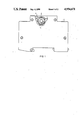
- FIG. 1 shows a connectible switching device, designed as a circuit-breaker, reproduced in its longitudinal direction, and with a part thereof shown in a cut-away view;
- FIG. 2 shows a manually operated part of the switching device of FIG. 1 reproduced in larger scale
- FIG. 3 shows a sectional view along line 3--3 of FIG. 2, together with a cone-shaped coupling element of an auxiliary switch to be attached;
- FIG. 4 shows a view of the representation of FIG. 3 rotated by 90°.
- the switching device 1 of FIG. 1 has a cylindrical, manually operated part 2 with a selector 3, which protrudes from a housing 5.1.
- a jaw-shaped coupling element 4 is arranged on the cylindrical part 2 in the direction of the switching axis on a mounting side, behind the drawing plane.
- the coupling element 4 is movable with its mounting behind a housing slot 5.
- a cone-shaped coupling element 6 of FIG. 3 is arranged in the housing slot on a surface. In one embodiment, the cone-shaped coupling element 6 engages deeply with the jaw-shaped coupling element 4.
- the cone-shaped coupling element 6 may be designed in two versions, a long version 6.1 and a short version 6.2.
- the cone-shaped coupling element engages between the jaw teeth 7 and 8.
- the teeth engaged are 7 and 8.1.
Landscapes
- Driving Mechanisms And Operating Circuits Of Arc-Extinguishing High-Tension Switches (AREA)
- Excavating Of Shafts Or Tunnels (AREA)
- Investigating Or Analyzing Materials By The Use Of Ultrasonic Waves (AREA)
- Transmitters (AREA)
- Structure Of Receivers (AREA)
- Details Of Connecting Devices For Male And Female Coupling (AREA)
- Magnetic Resonance Imaging Apparatus (AREA)
- Switches With Compound Operations (AREA)
- Massaging Devices (AREA)
- Friction Gearing (AREA)
- Breakers (AREA)
Applications Claiming Priority (2)
| Application Number | Priority Date | Filing Date | Title |
|---|---|---|---|
| DE3808472 | 1988-03-14 | ||
| DE3808472 | 1988-03-14 |
Publications (1)
| Publication Number | Publication Date |
|---|---|
| US4954671A true US4954671A (en) | 1990-09-04 |
Family
ID=6349695
Family Applications (1)
| Application Number | Title | Priority Date | Filing Date |
|---|---|---|---|
| US07/323,347 Expired - Lifetime US4954671A (en) | 1988-03-14 | 1989-03-14 | Connectible switching device |
Country Status (8)
| Country | Link |
|---|---|
| US (1) | US4954671A (de) |
| EP (1) | EP0332936B1 (de) |
| AT (1) | ATE106603T1 (de) |
| AU (1) | AU616738B2 (de) |
| BR (1) | BR8901158A (de) |
| DE (2) | DE8816387U1 (de) |
| ES (1) | ES2053832T3 (de) |
| ZA (1) | ZA891876B (de) |
Citations (5)
| Publication number | Priority date | Publication date | Assignee | Title |
|---|---|---|---|---|
| US2824191A (en) * | 1953-02-05 | 1958-02-18 | Fed Electric Prod Co | Circuit breakers |
| DE1044937B (de) * | 1956-11-27 | 1958-11-27 | Elektro App Werke J W Stalin V | Kupplungsanordnung fuer zwei nebeneinander angeordnete, ueber einen gemeinsamen Schalthebel betaetigte, mit Kniehebelverriegelung versehene einpolige Selbstschalter oderSchaltwerke fuer Selbstschalter, insbesondere Kleinselbstschalter, zur Erreichung eines zweipoligen Schaltsystems |
| DE1286620B (de) * | 1962-03-26 | 1969-01-09 | Licentia Gmbh | Schaltmechanismus fuer Selbstschalter |
| US3464045A (en) * | 1967-05-11 | 1969-08-26 | Gen Electric | Circuit breaker selective trip mechanism |
| US4385214A (en) * | 1981-08-14 | 1983-05-24 | Square D Company | Interlock pushbutton assembly |
Family Cites Families (1)
| Publication number | Priority date | Publication date | Assignee | Title |
|---|---|---|---|---|
| FR2615322B1 (fr) * | 1987-05-11 | 1989-06-30 | Merlin Gerin | Barre de declenchement d'un bloc disjoncteur multipolaire associe a un bloc declencheur auxiliaire |
-
1988
- 1988-03-14 DE DE8816387U patent/DE8816387U1/de not_active Expired
-
1989
- 1989-03-01 DE DE58907726T patent/DE58907726D1/de not_active Expired - Fee Related
- 1989-03-01 EP EP89103582A patent/EP0332936B1/de not_active Expired - Lifetime
- 1989-03-01 AT AT89103582T patent/ATE106603T1/de not_active IP Right Cessation
- 1989-03-01 ES ES89103582T patent/ES2053832T3/es not_active Expired - Lifetime
- 1989-03-10 AU AU31203/89A patent/AU616738B2/en not_active Ceased
- 1989-03-13 ZA ZA891876A patent/ZA891876B/xx unknown
- 1989-03-13 BR BR898901158A patent/BR8901158A/pt not_active IP Right Cessation
- 1989-03-14 US US07/323,347 patent/US4954671A/en not_active Expired - Lifetime
Patent Citations (5)
| Publication number | Priority date | Publication date | Assignee | Title |
|---|---|---|---|---|
| US2824191A (en) * | 1953-02-05 | 1958-02-18 | Fed Electric Prod Co | Circuit breakers |
| DE1044937B (de) * | 1956-11-27 | 1958-11-27 | Elektro App Werke J W Stalin V | Kupplungsanordnung fuer zwei nebeneinander angeordnete, ueber einen gemeinsamen Schalthebel betaetigte, mit Kniehebelverriegelung versehene einpolige Selbstschalter oderSchaltwerke fuer Selbstschalter, insbesondere Kleinselbstschalter, zur Erreichung eines zweipoligen Schaltsystems |
| DE1286620B (de) * | 1962-03-26 | 1969-01-09 | Licentia Gmbh | Schaltmechanismus fuer Selbstschalter |
| US3464045A (en) * | 1967-05-11 | 1969-08-26 | Gen Electric | Circuit breaker selective trip mechanism |
| US4385214A (en) * | 1981-08-14 | 1983-05-24 | Square D Company | Interlock pushbutton assembly |
Also Published As
| Publication number | Publication date |
|---|---|
| DE58907726D1 (de) | 1994-07-07 |
| AU616738B2 (en) | 1991-11-07 |
| ES2053832T3 (es) | 1994-08-01 |
| BR8901158A (pt) | 1989-10-31 |
| DE8816387U1 (de) | 1989-06-08 |
| EP0332936A1 (de) | 1989-09-20 |
| ATE106603T1 (de) | 1994-06-15 |
| EP0332936B1 (de) | 1994-06-01 |
| AU3120389A (en) | 1989-09-14 |
| ZA891876B (en) | 1989-10-25 |
Similar Documents
| Publication | Publication Date | Title |
|---|---|---|
| CA1084973A (en) | Rotor assembly and electrical switch including such assembly | |
| DE3875376D1 (de) | Ausloesekupplungshebel fuer einen mehrpoligen, mit einem ausloeseblock zusammenwirkenden leistungsschutzschalterblock. | |
| EP1039499A3 (de) | Betätigungshebeleinheit für elektrische Lastschalter | |
| AU3726689A (en) | A rubber stop assembly for a multipole circuit breaker | |
| EP0018133B1 (de) | Elektrischer Schalter mit mehreren Wählern | |
| EP0367102A3 (de) | Kurzschlussmelder | |
| MXPA01011395A (es) | Interruptor de palanca de control de multiples funciones. | |
| EP0362845A3 (de) | Ferngesteuerter Leistungsschalter | |
| CA2011960A1 (en) | Interlocking device for push-button switch | |
| EP0362846A3 (de) | Ferngesteuerter Leistungsschalter | |
| HK97487A (en) | Multiple switch using a rotary actuator | |
| US6160227A (en) | Toggle switch stop | |
| CA2235878A1 (en) | Switch connector | |
| US4954671A (en) | Connectible switching device | |
| GB1447780A (en) | Elecgrical circuit breakers | |
| EP1557851A1 (de) | Handgriffbefestigung für einen elektrischen Schalter | |
| US4379973A (en) | Universal logic switch | |
| EP0364950A3 (de) | Ferngesteuerter Schutzschalter | |
| KR100461682B1 (ko) | 슬라이더 작동 스위치 | |
| CA2286228A1 (en) | Electrical switch | |
| EP0745914B1 (de) | Multifunktionellen Zeitgeber | |
| DE58908823D1 (de) | Elektrisches Schaltgerät. | |
| CA2207562A1 (en) | Multi-functional electrical switch assembly with momentary operating mechanism | |
| EP0777244A3 (de) | Ein Schalter mit Ein- und Ausverriegelung | |
| WO2005060459A3 (en) | Efficient multiple-band antenna switching circuit |
Legal Events
| Date | Code | Title | Description |
|---|---|---|---|
| AS | Assignment |
Owner name: SIEMENS AKTIENGESELLSCHAFT, ORGANIZED UNDER THE FE Free format text: ASSIGNMENT OF ASSIGNORS INTEREST.;ASSIGNOR:SCHMIDT, HANS;REEL/FRAME:005074/0188 Effective date: 19890427 |
|
| STCF | Information on status: patent grant |
Free format text: PATENTED CASE |
|
| FEPP | Fee payment procedure |
Free format text: PAYOR NUMBER ASSIGNED (ORIGINAL EVENT CODE: ASPN); ENTITY STATUS OF PATENT OWNER: LARGE ENTITY |
|
| FPAY | Fee payment |
Year of fee payment: 4 |
|
| FPAY | Fee payment |
Year of fee payment: 8 |
|
| FPAY | Fee payment |
Year of fee payment: 12 |