US4982398A - Optical recording apparatus for forming grooves and pits in an optically recordable disc - Google Patents
Optical recording apparatus for forming grooves and pits in an optically recordable disc Download PDFInfo
- Publication number
- US4982398A US4982398A US07/225,917 US22591788A US4982398A US 4982398 A US4982398 A US 4982398A US 22591788 A US22591788 A US 22591788A US 4982398 A US4982398 A US 4982398A
- Authority
- US
- United States
- Prior art keywords
- disc
- recording beam
- recording
- groove
- radial direction
- Prior art date
- Legal status (The legal status is an assumption and is not a legal conclusion. Google has not performed a legal analysis and makes no representation as to the accuracy of the status listed.)
- Ceased
Links
Images

Classifications
-
- G—PHYSICS
- G11—INFORMATION STORAGE
- G11B—INFORMATION STORAGE BASED ON RELATIVE MOVEMENT BETWEEN RECORD CARRIER AND TRANSDUCER
- G11B7/00—Recording or reproducing by optical means, e.g. recording using a thermal beam of optical radiation by modifying optical properties or the physical structure, reproducing using an optical beam at lower power by sensing optical properties; Record carriers therefor
- G11B7/24—Record carriers characterised by shape, structure or physical properties, or by the selection of the material
- G11B7/26—Apparatus or processes specially adapted for the manufacture of record carriers
- G11B7/261—Preparing a master, e.g. exposing photoresist, electroforming
-
- G—PHYSICS
- G11—INFORMATION STORAGE
- G11B—INFORMATION STORAGE BASED ON RELATIVE MOVEMENT BETWEEN RECORD CARRIER AND TRANSDUCER
- G11B7/00—Recording or reproducing by optical means, e.g. recording using a thermal beam of optical radiation by modifying optical properties or the physical structure, reproducing using an optical beam at lower power by sensing optical properties; Record carriers therefor
- G11B7/004—Recording, reproducing or erasing methods; Read, write or erase circuits therefor
- G11B7/0045—Recording
-
- G—PHYSICS
- G11—INFORMATION STORAGE
- G11B—INFORMATION STORAGE BASED ON RELATIVE MOVEMENT BETWEEN RECORD CARRIER AND TRANSDUCER
- G11B7/00—Recording or reproducing by optical means, e.g. recording using a thermal beam of optical radiation by modifying optical properties or the physical structure, reproducing using an optical beam at lower power by sensing optical properties; Record carriers therefor
- G11B7/12—Heads, e.g. forming of the optical beam spot or modulation of the optical beam
- G11B7/125—Optical beam sources therefor, e.g. laser control circuitry specially adapted for optical storage devices; Modulators, e.g. means for controlling the size or intensity of optical spots or optical traces
- G11B7/128—Modulators
-
- G—PHYSICS
- G11—INFORMATION STORAGE
- G11B—INFORMATION STORAGE BASED ON RELATIVE MOVEMENT BETWEEN RECORD CARRIER AND TRANSDUCER
- G11B7/00—Recording or reproducing by optical means, e.g. recording using a thermal beam of optical radiation by modifying optical properties or the physical structure, reproducing using an optical beam at lower power by sensing optical properties; Record carriers therefor
- G11B7/24—Record carriers characterised by shape, structure or physical properties, or by the selection of the material
- G11B7/2407—Tracks or pits; Shape, structure or physical properties thereof
- G11B7/24073—Tracks
- G11B7/24079—Width or depth
Definitions
- the present invention relates to an optical recording apparatus to form a preformat onto an optical disc.
- FIG. 1 shows the region in which pits 31 are preformed and a wide groove 32 mixedly exist on a recordable optical disc. Hitherto, in the case of forming patterns of different widths onto a mother disc, the pits 31, groove 32, and recording spots corresponding to their widths are prepared and both of these recording spots are switched.
- TOC Table of Contents
- the ratio of the sizes of the spots cannot be set to a large value. For example, both having a spot of the width of 0.5 [ ⁇ m] and the groove of the width of 1.1 [ ⁇ m] cannot be formed.
- the laser power since it is necessary to form two beams, the laser power must to be set to a large value.
- the groove width is easily changed due the exposure level and developing condition.
- an optical recording apparatus so as to form a tracking groove onto an optically recordable disc, comprising: recording beam generating means for generating a recording beam having a predetermined spot size so as to form a pattern of a predetermined width onto the disc; light deflecting means arranged on an optical path of the recording beam generating means; and drive means for driving the light deflecting means, for reciprocatingly moving the recording beam in a radial direction of the disc at a high frequency, and for multiply exposing the disc with the recording beam due to the movement of the recording beam in the radial direction, so that a groove having a width wider than the pattern of the predetermined width is formed.
- the recording beam having a spot size so as to record a discrete information pattern, i.e., pits is generated.
- the pits are formed by this recording beam.
- the central locus of the pits is wobbled.
- the recording beam is swung in the radial direction of the disc, a wide groove is formed.
- the recording beam is swung by the signal having a high frequency, a multiexposure is performed.
- the central locus of the wide groove formed in this manner is wobbled. Both of the pits and the wide groove are formed by using the single recording beam as explained above.
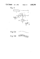
- FIG. l a schematic diagram showing a signal pattern on a disc to which the present invention can be applied;
- FIG. 2 is a block diagram of an embodiment of the present invention
- FIGS. 3A and 3B are schematic diagrams for use in the explanation of the operation of the embodiment of the invention.
- FIG. 4 is a block diagram of another embodiment of the invention.
- FIGS. 5A and 5B are schematic diagrams for use in explanation of the operation of another embodiment of the invention.
- reference numeral 1 denotes an optically recordable disc (mother disc).
- a photo resist is coated on the disc 1 so as to have a uniform thickness.
- Reference numeral 2 denotes a laser, for instance, an argon ion laser. A recording beam from the laser 2 is led to a light modulator 3 using the acoustic optical effect.
- a signal from an input terminal 4 is supplied to the light modulator 3 through a driver 5.
- the signal input in the terminal 4 is the EFM (8-14 modulation) signal (pulse signal).
- the recording beam is turned on/off by the EFM signal.
- the signal input in the terminal 4 is a DC signal of a predetermined level. The recording beam is turned on by the DC signal.
- the recording beam output from the light modulator 3 is supplied to a light deflector 6 using the acoustic optical effect.
- the foregoing light modulator 3 changes the intensity of the diffracted light with the frequency of the ultrasonic wave held constant.
- the light deflector 6 changes the frequency of the ultrasonic wave with the intensity of the diffracted light held constant, thereby causing the deflection.
- the recording beam output from the light deflector 6 is irradiated onto the disc 1 through an intermediate lens 7 and an objective lens 8.
- the disc 1 is rotated by a spindle motor 9 at the constant linear velocity (CLV).
- a high frequency signal formed by a voltage controlled oscillator (VCO) 11 is supplied to the light deflector 6 through a driver 12.
- the frequency of the high frequency signal is changed so as to wobble the recording beam with the light deflector 6.
- a control signal is supplied from a terminal 10 to the VCO 11.
- the frequency of the high frequency signal which is generated from the VCO changes by the frequency f w , so that the recording beam is swung by the frequency f w .
- a sync signal, an address signal, and the like are recorded by frequency modulating or phase modulating the control signal S a .
- a signal S b having a sufficiently high frequency f 0 is supplied as a control signal together with, the signal S a to the VCO 11. Assuming that a spot size of a predetermined width to be recorded by the recording beam is d and that the linear velocity during recording is v, the frequency f 0 is selected to be
- the frequency f 0 is set to (f 0 >2.5 MHz, e.g. 5 MHZ).
- the groove portion the recording spot produces a locus in the width direction and multi-exposes the portion in the area, so that a wide groove portion 32' is obtained. Therefore, after the photo resist is developed, the pits corresponding to the pit portion 31' and the wide groove corresponding to the wide groove portion 32' wobbled by the frequency f w is obtained.
- the width w of the groove can be changed within a range of (d ⁇ w ⁇ q) (q: track pitch) by the amplitude of the signal S b .
- the signal of the frequency f w is not limited to a sine wave signal but may be a clock signal or a signal which is frequency modulated by the absolute time information of the CD.
- FIG. 4 shows another embodiment of the present invention.
- the modulation and deflection are performed by a single device (called a light modulation deflector) which is different from the foregoing embodiment in which the different light modulator 3 and light deflector 6 are independently used.
- the recording beam from the laser 2 is input to a light modulation deflector 22 through an intermediate lens 21.
- the light modulation deflector 22 uses the acoustic optical effect.
- the intermediate lens 21 is provided to focus the spot size.
- the position of the focal distance F of the intermediate lens 21 and the center of the light modulation deflector 22 are spaced away from each other by only a distance of d f . Even if the light modulation deflector 22 performs the deflection on the focal point of the intermediate lens 21, the wobbling is not executed on the disc 1. As the distance d f is set to a large value, the amount of wobbling on the disc increases.
- df is determined in accordance with the necessary amount of wobbling amount.
- ⁇ d denotes a deflecting angle.
- a high frequency signal from a driver 23 is supplied to the light modulation deflector 22.
- An EFM signal (pulse signal) is supplied from a terminal 24 to the driver 23.
- An output signal of the driver 23 is turned on/off in accordance with the logic levels of "0" and “1" of the EFM signal.
- the signal of the "1" level of the EFM signal from the terminal 24 is supplied.
- the EFM signal is set to the "0" level, the output signal of the driver 23 is turned off and the recording beam is not irradiated onto the disc 1.
- the pit corresponding to the EFM signal supplied from the terminal 24 is formed on the disc 1.
- the high frequency signal from a VCO 25 is supplied to the driver 23.
- a control signal from a terminal 26 is supplied to the VCO 25.
- this control signal is the signal having the frequency of 22.05 kHz as shown in FIG. 5A.
- this control signal is the multiplexed signal of the signal of 22.05 kHz and the signal of 5 MHz as shown in FIG. 5B.
- the VCO 25 has a center frequency of, e.g., 224 MHz. A frequency of an output signal of the VCO 25 changes in accordance with a signal from the terminal 26.
- the output signal of the VCO 25 is supplied to the light modulation deflector 22 through the driver 23, so that the wobbling is performed and the wide groove is formed.
- both of them can be formed by using a single recording beam. Therefore, different from the apparatus which independently uses different recording beams, the following advantages are obtained.
- the width is electrically controlled and a groove of a desired width can be easily formed.
Landscapes
- Physics & Mathematics (AREA)
- Optics & Photonics (AREA)
- Engineering & Computer Science (AREA)
- Manufacturing & Machinery (AREA)
- Optical Recording Or Reproduction (AREA)
- Optical Head (AREA)
- Manufacturing Optical Record Carriers (AREA)
Priority Applications (1)
| Application Number | Priority Date | Filing Date | Title |
|---|---|---|---|
| US07/926,511 USRE34719E (en) | 1987-07-31 | 1992-08-03 | Optical recording apparatus for forming grooves and pits in an optically recordable disc |
Applications Claiming Priority (2)
| Application Number | Priority Date | Filing Date | Title |
|---|---|---|---|
| JP62192229A JP2643159B2 (ja) | 1987-07-31 | 1987-07-31 | 光学的記録方法 |
| JP62-192229 | 1987-07-31 |
Related Child Applications (1)
| Application Number | Title | Priority Date | Filing Date |
|---|---|---|---|
| US07/926,511 Reissue USRE34719E (en) | 1987-07-31 | 1992-08-03 | Optical recording apparatus for forming grooves and pits in an optically recordable disc |
Publications (1)
| Publication Number | Publication Date |
|---|---|
| US4982398A true US4982398A (en) | 1991-01-01 |
Family
ID=16287811
Family Applications (2)
| Application Number | Title | Priority Date | Filing Date |
|---|---|---|---|
| US07/225,917 Ceased US4982398A (en) | 1987-07-31 | 1988-07-29 | Optical recording apparatus for forming grooves and pits in an optically recordable disc |
| US07/926,511 Expired - Lifetime USRE34719E (en) | 1987-07-31 | 1992-08-03 | Optical recording apparatus for forming grooves and pits in an optically recordable disc |
Family Applications After (1)
| Application Number | Title | Priority Date | Filing Date |
|---|---|---|---|
| US07/926,511 Expired - Lifetime USRE34719E (en) | 1987-07-31 | 1992-08-03 | Optical recording apparatus for forming grooves and pits in an optically recordable disc |
Country Status (6)
| Country | Link |
|---|---|
| US (2) | US4982398A (fr) |
| EP (1) | EP0301865B1 (fr) |
| JP (1) | JP2643159B2 (fr) |
| KR (1) | KR970007745B1 (fr) |
| AT (1) | ATE105962T1 (fr) |
| DE (1) | DE3889598T2 (fr) |
Cited By (11)
| Publication number | Priority date | Publication date | Assignee | Title |
|---|---|---|---|---|
| US5105404A (en) * | 1990-06-15 | 1992-04-14 | Pioneer Electronic Corporation | Optical recording method and apparatus used to form a groove on a recording medium |
| US5463614A (en) * | 1992-09-21 | 1995-10-31 | Nikon Corporation | Optical recording medium having large guide groove track pitch/meander amplitude ratio |
| US5539724A (en) * | 1992-10-30 | 1996-07-23 | Sony Corporation | Optical disk having wobbled, discontinuous grooves |
| US5696755A (en) * | 1992-11-04 | 1997-12-09 | Storage Technology Corporation | System for minimizing the effects of scratches on recording media |
| US5757756A (en) * | 1996-10-15 | 1998-05-26 | Eastman Kodak Company | Reducing mark length variations in recording data in wobbled groove storage media |
| US5835461A (en) * | 1995-06-15 | 1998-11-10 | Sony Corporation | Optical disc, apparatus and method for recording and reproducing data |
| US6052358A (en) * | 1996-10-04 | 2000-04-18 | Sony Corporation | Head feeding mechanism and optical pick-up feeding mechanism |
| US6118574A (en) * | 1997-04-16 | 2000-09-12 | Sony Corporation | Exposure apparatus |
| US20020024914A1 (en) * | 2000-08-31 | 2002-02-28 | Shoei Kobayashi | Recording apparatus and method, reproducing apparatus and method, and recording medium |
| US6580678B2 (en) | 1999-09-08 | 2003-06-17 | Mitsubishi Chemical Corporation | Rewritable compact disk and manufacturing method thereof |
| US20050281182A1 (en) * | 2000-10-30 | 2005-12-22 | Yamaha Corporation | Optical media printing using a vibration signal |
Families Citing this family (8)
| Publication number | Priority date | Publication date | Assignee | Title |
|---|---|---|---|---|
| JPH04276315A (ja) * | 1991-03-01 | 1992-10-01 | Pioneer Electron Corp | 光学式記録媒体の初期化装置 |
| US5537379A (en) | 1991-05-10 | 1996-07-16 | Discovision Associates | Optical data storage and retrieval system and method |
| JPH0528507A (ja) * | 1991-07-19 | 1993-02-05 | Pioneer Electron Corp | 光学式情報記録媒体およびその再生装置 |
| DE19537406A1 (de) * | 1995-10-09 | 1997-04-10 | Leybold Ag | Vorrichtung zum Belichten eines kreisscheibenförmigen Substrates |
| CN1145936C (zh) * | 1996-10-22 | 2004-04-14 | 株式会社日立制作所 | 表示磁道摆动信息的信息记录媒体及信息记录重放装置 |
| JPH10334503A (ja) * | 1997-05-28 | 1998-12-18 | Sony Corp | 光ディスク原盤の露光装置 |
| JP3809715B2 (ja) * | 1997-10-28 | 2006-08-16 | ソニー株式会社 | 光情報記録媒体、光情報記録方法及び光情報記録装置 |
| EP1965382A1 (fr) | 2007-03-02 | 2008-09-03 | Singulus Mastering B.V. | Enregistreur à faisceau laser avec modulateur acousto-optique |
Citations (3)
| Publication number | Priority date | Publication date | Assignee | Title |
|---|---|---|---|---|
| JPS61214246A (ja) * | 1985-03-20 | 1986-09-24 | Matsushita Electric Ind Co Ltd | 平板状情報記録担体 |
| JPS6278740A (ja) * | 1985-10-02 | 1987-04-11 | Matsushita Electric Ind Co Ltd | 情報記録原盤記録方法 |
| US4716560A (en) * | 1984-05-22 | 1987-12-29 | Victor Company Of Japan, Ltd. | Recording disc and method for fabricating same |
Family Cites Families (3)
| Publication number | Priority date | Publication date | Assignee | Title |
|---|---|---|---|---|
| DE2038453B2 (de) * | 1970-08-01 | 1972-09-07 | Teldec Telefunken Decca Schallplat ten GmbH, 2000 Hamburg | Verfahren zur aufzeichnung hochfrequenter signale, insbesondere von videosignalen auf signaltraeger |
| NL7802860A (nl) * | 1978-03-16 | 1979-09-18 | Philips Nv | Registratiedragerlichaam en registratiedrager voor optische informatie en inrichting voor het inschrijven en uitlezen. |
| JPS5965951A (ja) * | 1982-10-08 | 1984-04-14 | Toshiba Corp | 情報記憶媒体用原盤 |
-
1987
- 1987-07-31 JP JP62192229A patent/JP2643159B2/ja not_active Expired - Fee Related
-
1988
- 1988-07-28 EP EP88306972A patent/EP0301865B1/fr not_active Expired - Lifetime
- 1988-07-28 DE DE3889598T patent/DE3889598T2/de not_active Expired - Lifetime
- 1988-07-28 AT AT88306972T patent/ATE105962T1/de not_active IP Right Cessation
- 1988-07-29 US US07/225,917 patent/US4982398A/en not_active Ceased
- 1988-07-30 KR KR1019880009696A patent/KR970007745B1/ko not_active Expired - Fee Related
-
1992
- 1992-08-03 US US07/926,511 patent/USRE34719E/en not_active Expired - Lifetime
Patent Citations (3)
| Publication number | Priority date | Publication date | Assignee | Title |
|---|---|---|---|---|
| US4716560A (en) * | 1984-05-22 | 1987-12-29 | Victor Company Of Japan, Ltd. | Recording disc and method for fabricating same |
| JPS61214246A (ja) * | 1985-03-20 | 1986-09-24 | Matsushita Electric Ind Co Ltd | 平板状情報記録担体 |
| JPS6278740A (ja) * | 1985-10-02 | 1987-04-11 | Matsushita Electric Ind Co Ltd | 情報記録原盤記録方法 |
Cited By (15)
| Publication number | Priority date | Publication date | Assignee | Title |
|---|---|---|---|---|
| US5105404A (en) * | 1990-06-15 | 1992-04-14 | Pioneer Electronic Corporation | Optical recording method and apparatus used to form a groove on a recording medium |
| US5463614A (en) * | 1992-09-21 | 1995-10-31 | Nikon Corporation | Optical recording medium having large guide groove track pitch/meander amplitude ratio |
| US5539724A (en) * | 1992-10-30 | 1996-07-23 | Sony Corporation | Optical disk having wobbled, discontinuous grooves |
| US5696755A (en) * | 1992-11-04 | 1997-12-09 | Storage Technology Corporation | System for minimizing the effects of scratches on recording media |
| US5835478A (en) * | 1995-06-15 | 1998-11-10 | Sony Corporation | Optical disc having address information for recording and reproducing data at correct positions |
| US5835461A (en) * | 1995-06-15 | 1998-11-10 | Sony Corporation | Optical disc, apparatus and method for recording and reproducing data |
| US5878024A (en) * | 1995-06-15 | 1999-03-02 | Sony Corporation | Optical disc, apparatus and method for recording and reproducing data |
| US5886985A (en) * | 1995-06-15 | 1999-03-23 | Sony Corporation | Optical recording medium having a plurality of sectors separated by sync signals |
| US6052358A (en) * | 1996-10-04 | 2000-04-18 | Sony Corporation | Head feeding mechanism and optical pick-up feeding mechanism |
| US5757756A (en) * | 1996-10-15 | 1998-05-26 | Eastman Kodak Company | Reducing mark length variations in recording data in wobbled groove storage media |
| US6118574A (en) * | 1997-04-16 | 2000-09-12 | Sony Corporation | Exposure apparatus |
| US6580678B2 (en) | 1999-09-08 | 2003-06-17 | Mitsubishi Chemical Corporation | Rewritable compact disk and manufacturing method thereof |
| US20020024914A1 (en) * | 2000-08-31 | 2002-02-28 | Shoei Kobayashi | Recording apparatus and method, reproducing apparatus and method, and recording medium |
| US20050281182A1 (en) * | 2000-10-30 | 2005-12-22 | Yamaha Corporation | Optical media printing using a vibration signal |
| US7561174B2 (en) * | 2000-10-30 | 2009-07-14 | Yamaha Corporation | Optical media printing using a vibration signal |
Also Published As
| Publication number | Publication date |
|---|---|
| KR970007745B1 (ko) | 1997-05-16 |
| USRE34719E (en) | 1994-09-06 |
| DE3889598D1 (de) | 1994-06-23 |
| DE3889598T2 (de) | 1994-09-01 |
| ATE105962T1 (de) | 1994-06-15 |
| KR890002839A (ko) | 1989-04-11 |
| EP0301865A3 (fr) | 1991-01-09 |
| EP0301865A2 (fr) | 1989-02-01 |
| EP0301865B1 (fr) | 1994-05-18 |
| JP2643159B2 (ja) | 1997-08-20 |
| JPS6435742A (en) | 1989-02-06 |
Similar Documents
| Publication | Publication Date | Title |
|---|---|---|
| US4982398A (en) | Optical recording apparatus for forming grooves and pits in an optically recordable disc | |
| US5940364A (en) | Optical disk including wobbled guiding groove composed of pits, optical disk manufacturing apparatus, and optical disk recording/reproducing apparatus | |
| JP2869147B2 (ja) | 光学式情報記録媒体 | |
| US7054260B2 (en) | Hybrid discs | |
| US5043965A (en) | Optical apparatus for optical information recording medium | |
| US6791938B2 (en) | Optical recording medium, master disc for the preparation of the optical recording medium and optical recording and/or reproducing apparatus | |
| US6975578B2 (en) | Optical recording medium with grooves, optical recording medium master with grooves, apparatus for manufacturing optical recording medium master with grooves, and optical recording/reproducing apparatus | |
| KR100913509B1 (ko) | 광 기록 매체, 광 기록 매체 제조용 원반, 광 기록 매체제조용 원반의 제조장치, 광 기록 매체 제조용 원반의제조 방법 | |
| US6580681B1 (en) | Optical disk with information signal representing a character, method and apparatus | |
| US6320839B1 (en) | Optical information recording medium, optical information recording method and optical information recording apparatus | |
| JP2002109735A (ja) | ハリブリッド光学記録ディスク用フォトレジストマスタの作成システム | |
| JP2002298445A (ja) | 光記録媒体及び光記録媒体製造用原盤 | |
| JP3164543B2 (ja) | ディスク状記録媒体 | |
| JP3068878B2 (ja) | 光ディスク原盤の作製方法 | |
| JP2960018B2 (ja) | 円盤状記録媒体 | |
| JP3307081B2 (ja) | 光ディスクのマスタ製造方法 | |
| JPH1153772A (ja) | 光記録媒体及び光学カッティング方法、光学カッティング装置 | |
| KR100186292B1 (ko) | 광디스크 스탬퍼 제조를 위한 노광방법 및 그 장치 | |
| JPH0447535A (ja) | 光学的記録方法 | |
| JPH09320127A (ja) | 光学記録方法、光学記録装置及び光学記録媒体 | |
| JP2941366B2 (ja) | 露光装置の光ビーム強度調整方法 | |
| JP2748894B2 (ja) | 露光装置 | |
| JP4385552B2 (ja) | 光学記録再生媒体作製用原盤の記録方法、光学記録再生媒体作製用スタンパ、光学記録再生媒体及びこれを用いた光学記録再生装置 | |
| JPH0719397B2 (ja) | 光ディスク製造装置 | |
| JPH04362549A (ja) | 光ディスク原盤露光装置 |
Legal Events
| Date | Code | Title | Description |
|---|---|---|---|
| AS | Assignment |
Owner name: SONY CORPORATION, 7-35 KITASHINAGAWA-6, SHINAGAWA- Free format text: ASSIGNMENT OF ASSIGNORS INTEREST.;ASSIGNORS:YAMAMOTO, MASANOBU;ENDOH, SOHMEI;REEL/FRAME:004947/0743 Effective date: 19880909 Owner name: SONY CORPORATION, A CORP. OF JAPAN, JAPAN Free format text: ASSIGNMENT OF ASSIGNORS INTEREST;ASSIGNORS:YAMAMOTO, MASANOBU;ENDOH, SOHMEI;REEL/FRAME:004947/0743 Effective date: 19880909 |
|
| STCF | Information on status: patent grant |
Free format text: PATENTED CASE |
|
| RF | Reissue application filed |
Effective date: 19920803 |
|
| FEPP | Fee payment procedure |
Free format text: PAYOR NUMBER ASSIGNED (ORIGINAL EVENT CODE: ASPN); ENTITY STATUS OF PATENT OWNER: LARGE ENTITY |
|
| FPAY | Fee payment |
Year of fee payment: 4 |