US5014484A - Module for expandable truss structure and expandable truss structure employing said module - Google Patents
Module for expandable truss structure and expandable truss structure employing said module Download PDFInfo
- Publication number
- US5014484A US5014484A US07/165,518 US16551888A US5014484A US 5014484 A US5014484 A US 5014484A US 16551888 A US16551888 A US 16551888A US 5014484 A US5014484 A US 5014484A
- Authority
- US
- United States
- Prior art keywords
- stem
- slide hinge
- truss structure
- module
- synchronous
- Prior art date
- Legal status (The legal status is an assumption and is not a legal conclusion. Google has not performed a legal analysis and makes no representation as to the accuracy of the status listed.)
- Expired - Fee Related
Links
Images




Classifications
-
- H—ELECTRICITY
- H01—ELECTRIC ELEMENTS
- H01Q—ANTENNAS, i.e. RADIO AERIALS
- H01Q15/00—Devices for reflection, refraction, diffraction or polarisation of waves radiated from an antenna, e.g. quasi-optical devices
- H01Q15/14—Reflecting surfaces; Equivalent structures
- H01Q15/16—Reflecting surfaces; Equivalent structures curved in two dimensions [2D], e.g. paraboloidal
- H01Q15/161—Collapsible reflectors
-
- E—FIXED CONSTRUCTIONS
- E04—BUILDING
- E04B—GENERAL BUILDING CONSTRUCTIONS; WALLS, e.g. PARTITIONS; ROOFS; FLOORS; CEILINGS; INSULATION OR OTHER PROTECTION OF BUILDINGS
- E04B1/00—Constructions in general; Structures which are not restricted either to walls, e.g. partitions, or floors or ceilings or roofs
- E04B1/18—Structures comprising elongated load-supporting parts, e.g. columns, girders, skeletons
- E04B1/19—Three-dimensional [3D] framework structures
-
- H—ELECTRICITY
- H01—ELECTRIC ELEMENTS
- H01Q—ANTENNAS, i.e. RADIO AERIALS
- H01Q1/00—Details of, or arrangements associated with, antennas
- H01Q1/08—Means for collapsing antennas or parts thereof
-
- E—FIXED CONSTRUCTIONS
- E04—BUILDING
- E04B—GENERAL BUILDING CONSTRUCTIONS; WALLS, e.g. PARTITIONS; ROOFS; FLOORS; CEILINGS; INSULATION OR OTHER PROTECTION OF BUILDINGS
- E04B1/00—Constructions in general; Structures which are not restricted either to walls, e.g. partitions, or floors or ceilings or roofs
- E04B1/18—Structures comprising elongated load-supporting parts, e.g. columns, girders, skeletons
- E04B1/19—Three-dimensional [3D] framework structures
- E04B1/1903—Connecting nodes specially adapted therefor
- E04B1/1906—Connecting nodes specially adapted therefor with central spherical, semispherical or polyhedral connecting element
-
- E—FIXED CONSTRUCTIONS
- E04—BUILDING
- E04B—GENERAL BUILDING CONSTRUCTIONS; WALLS, e.g. PARTITIONS; ROOFS; FLOORS; CEILINGS; INSULATION OR OTHER PROTECTION OF BUILDINGS
- E04B1/00—Constructions in general; Structures which are not restricted either to walls, e.g. partitions, or floors or ceilings or roofs
- E04B1/18—Structures comprising elongated load-supporting parts, e.g. columns, girders, skeletons
- E04B1/19—Three-dimensional [3D] framework structures
- E04B2001/1924—Struts specially adapted therefor
- E04B2001/1927—Struts specially adapted therefor of essentially circular cross section
-
- E—FIXED CONSTRUCTIONS
- E04—BUILDING
- E04B—GENERAL BUILDING CONSTRUCTIONS; WALLS, e.g. PARTITIONS; ROOFS; FLOORS; CEILINGS; INSULATION OR OTHER PROTECTION OF BUILDINGS
- E04B1/00—Constructions in general; Structures which are not restricted either to walls, e.g. partitions, or floors or ceilings or roofs
- E04B1/18—Structures comprising elongated load-supporting parts, e.g. columns, girders, skeletons
- E04B1/19—Three-dimensional [3D] framework structures
- E04B2001/1924—Struts specially adapted therefor
- E04B2001/1933—Struts specially adapted therefor of polygonal, e.g. square, cross section
-
- E—FIXED CONSTRUCTIONS
- E04—BUILDING
- E04B—GENERAL BUILDING CONSTRUCTIONS; WALLS, e.g. PARTITIONS; ROOFS; FLOORS; CEILINGS; INSULATION OR OTHER PROTECTION OF BUILDINGS
- E04B1/00—Constructions in general; Structures which are not restricted either to walls, e.g. partitions, or floors or ceilings or roofs
- E04B1/18—Structures comprising elongated load-supporting parts, e.g. columns, girders, skeletons
- E04B1/19—Three-dimensional [3D] framework structures
- E04B2001/1957—Details of connections between nodes and struts
-
- E—FIXED CONSTRUCTIONS
- E04—BUILDING
- E04B—GENERAL BUILDING CONSTRUCTIONS; WALLS, e.g. PARTITIONS; ROOFS; FLOORS; CEILINGS; INSULATION OR OTHER PROTECTION OF BUILDINGS
- E04B1/00—Constructions in general; Structures which are not restricted either to walls, e.g. partitions, or floors or ceilings or roofs
- E04B1/18—Structures comprising elongated load-supporting parts, e.g. columns, girders, skeletons
- E04B1/19—Three-dimensional [3D] framework structures
- E04B2001/1981—Three-dimensional [3D] framework structures characterised by the grid type of the outer planes of the framework
-
- E—FIXED CONSTRUCTIONS
- E04—BUILDING
- E04B—GENERAL BUILDING CONSTRUCTIONS; WALLS, e.g. PARTITIONS; ROOFS; FLOORS; CEILINGS; INSULATION OR OTHER PROTECTION OF BUILDINGS
- E04B1/00—Constructions in general; Structures which are not restricted either to walls, e.g. partitions, or floors or ceilings or roofs
- E04B1/18—Structures comprising elongated load-supporting parts, e.g. columns, girders, skeletons
- E04B1/19—Three-dimensional [3D] framework structures
- E04B2001/1996—Tensile-integrity structures, i.e. structures comprising compression struts connected through flexible tension members, e.g. cables
Definitions
- the present invention relates to a lightweight expandable truss structure having high packaging density.
- FIG. 1 shows a conventional expandable truss structure disclosed in the U.S. scientific journal, "IEE TRANSACTIONS ON ANTENNAS AND PROPAGATION", Vol. AP-17, No. 4 (1969).
- reference numeral 1 denotes folding members which constitute triangular lattice structures defining the top and bottom surfaces of the truss structure and each of which is foldable at its center, 2 diagonal members which support the triangular lattice structures of the top and bottom surfaces, and 3 couplers which pin together the folding members l and the diagonal members 2.
- FIG. 2 which is an enlarged view of the portion A which is enclosed by the broken line circle in FIG. 1
- reference numeral 4 denotes webs which are provided on the periphery of each coupler 3 for pinning the folding and diagonal members 1, 2 to the coupler 3.
- FIG. 3 is an enlarged view of the portion B which is enclosed by the broken line circle in FIG. 1, which shows in detail the central foldable portion of each folding member 1.
- reference numeral 5 denotes a pivotal hinged lever consisting of two plates which are pinned together at the center of the hinged lever 5, 6 a spiral spring which is attached to one joint of the hinged lever 5 to bias the hinged lever 5 such as to pivot in the direction in which the folding member 1 is unfolded, and 7 connecting pins for connecting together the folding member 1 and the hinged lever 5, in which numerals 7a and 7b denote pins for connecting the hinged lever 5 and the folding member 1, and 7c a connecting pin which connects together the two split portions of the folding member 1 at its center.
- the above-described structure is also known as a tetrahedral truss structure since it comprises a plurality of tetrahedral modules which are connected together in one unit, each tetrahedral module consisting of three folding members 3, three diagonal members 2 and four couplers 3.
- FIG. 4 shows the above-described expandable truss structure as deployed.
- the structure which is restrained in a packaged configuration by a retaining cable (not shown) is made movable when the retaining cable is cut by means of, for example, a detonating fuse, which is detonated in response to a command given from the ground, and the structure begins to be deployed by means of the resilient forces of the spiral springs 6. More specifically, the hinged lever 5 is pivoted by means of the force of the spiral spring 6, thereby expanding the folding member 1 while unfolding it about the connecting pin 7c. As the folding members 1 are unfolded, the couplers 3 on the top and bottom surfaces are spread radially and, in this way, deployment of the expandable truss structure progresses.
- the expandable truss structure is deployed with a configuration which consists only of interconnected triangular lattices.
- the triangular lattice structure is basically rigid and stable and therefore expandable truss structures of the type described above have heretofore been considered to be exceedingly rigid and hence appropriate to expandable antenna systems or structural objects for use in space stations
- the conventional expandable truss structure is non-rigid and incapable of retaining even its own deployed configuration because the associated members are not connected together at one point.
- the triangular lattice structure is rigid only when the associated members are connected together at one point as shown in FIG. 5.
- the triangular lattice structure has a large number of hinged nodes as shown in FIG. 6 and therefore fails to possess adequate rigidity, resulting in an unstable link structure.
- reference numeral 8 denotes basic members which constitute a triangular lattice structure, 9 pin joints for connecting together the basic members 8, and 3 couplers which connect together the basic members 8 by means of the pin joints 9.
- the conventional expandable truss structure that employs folding members is basically unstable and therefore incapable of exhibiting adequate rigidity for expandable antenna systems or space station main body structures.
- the present invention provides a module for an expandable truss structure which defines one unit of the structure and which is capable of being transformed from a folded state to a deployed state, the module comprising: a stem; a first coupler secured to one end of the stem and having a pin joint portion; a slide hinge slidably mounted on the stem, the slide hinge being movable in the axial direction of the stem; at least three ribs each pinned at one end thereof to the slide hinge, the ribs being deployable radially about the axis of the stem; a second coupler pinned to the other end of each of the ribs and having a pin joint portion; slide hinge lock means for stopping and locking the slide hinge at a predetermined position on the stem when the module is deployed; an intermediate member for connecting the pin joint portion of the first coupler and the pin joint portion of each of the second couplers, the intermediate member having a length sufficient to stop the corresponding rib so that the corresponding rib extends substantially at right angles to the stem when the, module
- the expandable truss structure that employs modules having the arrangement described above comprises a plurality of the above-described modules connected together, wherein each pair of adjacent modules have their respective stems extending parallel to each other in opposite directions, said first coupler of one of the pair of modules being defined by a coupler which also serves as one of said second couplers of the other module.
- the module for an expandable truss structure according to the present invention may adopt the following arrangement.
- a module for an expandable truss structure which defines one unit of the structure and which is capable of being transformed from a folded state to a deployed state
- the module comprising: a stem; a first coupler secured to one end of the stem and having a pin joint portion; a second coupler secured to the other end of the stem and having a pin joint portion; at least three ribs each pinned at one end thereof to the second coupler, the ribs being deployable radially about the axis of the stem; a third coupler pinned to the other end of each of the ribs and having a pin joint portion; an intermediate member for connecting the pin joint portion of the first coupler and the pin joint portion of each of the third couplers, the tension member having a length sufficient to stop the corresponding rib so that the corresponding rib extends substantially at right angles to the stem when the module is deployed; a tension member connecting together each pair of adjacent third couplers, the tension member being tensely stretched
- the expandable truss structure that employs the second type of module having the arrangement described above comprises a plurality of modules of the second type which are connected together, wherein each pair of adjacent modules have their respective stems extending parallel to each other in opposite directions, said first coupler of one of the pair of modules being defined by a coupler which also serves as one of said third couplers of the other module.
- FIG. 1 shows a prior art in a deployed state
- FIG. 2 shows a joint of the diagonal members of the prior art
- FIG. 3 shows the mechanism of one folding member constituting a triangular lattice structure in the prior art
- FIG. 4 shows the prior art as deployed
- FIG. 5 shows a conventionally expected physical model of the triangular lattice structure in the prior art
- FIG. 6 shows an actual physical model of the triangular lattice structure in the prior art
- FIG. 7 schematically shows an expandable truss structure according, to a first embodiment of the present invention, the structure being in a deployed state;
- FIG. 8 shows the joint of the members in the first embodiment of the present invention
- FIG. 9 shows the first embodiment of the present invention as deployed
- FIG. 10 schematically shows an expandable truss structure according to a second embodiment of the present invention, the structure being in a deployed state
- FIG. 11 shows the joints of the members in the second embodiment of the present invention.
- FIG. 12 shows the second embodiment of the present invention as deployed; .
- FIG. 13 schematically shows an expandable truss structure according to a third embodiment of the present invention, the structure being in a deployed state;
- FIG. 14 shows the joints of the members in the third embodiment of the present invention.
- FIG. 15 shows the third embodiment of the present invention as deployed
- FIG. 16 schematically shows an expandable truss structure according to a embodiment of the present invention, the structure being in a deployed state;
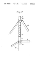
- FIG. 17 shows the joints of the members in the fourth embodiment of the present invention.
- FIG. 18 shows the fourth embodiment of the present invention as deployed
- FIG. 19 schematically shows a basic module of an expandable truss structure according to a fifth embodiment of the present invention.
- FIG. 20 schematically shows the basic module shown in FIG. 19 as deployed.
- FIG. 21 schematically shows an expandable truss structure in a deployed state which is formed by combining together a plurality of basic modules of the type shown in FIG. 19.
- reference numerals 3a, 3b denote first couplers each having a pin joint portion, 3c second couplers which are respectively secured to ends of ribs, which ends define free ends of the expandable truss structure, 10 stems each having a coupler 3a secured to one end thereof, and each pair of adjacent stems 10 being disposed in such a manner that their axes extend in opposite directions.
- the numeral 11 denotes a main slide hinge which slides on each stem 10, and 12 ribs pinned at first ends thereof to the main slide hinge 11 so as to extend radially therefrom, the ribs 12 being deployable at right angles to the axis of the stem 10, and the second end of each rib 12 being pinned to a first coupler 3b which is secured to an adjacent inverted stem 10 in an inverted relationship with the first coupler 3a on said stem 10.
- Those ends of the ribs 12 which define free ends of the expandable truss structure are connected to the second couplers 3c, respectively.
- the numeral 13 denotes wires which are disposed between the first couplers 3a, 3b that are secured to the ends of the stems 10, between the second couplers 3c disposed at the free ends of the expandable truss structure and between the first and second couplers 3a, 3b and 3c, the wires 13 being set so that they are pulled when the expandable truss structure is deployed.
- the reference numeral 14 denotes a stopper defined by a coil spring which is provided on the other or second end of the stem 10, and 15 a lock pin which is provided at a position on the stem 10 where the min slide hinge 11 is to be looked, the lock pin 15 being biased to project outward from the stem 10 by a spring (not shown) which is interposed between the inside of the stem 10 and the lock pin 15 so that the lock pin 15 engages with a pin groove 16 provided in the main slide hinge 11.
- ⁇ is the angle between the stem 11 and each rib 12 the angle ⁇ being set so as to be about 90° when the expandable truss structure is deployed.
- FIG. 9 shows the expandable truss structure according to the first embodiment as deployed.
- the triangle which is defined by the following three vertices when the structure is deployed, i.e., a first coupler on a stem 10, for example, a coupler 3a, the main slide hinge 11 on the stem 10 and another coupler, for example, a coupler 3b, connected to the second end of a rib 12 which is pinned at its first end to the main slide hinge 11, is deformed, and the angle ⁇ between the rib 12 and the stem 10 shown in FIG. 8 is zero.
- the distance from the coupler 3a to the main slide hinge 11 increases, whereas the distance from the coupler 3a to the other coupler 3b is maintained within a predetermined length by means of the wire 13. Since the distance from the coupler 3b to the main slide hinge 11 is also maintained at an amount equivalent to the length of the rib 12, the triangle that is defined by the above-described three vertices is formed, and the angle ⁇ between the rib 12 and the stem 10 increases.
- the distance from the coupler 3b to a still further coupler, for example, a coupler 3c, which is provided at the second end of another rib 12 pinned at its first end to the above-described main slide hinge 11 also increases.
- the main slide hinge 11 reaches a predetermined lock position, the wires 13 extending between the couplers 3a and 3b and those between the couplers 3b and 3c are tensely stretched.
- the lock pin 15 provided on the stem 10 engages with the pin groove 16 provided in the main slide hinge 11, and the main slide hinge 11 abuts against the stopper 14.
- the main slide hinge 11 receives counterforce from the stopper 14 and is thereby pressed against the lock pin 15.
- the expandable truss structure is maintained in the deployed configuration.
- tension is applied to the wires 13, and compressive force which equilibrates this tension is applied to the stem 10 and the ribs 12.
- compressive force which equilibrates this tension is applied to the stem 10 and the ribs 12.
- FIG. 10 which shows an expandable truss structure according to a second embodiment of the present invention in a deployed state
- reference numeral 17 denotes a synchronous slide hinge which slides on each stem 10 between the coupler 3 and the main slide hinge 11, and 18 a synchronous beam which is pinned at one end thereof to the synchronous slide hinge 17 and at the other end to an intermediate portion of each rib 12.
- FIG. 11 is an enlarged view of the portion D of FIG. 10, in which reference numeral 19 denotes a compression spring.
- FIG. 12 shows the expandable truss structure according to the second embodiment as deployed.
- reference numerals 3 and 10 to 16 denote the same elements as those with these reference numerals shown in FIGS. 7 to 9.
- this expandable truss structure has the advantages that no external energy is needed for deployment and highly reliable deployment is possible without fear of the wires 13 becoming entangled with each other, which phenomenon is likely to occur in the case of a synchronous deployment.
- synchronous beams for effecting synchronous deployment and a compression spring which supplies energy for deployment are incorporated between each stem and the associated ribs. Therefore, reliability in deployment is enhanced and deployment is attained without the aid of external force.
- FIG. 13 shows an expandable truss structure according to a third embodiment of the present invention which is in a deployed state.
- reference numerals 3a and 3b denote first couplers each having a pin joint portion, 3c second couplers which are respectively secured to those ends of the ribs provided which define free ends of the expandable truss structure, and 10 stems each having a coupler 3a secured to one end thereof, each pair of adjacent stems 10 being disposed in such a manner that their axes extend in opposite directions.
- Numeral 11 denotes a main slide hinge which slides on each stem 10, and 12 ribs pinned at first ends thereof to the main slide hinge 11 such as to extend radially therefrom, the ribs 12 being deployable at right angles to the axis of the stem 10, and the second end of each rib 12 being pinned to a first coupler 3b which is secured to an adjacent inverted stem 10 in an inverted relationship with the first coupler 3a on said stem 10.
- Those ends of the ribs 12 which define free ends of the expandable truss structure are connected to the second couplers 3c, respectively.
- the numeral 13 denotes wires which are disposed between the first couplers 3a, 3b that are secured to the ends of the stems 10, between the second couplers 3c disposed at the free ends of the expandable truss structure, and between the first and second couplers 3a and 3c, the wires 13 being set so that they are pulled when the expandable truss structure is deployed.
- the reference numeral 20 denotes a synchronous slide hinge which slides on each stem 10 between the coupler 3a and the main slide hinge 11, and 21 a synchronous cable which is connected at one end thereof to the synchronous slide hinge 20 and at the other end to a coupler 3a provided on a stem 10 which is disposed adjacent and in an inverted relationship with said stem 10.
- numeral 22 denotes diagonal members connecting together the couplers 3a on the top surface side and the couplers 3b, 3c on the bottom surface side by means of pins.
- FIG. 14 is an enlarged view of the portion C of FIG.
- ⁇ is the angle between the stem 11 and each rib 12 the angle ⁇ being set so as to be about 90° when the expandable truss structure is deployed.
- the triangle which is defined by the following three vertices when the structure is deployed, i.e., a coupler on a stem 10, for example, a coupler 3a the main slide hinge 11 on the stem 10 and another coupler, for example, a coupler 3b, connected to the second end of a rib 12 which is pinned at its first end to the main slide hinge 11, is deformed, and the angle ⁇ between the rib 12 and the stem 10 shown in FIG. 14 is zero.
- Deployment is effected by pushing the main slide hinge 11 and the synchronous slide hinge 20 away from each other by means of the resilient force of the coil spring 24.
- the distance from the coupler 3a on the stem 10 to the main slide hinge 11 increases.
- the distance from the coupler 3a to the coupler 3b is maintained at a predetermined length by means of the diagonal member 22. Since the distance from the coupler 3b to the main slide hinge 11 is also maintained at an amount equivalent to the length of the rib 12, the triangle that is defined by the above-described three vertices is deployed, and the angel ⁇ between the rib 12 and the stem 10 increases.
- the distance from the coupler 3b to a still further coupler, for example, a coupler 3c, which is provided at the second end of another rib 12 pinned at its first end to the above-described main slide hinge 11 also increases.
- the wires 13 extending between the couplers 3a on the top surface side, between the couplers 3b, 3c on the bottom surface side and between the couplers 3a at the free ends of the top surface and the couplers 3c at the free ends of the bottom surface are tensely stretched.
- the wires 13 are continuously stretched out until the main slide hinge 11 abuts against the stopper 23.
- FIG. 15 shows the expandable truss structure according to the third embodiment of the present invention which is being deployed.
- synchronous cables for effecting synchronous deployment and a coil spring for supplying energy for deployment are incorporated between each stem and the associated ribs. Therefore, reliability in deployment is enhanced and deployment is attained without the aid of external force. Further, since the forces from the synchronous cables act on the couplers, no bending moment is generated in the ribs, and it is therefore possible to achieve a reduction in the weight of the ribs.
- FIG. 16 shows an expandable truss structure according to a fourth embodiment of the present invention which is in a deployed state.
- the reference numerals 3a and 3b denote first couplers each having a pin joint portion, 3c second couplers which are respectively secured to those ends of ribs which define free ends of the expandable truss structure, 10 stems each having a coupler 3a or 3b secured to one end thereof, each pair of adjacent stems 10 being disposed in such a manner that their axes extend in opposite directions.
- the numeral 11 denotes a main slide hinge which slides on each stem 10, and 12 ribs pinned at first ends thereof to the main slide hinge 11 so as to extend radially therefrom, the ribs 12 being deployable at right angles to the axis of the stem 10, and the second end of each rib 12 being pinned to a coupler 3b which is secured to an adjacent inverted stem 10 in inverse relation to the coupler 3a on said stem 10.
- Those ends of the ribs 12 which define free ends of the expandable truss structure are connected to the second couplers 3c, respectively.
- the numeral 13 denotes wires which are disposed between the couplers 3a, 3b secured to the ends of the stems 10, between the second couplers 3c disposed at the free ends of the expandable truss structure and between the first couplers 3a which are disposed at the peripheral portion of the structure and the second couplers 3c, the wires 13 being set so that they are pulled when the expandable truss structure is deployed.
- Reference numeral 22 denotes diagonal members connecting together the couplers 3a on the top surface side and the couplers 3b, 3c on the bottom surface side by means of pins, 20 a synchronous slide hinge which slides on each stem 10 between the coupler 3 and the main slide hinge 11 and 25 a synchronous beam which is pinned at one end thereof to the synchronous slide hinge 20 and at the other end to an intermediate portion of each rib 12.
- FIG. 17 is an enlarged view of the portion C of FIG.
- reference numeral 23 denotes a stopper which defines the bottom dead centre point of the main slide hinge 11 when the structure is deployed
- 24 a coil spring which provides driving force for deploying the expandable truss structure according to the present invention
- ⁇ is the angle between the stem 11 and each rib 12, the angle ⁇ being set so as to be about 90° when the expandable truss structure is deployed.
- the triangle which is defined by the following three vertices when the structure is deployed, i.e., a coupler on a stem 10, for example, a coupler 3a, the main slide hinge 11 on the stem 10 and another coupler, for example, a coupler 3b, connected to the second end of a rib 12 which is pinned at its first end to the main slide hinge 11, is deformed, and the angle ⁇ between the rib 12 and the stem 10 shown in FIG. 17 is zero.
- Deployment is effected by pushing the main slide hinge 11 and the synchronous slide hinges 20 away from each other by means of the resilient force of the coil spring 24.
- the distance from the coupler 3a on the stem 10 to the main slide hinge 11 increases.
- the distance from the coupler 3a to the coupler 3b is maintained at a predetermined length by means of the diagonal member 22. Since the distance from the coupler 3b to the main slide hinge 11 is also maintained at an amount equivalent to the length of the rib 12, the triangle that is defined by the above-described three vertices is deployed, and the angle ⁇ between the rib 12 and the stem 10 increases.
- the distance from the coupler 3b to a still further coupler, for example, a coupler 3c, which is provided at the second end of another rib 12 which is pinned at its first end to the above-described main slide hinge 11 also increases.
- the wires 13 extending between the couplers 3a on the top surface side, between the couplers 3b, 3c on the bottom surface side and between the couplers 3a at the free ends of the top surface and the couplers 3c at the free ends of the bottom surface are tensely stretched.
- the wires 13 are continuously stretched out until the main slide hinge 11 abuts against the stopper 23. Since the wires 13 thus stretched cause the couplers 3a, 3b and 3c to be pressed toward the ribs 12, there is no looseness at the pin joints, and the expandable truss structure hence becomes highly rigid.
- FIG. 18 shows the expandable truss structure according to the fourth embodiment of the present invention as deployed.
- synchronous beams for effecting synchronous deployment and a coil spring for supplying energy for deployment are incorporated between each stem and the associated ribs. Therefore, reliability in deployment is enhanced and deployment is attained without the aid of external force.
- FIG. 19 shows a basic module of an expandable truss structure according to a fifth embodiment of the present invention, the module being in a deployed state.
- reference numerals 3a, 3b and 3c respectively denote first, second and third couplers each having a joint portion, 3d a fourth coupler, 10 a stem having the first and second couplers 3a, 3b secured to both ends thereof, and 26 four ribs having the same length, each rib 26 being pinned at both ends thereof to second and third couplers 3b, 3c, respectively, and deployable in a direction perpendicular to the axis of the stem 10 when the expandable truss structure is deployed.
- the numeral 27 denotes first tension members having the same length which are tensely stretched between the first and third couplers 3a, 3c when the structure is deployed, 28 second tension members having the same length each of which is tensely stretched between each pair of adjacent third couplers 3c when the structure is deployed, 29 a spring having both ends thereof connected to the second and fourth couplers 3b, 3d, and 30 third tension members having the same length which are tensely stretched between the third and fourth couplers 3c, 3d when the structure is deployed.
- the force of the spring 29 is transmitted to the various members through the third tension members 30 to apply deploying force to the basic unit of the expandable truss structure.
- compressive force is imposed on the joints of the stem 10 and the ribs 26 by applying tension to the first and second tension members 27, 28, thereby eliminating looseness from the pin joint portion of each coupler 3.
- FIG. 20 shows the above-described basic module of a expandable truss structure as deployed.
- the first and second tension members 27, 28 that have flexibility are not tense but bend under their own weight.
- FIG. 21 shows an expandable truss structure formed by combining a plurality of basic modules of the type described above, the structure being in a deployed state.
- these modules are connected together by sharing one first tension member 27 in such a manner that the first coupler 3a of one of the modules defines one of the third couplers 3c of the other.
- these modules are connected together in such a manner as to share two third couplers 3c and one second tension member 28.
- the first and third couplers 3a, 3c are identical with each other.
- the stem 10 and the ribs 26 of the basic module of an expandable truss structure are closer to each other than in the state shown in FIG. 20, the angle made therebetween being substantially zero, and the spring 29 is in its maximum compressed state.
- the ribs 29 are biased so as to be deployed by the force of the spring 29 which is transmitted thereto through the third tension members 30 and the third couplers 3c.
- each pair of adjacent basic modules which are in the packaged state are disposed in such a manner that their respective stems 10 extend in opposite directions.
- the height of the truss structure in the axial direction of the stem 10 is the sum total of heights of the stem 10 and the spring 29.
- the deploying force supplied by the spring 29 causes the ribs 26 to pivot so as to extend radially in a direction perpendicular to the axis of the stem 10, so that the angle between the stem 10 and each rib 26 becomes substantially 90°.
- the tens-on applied to the first and second tension members the compressive force applied to the stem 10 and the ribs 26, the tension applied to the third tension members and the spring force equilibrate each other and, in this state, the deployed configuration of the structure is maintained.
- the fifth embodiment of the present invention it is possible to obtain high rigidity with ease since a tension member is tensely stretched between each pair of adjacent vertices o each polyhedral module to achieve a structure having no looseness.
- a spring or the like is incorporated as the source of the energy utilized in deployment, the module is deployable without the aid of any external force.
Landscapes
- Physics & Mathematics (AREA)
- Electromagnetism (AREA)
- Engineering & Computer Science (AREA)
- Architecture (AREA)
- Civil Engineering (AREA)
- Structural Engineering (AREA)
- Aerials With Secondary Devices (AREA)
- Rod-Shaped Construction Members (AREA)
Applications Claiming Priority (8)
| Application Number | Priority Date | Filing Date | Title |
|---|---|---|---|
| JP62117470A JPS63284334A (ja) | 1987-05-14 | 1987-05-14 | 展開トラス構造物 |
| JP62-117470 | 1987-05-14 | ||
| JP62-169120 | 1987-07-07 | ||
| JP16912087A JPS6414448A (en) | 1987-07-07 | 1987-07-07 | Expansion truss structure |
| JP62-169119 | 1987-07-07 | ||
| JP62169119A JPS6414447A (en) | 1987-07-07 | 1987-07-07 | Expansion truss structure |
| JP62-170006 | 1987-07-08 | ||
| JP62170006A JPH0617605B2 (ja) | 1987-07-08 | 1987-07-08 | 展開トラス構造物 |
Publications (1)
| Publication Number | Publication Date |
|---|---|
| US5014484A true US5014484A (en) | 1991-05-14 |
Family
ID=27470434
Family Applications (1)
| Application Number | Title | Priority Date | Filing Date |
|---|---|---|---|
| US07/165,518 Expired - Fee Related US5014484A (en) | 1987-05-14 | 1988-03-08 | Module for expandable truss structure and expandable truss structure employing said module |
Country Status (4)
| Country | Link |
|---|---|
| US (1) | US5014484A (fr) |
| EP (1) | EP0290729B1 (fr) |
| CA (1) | CA1295452C (fr) |
| DE (1) | DE3852566T2 (fr) |
Cited By (19)
| Publication number | Priority date | Publication date | Assignee | Title |
|---|---|---|---|---|
| US5148648A (en) * | 1991-06-21 | 1992-09-22 | Skyline Displays, Inc. | Quick-release frame connector |
| US5230196A (en) * | 1990-09-05 | 1993-07-27 | World Shelters, Inc. | Polyhedron building system |
| US5243803A (en) * | 1988-07-05 | 1993-09-14 | Mitsubishi Denki Kabushiki Kaisha | Module for expandable framework structure and expandable framework structure employing said module |
| US5444946A (en) * | 1993-11-24 | 1995-08-29 | World Shelters, Inc. | Portable shelter assemblies |
| US5931420A (en) * | 1997-02-24 | 1999-08-03 | Mitsubishi Denki Kabushiki Kaisha | Deployable truss structure |
| US6038736A (en) * | 1998-06-29 | 2000-03-21 | Lockheed Martin Corporation | Hinge for deployable truss |
| US6062527A (en) * | 1998-06-29 | 2000-05-16 | Lockheed Martin Corporation | Flexurally hinged tripod support boom |
| US6076770A (en) * | 1998-06-29 | 2000-06-20 | Lockheed Martin Corporation | Folding truss |
| US6313811B1 (en) | 1999-06-11 | 2001-11-06 | Harris Corporation | Lightweight, compactly deployable support structure |
| US6618025B2 (en) | 1999-06-11 | 2003-09-09 | Harris Corporation | Lightweight, compactly deployable support structure with telescoping members |
| US7107733B1 (en) * | 1999-08-25 | 2006-09-19 | Gerhard Rueckert | Deployable structure with modular configuration consisting of at least one collapsible module |
| US20060272266A1 (en) * | 2005-05-12 | 2006-12-07 | Trott Charles R | Modular structure |
| WO2008009064A1 (fr) * | 2006-07-21 | 2008-01-24 | First Green Park Pty Ltd | Structures de panneaux |
| CN102623787A (zh) * | 2011-01-31 | 2012-08-01 | 日本电气东芝太空系统株式会社 | 可展开天线 |
| US8381460B1 (en) * | 2007-02-27 | 2013-02-26 | Patrick P. McDermott | Extendable beam structure (EBS) |
| US10060119B2 (en) * | 2014-07-01 | 2018-08-28 | Dsm Ip Assets B.V. | Structures having at least one polymeric fiber tension element |
| US20190078331A1 (en) * | 2017-09-14 | 2019-03-14 | Christine Inez Karstens | Expandable Sustainable Member Beam and Pattern |
| US20220112706A1 (en) * | 2020-10-12 | 2022-04-14 | Jacob Eisenberg | Strata space frame |
| DE102024106226A1 (de) * | 2024-03-05 | 2025-09-11 | Schaeffler Technologies AG & Co. KG | Vorrichtung für akustische Prüfungen |
Families Citing this family (5)
| Publication number | Priority date | Publication date | Assignee | Title |
|---|---|---|---|---|
| GB2256444A (en) * | 1991-05-25 | 1992-12-09 | Robert Laxton John Burdon | Foldable structure |
| US5864324A (en) * | 1996-05-15 | 1999-01-26 | Trw Inc. | Telescoping deployable antenna reflector and method of deployment |
| US6028570A (en) * | 1998-05-18 | 2000-02-22 | Trw Inc. | Folding perimeter truss reflector |
| US6225965B1 (en) * | 1999-06-18 | 2001-05-01 | Trw Inc. | Compact mesh stowage for deployable reflectors |
| CN108666733B (zh) * | 2018-05-15 | 2020-06-09 | 西安空间无线电技术研究所 | 一种网状天线网面管理机构及管理方法 |
Citations (10)
| Publication number | Priority date | Publication date | Assignee | Title |
|---|---|---|---|---|
| US319225A (en) * | 1885-06-02 | gilabdini | ||
| GB189418418A (en) * | 1894-09-28 | 1895-08-31 | George Bertram Ross | Improvements in Automatic or Self-opening Umbrellas and the like. |
| US570857A (en) * | 1896-11-03 | Umbrella | ||
| US808863A (en) * | 1905-03-11 | 1906-01-02 | Michael G Mcguire | Umbrella. |
| US2534710A (en) * | 1946-05-08 | 1950-12-19 | Serge E Golian | Buoy supported collapsible radar reflector |
| DE1900443A1 (de) * | 1969-01-04 | 1970-07-16 | Bauermann & Soehne Gmbh | Selbstoeffnender,vorzugsweise verkuerzbarer Schirm |
| US4475323A (en) * | 1982-04-30 | 1984-10-09 | Martin Marietta Corporation | Box truss hoop |
| US4532742A (en) * | 1982-10-09 | 1985-08-06 | Mitsubishi Denki Kabushiki Kaisha | Extendible structure |
| US4534374A (en) * | 1984-02-08 | 1985-08-13 | Day San Tong | Fully automatic single push button type umbrella |
| US4667451A (en) * | 1985-07-25 | 1987-05-26 | Fuji Jukogyo Kabushiki Kaisha | Collapsible truss unit, and frameworks constructed by combinations of such units |
Family Cites Families (2)
| Publication number | Priority date | Publication date | Assignee | Title |
|---|---|---|---|---|
| US3152329A (en) * | 1961-09-11 | 1964-10-06 | Chemring Ltd | Collapsible octahedral corner reflector |
| US3771274A (en) * | 1972-05-30 | 1973-11-13 | Gen Dynamics Corp | Expandable retractable structure |
-
1988
- 1988-03-02 CA CA000560368A patent/CA1295452C/fr not_active Expired - Lifetime
- 1988-03-02 DE DE3852566T patent/DE3852566T2/de not_active Expired - Fee Related
- 1988-03-02 EP EP88103180A patent/EP0290729B1/fr not_active Expired - Lifetime
- 1988-03-08 US US07/165,518 patent/US5014484A/en not_active Expired - Fee Related
Patent Citations (10)
| Publication number | Priority date | Publication date | Assignee | Title |
|---|---|---|---|---|
| US319225A (en) * | 1885-06-02 | gilabdini | ||
| US570857A (en) * | 1896-11-03 | Umbrella | ||
| GB189418418A (en) * | 1894-09-28 | 1895-08-31 | George Bertram Ross | Improvements in Automatic or Self-opening Umbrellas and the like. |
| US808863A (en) * | 1905-03-11 | 1906-01-02 | Michael G Mcguire | Umbrella. |
| US2534710A (en) * | 1946-05-08 | 1950-12-19 | Serge E Golian | Buoy supported collapsible radar reflector |
| DE1900443A1 (de) * | 1969-01-04 | 1970-07-16 | Bauermann & Soehne Gmbh | Selbstoeffnender,vorzugsweise verkuerzbarer Schirm |
| US4475323A (en) * | 1982-04-30 | 1984-10-09 | Martin Marietta Corporation | Box truss hoop |
| US4532742A (en) * | 1982-10-09 | 1985-08-06 | Mitsubishi Denki Kabushiki Kaisha | Extendible structure |
| US4534374A (en) * | 1984-02-08 | 1985-08-13 | Day San Tong | Fully automatic single push button type umbrella |
| US4667451A (en) * | 1985-07-25 | 1987-05-26 | Fuji Jukogyo Kabushiki Kaisha | Collapsible truss unit, and frameworks constructed by combinations of such units |
Non-Patent Citations (4)
| Title |
|---|
| John A. Fager & Ray Garriott, "Large Aperture Expandable Truss Microwave Antenna", 1969. |
| John A. Fager & Ray Garriott, Large Aperture Expandable Truss Microwave Antenna , 1969. * |
| W. Schneider, "Space Station Structures", 1984. |
| W. Schneider, Space Station Structures , 1984. * |
Cited By (24)
| Publication number | Priority date | Publication date | Assignee | Title |
|---|---|---|---|---|
| US5243803A (en) * | 1988-07-05 | 1993-09-14 | Mitsubishi Denki Kabushiki Kaisha | Module for expandable framework structure and expandable framework structure employing said module |
| US5230196A (en) * | 1990-09-05 | 1993-07-27 | World Shelters, Inc. | Polyhedron building system |
| US5148648A (en) * | 1991-06-21 | 1992-09-22 | Skyline Displays, Inc. | Quick-release frame connector |
| US5444946A (en) * | 1993-11-24 | 1995-08-29 | World Shelters, Inc. | Portable shelter assemblies |
| US5931420A (en) * | 1997-02-24 | 1999-08-03 | Mitsubishi Denki Kabushiki Kaisha | Deployable truss structure |
| US6038736A (en) * | 1998-06-29 | 2000-03-21 | Lockheed Martin Corporation | Hinge for deployable truss |
| US6062527A (en) * | 1998-06-29 | 2000-05-16 | Lockheed Martin Corporation | Flexurally hinged tripod support boom |
| US6076770A (en) * | 1998-06-29 | 2000-06-20 | Lockheed Martin Corporation | Folding truss |
| US6313811B1 (en) | 1999-06-11 | 2001-11-06 | Harris Corporation | Lightweight, compactly deployable support structure |
| US6618025B2 (en) | 1999-06-11 | 2003-09-09 | Harris Corporation | Lightweight, compactly deployable support structure with telescoping members |
| US7107733B1 (en) * | 1999-08-25 | 2006-09-19 | Gerhard Rueckert | Deployable structure with modular configuration consisting of at least one collapsible module |
| US20060272266A1 (en) * | 2005-05-12 | 2006-12-07 | Trott Charles R | Modular structure |
| WO2008009064A1 (fr) * | 2006-07-21 | 2008-01-24 | First Green Park Pty Ltd | Structures de panneaux |
| US8381460B1 (en) * | 2007-02-27 | 2013-02-26 | Patrick P. McDermott | Extendable beam structure (EBS) |
| CN102623787A (zh) * | 2011-01-31 | 2012-08-01 | 日本电气东芝太空系统株式会社 | 可展开天线 |
| US20120193498A1 (en) * | 2011-01-31 | 2012-08-02 | Japan Aerospace Exploration Agency | Deployable antenna |
| US8922456B2 (en) * | 2011-01-31 | 2014-12-30 | Nec Toshiba Space Systems, Ltd. | Deployable antenna |
| CN102623787B (zh) * | 2011-01-31 | 2016-02-17 | 日本电气太空技术株式会社 | 可展开天线 |
| US10060119B2 (en) * | 2014-07-01 | 2018-08-28 | Dsm Ip Assets B.V. | Structures having at least one polymeric fiber tension element |
| US20190078331A1 (en) * | 2017-09-14 | 2019-03-14 | Christine Inez Karstens | Expandable Sustainable Member Beam and Pattern |
| US10501937B2 (en) * | 2017-09-14 | 2019-12-10 | Christine Inez Karstens | Expandable sustainable member beam and pattern |
| US20220112706A1 (en) * | 2020-10-12 | 2022-04-14 | Jacob Eisenberg | Strata space frame |
| US11680398B2 (en) * | 2020-10-12 | 2023-06-20 | Jacob Eisenberg | Strata space frame |
| DE102024106226A1 (de) * | 2024-03-05 | 2025-09-11 | Schaeffler Technologies AG & Co. KG | Vorrichtung für akustische Prüfungen |
Also Published As
| Publication number | Publication date |
|---|---|
| EP0290729A3 (fr) | 1991-04-10 |
| EP0290729A2 (fr) | 1988-11-17 |
| DE3852566T2 (de) | 1995-08-31 |
| CA1295452C (fr) | 1992-02-11 |
| DE3852566D1 (de) | 1995-02-09 |
| EP0290729B1 (fr) | 1994-12-28 |
Similar Documents
| Publication | Publication Date | Title |
|---|---|---|
| US5014484A (en) | Module for expandable truss structure and expandable truss structure employing said module | |
| US5040349A (en) | Collapsible truss structures | |
| US3496687A (en) | Extensible structure | |
| US6550209B2 (en) | Modular deployable antenna | |
| US4819399A (en) | Deployable truss | |
| EP0408826B1 (fr) | Mât extensible | |
| US5163262A (en) | Collapsible structure | |
| US8434196B1 (en) | Multi-axis compliant hinge | |
| US4604844A (en) | Deployable M-braced truss structure | |
| CN115871958B (zh) | 空间可展单元、平面可展天线支撑桁架和航天器 | |
| US12583628B2 (en) | Deployable, ultra-stowable truss for space applications | |
| Onoda | Two-dimensional deployable truss structures for space applications | |
| KR102264913B1 (ko) | 평면 형태로 수납 가능한 전개형 트러스 붐 구조물 | |
| JPH0659880B2 (ja) | 展開式骨組構造物 | |
| JPH02283597A (ja) | 展開型トラス構造及びその展開同期装置 | |
| JPH0569759B2 (fr) | ||
| JPH01208298A (ja) | 展開トラス構造物 | |
| JPH02136396A (ja) | 展開トラスアンテナ | |
| Khaliulin et al. | A Transformed Framework with a Folded Configuration | |
| JPH01127498A (ja) | 展開トラス構造物 | |
| JPH02136398A (ja) | 展開トラスアンテナ | |
| JPH0479501A (ja) | 展開トラスアンテナ | |
| JPH02230803A (ja) | 展開トラスアンテナ | |
| JPH0617605B2 (ja) | 展開トラス構造物 | |
| JPH03143004A (ja) | 展開トラスアンテナ |
Legal Events
| Date | Code | Title | Description |
|---|---|---|---|
| AS | Assignment |
Owner name: MITSUBISHI DENKI KABUSHIKI KAISHA, 2-3, MARUNOUCHI Free format text: ASSIGNMENT OF ASSIGNORS INTEREST.;ASSIGNORS:TANIZAWA, KAZUO;NAKAGAWA, JUN;REEL/FRAME:004865/0988 Effective date: 19880219 Owner name: MITSUBISHI DENKI KABUSHIKI KAISHA,JAPAN Free format text: ASSIGNMENT OF ASSIGNORS INTEREST;ASSIGNORS:TANIZAWA, KAZUO;NAKAGAWA, JUN;REEL/FRAME:004865/0988 Effective date: 19880219 |
|
| FEPP | Fee payment procedure |
Free format text: PAYOR NUMBER ASSIGNED (ORIGINAL EVENT CODE: ASPN); ENTITY STATUS OF PATENT OWNER: LARGE ENTITY |
|
| REMI | Maintenance fee reminder mailed | ||
| LAPS | Lapse for failure to pay maintenance fees | ||
| FP | Lapsed due to failure to pay maintenance fee |
Effective date: 19950517 |
|
| STCH | Information on status: patent discontinuation |
Free format text: PATENT EXPIRED DUE TO NONPAYMENT OF MAINTENANCE FEES UNDER 37 CFR 1.362 |