US5042437A - Rocker arm arrangement for variable timing valve train - Google Patents
Rocker arm arrangement for variable timing valve train Download PDFInfo
- Publication number
- US5042437A US5042437A US07/606,966 US60696690A US5042437A US 5042437 A US5042437 A US 5042437A US 60696690 A US60696690 A US 60696690A US 5042437 A US5042437 A US 5042437A
- Authority
- US
- United States
- Prior art keywords
- rocker arm
- cam
- cam follower
- engine
- bore
- Prior art date
- Legal status (The legal status is an assumption and is not a legal conclusion. Google has not performed a legal analysis and makes no representation as to the accuracy of the status listed.)
- Expired - Fee Related
Links
Images



Classifications
-
- F—MECHANICAL ENGINEERING; LIGHTING; HEATING; WEAPONS; BLASTING
- F01—MACHINES OR ENGINES IN GENERAL; ENGINE PLANTS IN GENERAL; STEAM ENGINES
- F01L—CYCLICALLY OPERATING VALVES FOR MACHINES OR ENGINES
- F01L1/00—Valve-gear or valve arrangements, e.g. lift-valve gear
- F01L1/26—Valve-gear or valve arrangements, e.g. lift-valve gear characterised by the provision of two or more valves operated simultaneously by same transmitting-gear; peculiar to machines or engines with more than two lift-valves per cylinder
- F01L1/267—Valve-gear or valve arrangements, e.g. lift-valve gear characterised by the provision of two or more valves operated simultaneously by same transmitting-gear; peculiar to machines or engines with more than two lift-valves per cylinder with means for varying the timing or the lift of the valves
-
- F—MECHANICAL ENGINEERING; LIGHTING; HEATING; WEAPONS; BLASTING
- F02—COMBUSTION ENGINES; HOT-GAS OR COMBUSTION-PRODUCT ENGINE PLANTS
- F02B—INTERNAL-COMBUSTION PISTON ENGINES; COMBUSTION ENGINES IN GENERAL
- F02B1/00—Engines characterised by fuel-air mixture compression
- F02B1/02—Engines characterised by fuel-air mixture compression with positive ignition
- F02B1/04—Engines characterised by fuel-air mixture compression with positive ignition with fuel-air mixture admission into cylinder
Definitions
- the present invention relates generally to an engine valve train and more specifically to a variable valve timing arrangement which permits the lift and/or timing of the valves to be selectively varied.
- JP-A-63-167016 and JP-A-63-57805 disclose rocker arm arrangements which include a main rocker arm which cooperates with a low speed cam and a sub-rocker arm which cooperates with a high speed cam.
- the two rocker arms are pivotally mounted on a common rocker arm shaft.
- a hydraulically operated connection or interlocking device which enables the main and sub-rocker arms to be selectively locked together, comprises a set of plunger bores which are formed in the rocker arms in a manner to be parallel with and at a predetermined distance from, the axis of the shaft about which the arms are commonly pivotal.
- a further problem come in that, if a so called partial cam is used and the hydraulic control system malfunctions in a manner wherein an adequate level of hydraulic pressure cannot be supplied to the interlocking device, the amount of torque produced by the engine falls to a level wherein vehicle drivability is badly deteriorated.
- the above object is achieved by an arrangement wherein, in the absence of sufficient hydraulic pressure to operate the interlocking mechanisms which switch the valve lift control from one cam follower to another, it defaults to a cam follower suited for low speed engine operation rather than one which is adapted to maximize fuel economy.
- the initial low speed cam follower defaulting improves aspiration and reduces the tendency for incomplete combustion to induce the formation of smouldering deposits on the spark plug electrodes.
- the defaulting enable the engine to produce enough torque to render the vehicle drivable.
- a first aspect of the invention comes in an internal combustion engine which features: a cam shaft having first, second and third cams; a rocker arm; a first cam follower which is reciprocatively mounted on the rocker arm and arranged to engage the first cam; a first interlocking device for selectively locking the first cam follower to the rocker arm and preventing relative movement therebetween in response to a first hydraulic signal having a first predetermined level; a second cam follower which is reciprocatively mounted on the rocker arm and arranged to engage the second cam; a second interlocking device for selectively locking the second cam to the rocker arm and preventing relative movement therebetween in response to the absence of a second hydraulic signal having a second predetermined level; and a third cam follower which is fixedly mounted on the rocker arm and arranged to engage the third cam.
- a second aspect of the invention comes in an internal combustion engine which features: a cam shaft; first, second and third cams on the cam shaft, the first cam being adapted to produce valve lift suited for high speed engine operation, the second cam being adapted to produce valve lift suited from low engine speed operation and the third cam being adapted to produce partial lift which is suited for optimizing fuel economy; a rocker arm; a first cam follower which engages the first cam and which is relatively movable with respect to the rocker arm; a first interlocking device which normally permits relative movement between the first cam follower and the rocker arm, the first interlocking device locking the first cam follower to the rocker arm and preventing relative movement therebetween in response to a first predetermined hydraulic signal; a second cam follower engages the second cam and which is relatively movable with respect to the rocker arm; a second interlocking device which normally locks the second cam follower to the rocker arm and prevents relative movement therebetween, the second interlocking device releasing the second cam follower and permitting relative movement between the second
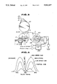
- FIG. 1 is a plan view partially in section showing the construction which characterizes a first embodiment of the present invention
- FIG. 2 is a similar plan view wherein the sectioning has been omitted and which shows the disposition of the cam three followers utilized;
- FIG. 3 is an elevational view of the embodiment shown in FIGS. 1 and 2;
- FIG. 4 is a graph which shows in terms of valve lift crank angle the valve lift characteristics provided by the partial cam, low speed cam and the high speed cam, during exhaust and induction modes;
- FIG. 5 is a map which shows in terms of engine speed and engine torque, the three zones for which the, partial, low and high speed cams are used;
- FIG. 6 is a table which shows the level to which the hydraulic pressure in the control lines which lead to the two interlocking devices utilized in the embodiment of the invention, are controlled for each of the above mentioned three engine operational zones;
- FIGS. 7 to 10 are charts which show the various operational characteristics which are derived with the embodiment and how said characteristics vary with changes in valve timing/overlap.
- FIGS. 1 to 3 show a rocker arm arrangement according to an embodiment of the present invention.
- this rocker arm 1 is arranged to simultaneously lift two poppet valves 9 which can be associated with either the induction or exhaust system of an internal combustion engine.
- the rocker arm is formed so as to be essentially square as seen in plan and is pivotally mounted on a rocker shaft 3 which is rigidly supported on a cylinder head (not shown).
- Valve engagement portions 10 which project from the two corners of the arm are arranged to engage the tops of the stems of valves 9 in the manner best seen in FIG. 3.
- a first cam follower 4 is fixedly connected the upper surface of the rocker arm 1 (e.g. formed integrally with the rocker arm). This follower is arranged to engage a "partial" cam 21 which has a profile of the nature shown in FIG. 3 and which is designed to produce relatively small lift characteristics.
- Second and third relatively displaceable cam followers 5 and 6 are reciprocatively mounted in suitable bores formed in the rocker arm 1 and arranged to engage low speed and high speed cams 22, 23 which have profiles designed to produce lift characteristics suited for low and high speed engine operation, respectively.
- Each of the first, second and third cams 21, 22 and 23 are provided (integrally formed) on a single cam shaft 20 and are arranged in a manner to directly engage the respective followers 4, 5 and 6.
- the lift characteristics provided by these cams is illustrated in FIG. 4.
- the cam followers and the bores in which they are respectively received have rectangular cross-sections.
- the bores or cylinders (as they will be referred to hereinafter) are formed in a manner that the center lines thereof pass through the axis of rotation of the cam shaft 20 when the cam followers 4-6 are in engagement which the base circles of the cams 21-23. This arrangement promotes smooth reciprocation of the cams within the cylinders.
- the two reciprocal cam followers 5 and 6 are engaged by lost motion springs 15.
- the springs are coil types.
- the upper ends are received in shallow blind bores 16 formed in the lower surfaces of the followers, while the lower ends are received on projections 17 formed at the bottom of the cylinders.
- a high speed cam follower interlocking device comprises a pin 31 is reciprocatively received in a cylindrical through bore 32 formed in what shall be referred to the piston portion of the high speed cam follower 6.
- Two coaxially aligned bores 35, 36 are formed in the rocker arm 1 so as to be parallel with the axis of the rocker shaft and arranged to open on diametrically opposed sides of the rectangular cylinder. These bore align with the bore formed in the high speed cam follower piston when the cam follower engages the base circle of the high speed cam 23.
- a piston 33 is reciprocatively disposed in the bore 35 and in manner to define a hydraulic chamber 37.
- a spring cap 34 is reciprocatively received in the bore 36 and encloses a return spring 38 therein. This return spring produces a bias which in the absence of a predetermined hydraulic pressure in the hydraulic chamber 37 holds pin 31, piston 33 and spring cap 34 in the illustrated positions wherein the cam follower piston portion is permitted to reciprocate within its cylinder.
- the low speed cam follower 5 is provided with an interlocking device which is basically similar to that used with the high speed cam follower. However, in this instance the device is arranged so that in the absence of the a sufficient hydraulic pressure in hydraulic chamber 47, the spring cap 41 is biased to project out of bore 46 so that the pin 41 and spring cap 44 project into bores 42 and 45 respectively. Under these conditions the low speed cam follower is locked against reciprocation.
- the hydraulic chambers 37, 47 communicate with control passages 39, 49 respectively. These passages lead to grooves formed in the rocker shaft which in turn communicate with axially extending oil gallery passages 138 and 148 respectively.
- the rocker shaft 3 is further formed with a lubrication oil supply passage 150.
- the rocker arm 1 is formed with three lubrication passages 154, 155 and 156 which lead from radial grooves formed in the rocker shaft 3 to lubrication oil outlets 154a, 155a and 156a.
- the above mentioned radial grooves communicate with the passage 150 by way of radial bores (no numeral).
- a control unit 200 is arranged to be responsive to inputs indicative of engine speed and load and to contain map type data of the nature shown in FIGS. 5 and 6.
- the control unit 200 is arranged to issuing controlling signal(s) to a valve unit 202 containing an electromagnetic valve or valves which control the supply of pressurized hydraulic fluid into the oil gallery passages 138 and 148.
- a single switching valve alone would suffice.
- the electromagnetic valve 202 When the engine is operating in a manner wherein the engine load and speed characteristics which fall in the partial mode zone I, the electromagnetic valve 202 is conditioned to pressurize conduit 49 and drain conduit 39. Under these conditions piston 43 is induced to move the pin 41 to a position wherein the low speed cam follower 5 is unlocked and rendered reciprocal against the bias of the lost motion spring 15.
- control unit 200 Upon the engine speed and load values entering the low speed zone II the control unit 200 conditions the valve 202 to drain both of the control conduits 39, 49 and thus enable the high and low speed interlocking devices to assume the condition illustrated in FIG. 1. In this instance the low speed cam follower 5 is locked against reciprocation while the high speed one remains released. Under these conditions the valves 9 are lifted in accordance with the engagement between the low speed cam follower 5 and the low speed cam 22.
- the low speed cam 22 provides a larger amount of lift than the partial cam. Further, when the engine is being cranked and/or is being started, as the amount of hydraulic pressure available for controlling the high and low speed cam follower interlocking devices is minimal or zero, the interlocking devices automatically default the condition shown in FIG. 1 wherein lift is provided by the slow speed cam 22. Accordingly, initial engine aspiration is improved as compared with the partial mode of operation and desirable ignition characteristics of the air-fuel charge is facilitated.
- control unit 200 When the engine speed and load values fall in the high speed zone III the control unit 200 conditions the valve 202 to drain the oil gallery passage 138 and to pressurize oil gallery passage 148. This locks the high speed cam follower 6 and thus induces the lift of the valves 9 to be determined by the high speed cam 23. It will be noted that even though the low speed cam follower is still locked in place, the lift characteristics of the high speed cam eliminate the need to release the low speed cam follower.
- oil gallery passage 138 is drained and oil gallery passage 148 is pressurized. This unlocks the low speed cam follower and thus places the lifting of the valves under the control of the partial cam 21 which engages the fixed partial cam follower 4.
- the profile of the partial cam 21 is selected to reduce the amount fuel consumption under low engine speed operating conditions, while the low and high speed cam profiles are designed to improve the engine torque output. Accordingly, as the engine speed increases from a low level, the amount of torque which is generated by the engine is induced to increase in a desirable manner.
- FIG. 7 and 8 show the situation wherein the inlet valves are opened over a 30° crank angle (e.g. the opening produced by the partial cam) in terms of combustion chamber pressure characteristics and combustion mass ratio.
- FIGS. 9 and 10 show the results obtained when the inlet valve is opened for a period of 60° (such as by the low speed cam) in terms of the same two parameters.
- the output of the oil pump 104 is very low and even if the electromagnetic valve 202 provides fluid communication between the pump and the oil gallery passages 138 and 148, the pressure is insufficient to overcome the force of the return spring 48 of the low speed cam follower interlocking device and the pin 41 remains in the position illustrated in FIG. 1 wherein it locks the low speed follower against reciprocative movement with respect to the rocker arm 1.
- the high speed cam remains unlocked as insufficient pressure can be produced to move the pin 31 into a locking position. Accordingly, the low speed cam 22 determines the amount of lift during engine start up.
- the low speed cam 22 produces a larger amount of lift than the partial cam 21 and maintains the valves open for a longer period. Accordingly, the amount of combustion of the fuel in the combustion chamber is increased promoting easy engine start and greatly attenuating the tendency for smouldering deposits to form on the spark plug electrodes.
Landscapes
- Engineering & Computer Science (AREA)
- Mechanical Engineering (AREA)
- General Engineering & Computer Science (AREA)
- Valve Device For Special Equipments (AREA)
Applications Claiming Priority (2)
| Application Number | Priority Date | Filing Date | Title |
|---|---|---|---|
| JP1286623A JPH03149306A (ja) | 1989-11-02 | 1989-11-02 | エンジンの弁作動装置 |
| JP1-286623 | 1989-11-02 |
Publications (1)
| Publication Number | Publication Date |
|---|---|
| US5042437A true US5042437A (en) | 1991-08-27 |
Family
ID=17706809
Family Applications (1)
| Application Number | Title | Priority Date | Filing Date |
|---|---|---|---|
| US07/606,966 Expired - Fee Related US5042437A (en) | 1989-11-02 | 1990-10-31 | Rocker arm arrangement for variable timing valve train |
Country Status (2)
| Country | Link |
|---|---|
| US (1) | US5042437A (ja) |
| JP (1) | JPH03149306A (ja) |
Cited By (26)
| Publication number | Priority date | Publication date | Assignee | Title |
|---|---|---|---|---|
| US5090364A (en) * | 1990-12-14 | 1992-02-25 | General Motors Corporation | Two-step valve operating mechanism |
| US5183015A (en) * | 1991-04-26 | 1993-02-02 | Atsugi Unisia Corporation | Valve operating apparatus |
| US5203289A (en) * | 1990-09-21 | 1993-04-20 | Atsugi Unisia Corporation | Variable timing mechanism |
| US5388552A (en) * | 1992-09-16 | 1995-02-14 | Honda Giken Kogyo Kabushiki Kaisha | Valve operating device for an internal combustion engine |
| EP0661417A3 (en) * | 1993-12-24 | 1995-10-18 | Honda Motor Co Ltd | Valve control device for internal combustion engine. |
| US5463988A (en) * | 1992-04-16 | 1995-11-07 | Audi Ag | Valve actuating mechanism for an internal combustion engine |
| US5549081A (en) * | 1993-11-08 | 1996-08-27 | Mercedes-Benz Ag | Arrangement for operating valves of an internal combustion engine |
| US5590627A (en) * | 1996-01-02 | 1997-01-07 | Chrysler Corporation | Fluid inletting and support structure for a variable valve assembly |
| US5613469A (en) * | 1995-12-26 | 1997-03-25 | Chrysler Corporation | Controls apparatus for engine variable valve system |
| DE19602013A1 (de) * | 1996-01-20 | 1997-07-24 | Schaeffler Waelzlager Kg | Zylinderkopf einer Brennkraftmaschine mit einem auf unterschiedliche Ventilhübe schaltbaren Ventiltrieb |
| DE19816773A1 (de) * | 1998-04-16 | 1999-10-21 | Schaeffler Waelzlager Ohg | Ventilsteuereinrichtung für eine Brennkraftmaschine |
| WO2001083952A1 (de) * | 2000-04-28 | 2001-11-08 | Mahle Ventiltrieb Gmbh | Steuereinrichtung für ein ein- oder auslassventil eines verbrennungsmotors |
| US6600989B2 (en) * | 2001-05-24 | 2003-07-29 | Delphi Technologies, Inc. | Apparatus and method for early intake valve closing |
| US6615129B2 (en) * | 2001-05-24 | 2003-09-02 | Delphi Technologies, Inc. | Apparatus and method for two-step intake phased engine control system |
| US20030213447A1 (en) * | 2002-05-14 | 2003-11-20 | Bloms Jason Kenneth | Engine valve actuation system and method |
| US20040237917A1 (en) * | 2003-05-30 | 2004-12-02 | Honda Motor Co., Ltd | Valve timing control system and control system for an internal combustion engine |
| US6871622B2 (en) | 2002-10-18 | 2005-03-29 | Maclean-Fogg Company | Leakdown plunger |
| US20060005796A1 (en) * | 2004-05-06 | 2006-01-12 | Robb Janak | Primary and offset actuator rocker arms for engine valve actuation |
| US7028654B2 (en) | 2002-10-18 | 2006-04-18 | The Maclean-Fogg Company | Metering socket |
| US7128034B2 (en) | 2002-10-18 | 2006-10-31 | Maclean-Fogg Company | Valve lifter body |
| US7191745B2 (en) | 2002-10-18 | 2007-03-20 | Maclean-Fogg Company | Valve operating assembly |
| US7273026B2 (en) | 2002-10-18 | 2007-09-25 | Maclean-Fogg Company | Roller follower body |
| US20130146008A1 (en) * | 2011-12-09 | 2013-06-13 | Chrysler Group Llc | Rocker arm providing cylinder deactivation |
| CN107795352A (zh) * | 2017-10-11 | 2018-03-13 | 安徽江淮汽车集团股份有限公司 | 一种摇臂机构 |
| DE102015107511B4 (de) * | 2014-05-14 | 2021-02-04 | Toyota Jidosha Kabushiki Kaisha | Variable Ventilvorrichtung für eine Verbrennungskraftmaschine |
| US20230407772A1 (en) * | 2022-06-17 | 2023-12-21 | Hyundai Motor Company | Cda rocker arm system to which dual oil supply line is applied and method of controlling the same |
Citations (8)
| Publication number | Priority date | Publication date | Assignee | Title |
|---|---|---|---|---|
| JPS6345521A (ja) * | 1986-08-13 | 1988-02-26 | Nissan Motor Co Ltd | 車両用出力軸トルク検出装置 |
| JPS6357805A (ja) * | 1986-08-27 | 1988-03-12 | Honda Motor Co Ltd | 内燃機関の動弁装置 |
| JPS63167016A (ja) * | 1986-12-27 | 1988-07-11 | Honda Motor Co Ltd | 多気筒内燃機関の動弁装置 |
| US4768467A (en) * | 1986-01-23 | 1988-09-06 | Fuji Jukogyo Kabushiki Kaisha | Valve operating system for an automotive engine |
| US4799463A (en) * | 1986-11-18 | 1989-01-24 | Honda Giken Kogyo Kabushiki Kaisha | Valve operating mechanism for internal combustion engines |
| US4883027A (en) * | 1987-11-25 | 1989-11-28 | Honda Giken Kogyo Kabushiki Kaisha | Valve operating system for internal combustion engines |
| US4887563A (en) * | 1986-10-16 | 1989-12-19 | Honda Giken Kogyo Kabushiki Kaisha | Valve operating apparatus for an internal combustion engine |
| US4899701A (en) * | 1987-09-22 | 1990-02-13 | Honda Giken Kogyo Kabushiki Kaisha | Valve operation control device for internal combustion engine |
-
1989
- 1989-11-02 JP JP1286623A patent/JPH03149306A/ja active Pending
-
1990
- 1990-10-31 US US07/606,966 patent/US5042437A/en not_active Expired - Fee Related
Patent Citations (8)
| Publication number | Priority date | Publication date | Assignee | Title |
|---|---|---|---|---|
| US4768467A (en) * | 1986-01-23 | 1988-09-06 | Fuji Jukogyo Kabushiki Kaisha | Valve operating system for an automotive engine |
| JPS6345521A (ja) * | 1986-08-13 | 1988-02-26 | Nissan Motor Co Ltd | 車両用出力軸トルク検出装置 |
| JPS6357805A (ja) * | 1986-08-27 | 1988-03-12 | Honda Motor Co Ltd | 内燃機関の動弁装置 |
| US4887563A (en) * | 1986-10-16 | 1989-12-19 | Honda Giken Kogyo Kabushiki Kaisha | Valve operating apparatus for an internal combustion engine |
| US4799463A (en) * | 1986-11-18 | 1989-01-24 | Honda Giken Kogyo Kabushiki Kaisha | Valve operating mechanism for internal combustion engines |
| JPS63167016A (ja) * | 1986-12-27 | 1988-07-11 | Honda Motor Co Ltd | 多気筒内燃機関の動弁装置 |
| US4899701A (en) * | 1987-09-22 | 1990-02-13 | Honda Giken Kogyo Kabushiki Kaisha | Valve operation control device for internal combustion engine |
| US4883027A (en) * | 1987-11-25 | 1989-11-28 | Honda Giken Kogyo Kabushiki Kaisha | Valve operating system for internal combustion engines |
Cited By (41)
| Publication number | Priority date | Publication date | Assignee | Title |
|---|---|---|---|---|
| US5203289A (en) * | 1990-09-21 | 1993-04-20 | Atsugi Unisia Corporation | Variable timing mechanism |
| US5090364A (en) * | 1990-12-14 | 1992-02-25 | General Motors Corporation | Two-step valve operating mechanism |
| US5183015A (en) * | 1991-04-26 | 1993-02-02 | Atsugi Unisia Corporation | Valve operating apparatus |
| US5463988A (en) * | 1992-04-16 | 1995-11-07 | Audi Ag | Valve actuating mechanism for an internal combustion engine |
| US5388552A (en) * | 1992-09-16 | 1995-02-14 | Honda Giken Kogyo Kabushiki Kaisha | Valve operating device for an internal combustion engine |
| US5515820A (en) * | 1992-09-16 | 1996-05-14 | Honda Giken Kogyo Kabushiki Kaisha | Valve operating device for an internal combustion engine |
| US5549081A (en) * | 1993-11-08 | 1996-08-27 | Mercedes-Benz Ag | Arrangement for operating valves of an internal combustion engine |
| US5553584A (en) * | 1993-12-24 | 1996-09-10 | Honda Giken Kogyo Kabushiki Kaisha | Valve operating device for internal combustion engine |
| EP0661417A3 (en) * | 1993-12-24 | 1995-10-18 | Honda Motor Co Ltd | Valve control device for internal combustion engine. |
| US5613469A (en) * | 1995-12-26 | 1997-03-25 | Chrysler Corporation | Controls apparatus for engine variable valve system |
| US5590627A (en) * | 1996-01-02 | 1997-01-07 | Chrysler Corporation | Fluid inletting and support structure for a variable valve assembly |
| DE19602013A1 (de) * | 1996-01-20 | 1997-07-24 | Schaeffler Waelzlager Kg | Zylinderkopf einer Brennkraftmaschine mit einem auf unterschiedliche Ventilhübe schaltbaren Ventiltrieb |
| DE19602013C2 (de) * | 1996-01-20 | 2003-10-30 | Ina Schaeffler Kg | Zylinderkopf einer Brennkraftmaschine mit einem auf unterschiedliche Ventilhübe schaltbaren Ventiltrieb |
| DE19816773A1 (de) * | 1998-04-16 | 1999-10-21 | Schaeffler Waelzlager Ohg | Ventilsteuereinrichtung für eine Brennkraftmaschine |
| WO2001083952A1 (de) * | 2000-04-28 | 2001-11-08 | Mahle Ventiltrieb Gmbh | Steuereinrichtung für ein ein- oder auslassventil eines verbrennungsmotors |
| US6640761B2 (en) | 2000-04-28 | 2003-11-04 | Mahle Ventiltrieb Gmbh | Control device for an intake valve or exhaust valve of an internal combustion engine |
| US6600989B2 (en) * | 2001-05-24 | 2003-07-29 | Delphi Technologies, Inc. | Apparatus and method for early intake valve closing |
| US6615129B2 (en) * | 2001-05-24 | 2003-09-02 | Delphi Technologies, Inc. | Apparatus and method for two-step intake phased engine control system |
| US6807929B2 (en) * | 2002-05-14 | 2004-10-26 | Caterpillar Inc | Engine valve actuation system and method |
| US20030213445A1 (en) * | 2002-05-14 | 2003-11-20 | Bloms Jason Kenneth | System and method for monitoring engine valve actuation |
| US20030213447A1 (en) * | 2002-05-14 | 2003-11-20 | Bloms Jason Kenneth | Engine valve actuation system and method |
| US7077082B2 (en) | 2002-05-14 | 2006-07-18 | Caterpillar, Inc. | System and method for monitoring engine valve actuation |
| US20050051119A1 (en) * | 2002-05-14 | 2005-03-10 | Caterpillar Inc. | Engine valve actuation system and method |
| US7063055B2 (en) | 2002-05-14 | 2006-06-20 | Caterpillar Inc. | Engine valve actuation system and method |
| US7028654B2 (en) | 2002-10-18 | 2006-04-18 | The Maclean-Fogg Company | Metering socket |
| US6871622B2 (en) | 2002-10-18 | 2005-03-29 | Maclean-Fogg Company | Leakdown plunger |
| US7128034B2 (en) | 2002-10-18 | 2006-10-31 | Maclean-Fogg Company | Valve lifter body |
| US7191745B2 (en) | 2002-10-18 | 2007-03-20 | Maclean-Fogg Company | Valve operating assembly |
| US7273026B2 (en) | 2002-10-18 | 2007-09-25 | Maclean-Fogg Company | Roller follower body |
| US7281329B2 (en) | 2002-10-18 | 2007-10-16 | Maclean-Fogg Company | Method for fabricating a roller follower assembly |
| US7284520B2 (en) | 2002-10-18 | 2007-10-23 | Maclean-Fogg Company | Valve lifter body and method of manufacture |
| US7331317B2 (en) * | 2003-05-30 | 2008-02-19 | Honda Motor Co., Ltd. | Valve timing control system and control system for an internal combustion engine |
| US20040237917A1 (en) * | 2003-05-30 | 2004-12-02 | Honda Motor Co., Ltd | Valve timing control system and control system for an internal combustion engine |
| US20060005796A1 (en) * | 2004-05-06 | 2006-01-12 | Robb Janak | Primary and offset actuator rocker arms for engine valve actuation |
| US7392772B2 (en) | 2004-05-06 | 2008-07-01 | Jacobs Vehicle Systems, Inc. | Primary and offset actuator rocker arms for engine valve actuation |
| US20130146008A1 (en) * | 2011-12-09 | 2013-06-13 | Chrysler Group Llc | Rocker arm providing cylinder deactivation |
| US8939118B2 (en) * | 2011-12-09 | 2015-01-27 | Chrysler Group Llc | Rocker arm providing cylinder deactivation |
| DE102015107511B4 (de) * | 2014-05-14 | 2021-02-04 | Toyota Jidosha Kabushiki Kaisha | Variable Ventilvorrichtung für eine Verbrennungskraftmaschine |
| CN107795352A (zh) * | 2017-10-11 | 2018-03-13 | 安徽江淮汽车集团股份有限公司 | 一种摇臂机构 |
| CN107795352B (zh) * | 2017-10-11 | 2019-12-31 | 安徽江淮汽车集团股份有限公司 | 一种摇臂机构 |
| US20230407772A1 (en) * | 2022-06-17 | 2023-12-21 | Hyundai Motor Company | Cda rocker arm system to which dual oil supply line is applied and method of controlling the same |
Also Published As
| Publication number | Publication date |
|---|---|
| JPH03149306A (ja) | 1991-06-25 |
Similar Documents
| Publication | Publication Date | Title |
|---|---|---|
| US5042437A (en) | Rocker arm arrangement for variable timing valve train | |
| EP0420159B1 (en) | Variable valve timing rocker arm arrangement for internal combustion engine | |
| EP0515520B1 (en) | Valve control means | |
| US7036465B2 (en) | Two-stroke and four-stroke switching mechanism | |
| US5002022A (en) | Valve control system with a variable timing hydraulic link | |
| EP0920576B1 (en) | Control system and method for an engine valve | |
| US5086738A (en) | Motor brake for air-compressing internal combustion engines | |
| US4534323A (en) | Valve operation changing system of internal combustion engine | |
| JPH036801Y2 (ja) | ||
| US4615306A (en) | Engine valve timing control system | |
| US5080054A (en) | Rocker arm arrangement for variable timing valve train | |
| US5301636A (en) | Valve operating mechanism of internal combustion engine | |
| US7421981B2 (en) | Modulated combined lubrication and control pressure system for two-stroke/four-stroke switching | |
| US3742921A (en) | Variable lift hydraulic valve lifter | |
| EP0416628A1 (en) | Rocker arm arrangement for variable timing type valve train | |
| CN101368494A (zh) | 一种汽车发动机可变气门升程机构及其控制方法 | |
| KR950010232Y1 (ko) | 다실린더내연기관 | |
| JPH06101437A (ja) | エンジンの動弁装置 | |
| EP1408220B1 (en) | System and method for controlling engine operation | |
| EP0156996A1 (en) | Engine valve timing control system | |
| GB2257206A (en) | Injection timing device for a fuel-injection pump. | |
| US4773360A (en) | Internal combustion engine | |
| JPH0619767Y2 (ja) | Ohv式機関の動弁機構 | |
| US20040065285A1 (en) | Variable engine valve actuator | |
| JPH0217133Y2 (ja) |
Legal Events
| Date | Code | Title | Description |
|---|---|---|---|
| AS | Assignment |
Owner name: NISSAN MOTOR CO., LTD., NO. 2, TAKARA-CHO, KANAG Free format text: ASSIGNMENT OF ASSIGNORS INTEREST.;ASSIGNORS:SAKURAGI, SHIGERU;MATAYOSHI, YUTAKA;MURANAKA, SHIGEO;REEL/FRAME:005589/0993;SIGNING DATES FROM 19901204 TO 19901214 |
|
| FPAY | Fee payment |
Year of fee payment: 4 |
|
| REMI | Maintenance fee reminder mailed | ||
| LAPS | Lapse for failure to pay maintenance fees | ||
| FP | Lapsed due to failure to pay maintenance fee |
Effective date: 19990827 |
|
| STCH | Information on status: patent discontinuation |
Free format text: PATENT EXPIRED DUE TO NONPAYMENT OF MAINTENANCE FEES UNDER 37 CFR 1.362 |