US5065093A - Inductive proximity sensor for detecting an object starting electrical conductivity - Google Patents
Inductive proximity sensor for detecting an object starting electrical conductivity Download PDFInfo
- Publication number
- US5065093A US5065093A US07/235,103 US23510388A US5065093A US 5065093 A US5065093 A US 5065093A US 23510388 A US23510388 A US 23510388A US 5065093 A US5065093 A US 5065093A
- Authority
- US
- United States
- Prior art keywords
- coil
- magnetic material
- coils
- measuring
- proximity sensor
- Prior art date
- Legal status (The legal status is an assumption and is not a legal conclusion. Google has not performed a legal analysis and makes no representation as to the accuracy of the status listed.)
- Expired - Fee Related
Links
Images


Classifications
-
- G—PHYSICS
- G01—MEASURING; TESTING
- G01V—GEOPHYSICS; GRAVITATIONAL MEASUREMENTS; DETECTING MASSES OR OBJECTS; TAGS
- G01V3/00—Electric or magnetic prospecting or detecting; Measuring magnetic field characteristics of the earth, e.g. declination, deviation
- G01V3/08—Electric or magnetic prospecting or detecting; Measuring magnetic field characteristics of the earth, e.g. declination, deviation operating with magnetic or electric fields produced or modified by objects or geological structures or by detecting devices
- G01V3/10—Electric or magnetic prospecting or detecting; Measuring magnetic field characteristics of the earth, e.g. declination, deviation operating with magnetic or electric fields produced or modified by objects or geological structures or by detecting devices using induction coils
- G01V3/101—Electric or magnetic prospecting or detecting; Measuring magnetic field characteristics of the earth, e.g. declination, deviation operating with magnetic or electric fields produced or modified by objects or geological structures or by detecting devices using induction coils by measuring the impedance of the search coil; by measuring features of a resonant circuit comprising the search coil
- G01V3/102—Electric or magnetic prospecting or detecting; Measuring magnetic field characteristics of the earth, e.g. declination, deviation operating with magnetic or electric fields produced or modified by objects or geological structures or by detecting devices using induction coils by measuring the impedance of the search coil; by measuring features of a resonant circuit comprising the search coil by measuring amplitude
Definitions
- the invention relates to an inductive proximity sensor for detecting an object having electrical conductivity
- a sensor housing a measuring coil and reference coil placed on either side of a plane of symmetry through the sensor housing, each coil being partly surrounded by a piece of magnetic material which leaves the measuring coil or reference coil respectively free at the front which faces the direction of the object to be detected or a reference member, and an electronic circuit for supplying both coils with an AC signal and for measuring the change in a specific property of the measuring coil with respect to that of the reference coil when an object approaches and determining therefrom the distance or the presence of the object.
- an inductive proximity sensor is known provided with a measuring coil, a block of magnetic material which surrounds the measuring coil at the side and at the rear and leaves free the front which faces the direction of a metal object to be detected, and an electronic circuit for supplying the measuring coil with an AC signal and for measuring a specific property of the coil and for determining therefrom the distance to the metal object.
- the block of magnetic material may be surrounded by a screening ring of conducting material, such as copper. This neutralizes the magnetic H field at the front and rear of the measuring coil. The remaining B field in the magnetic material is then completely determined by the properties of the measuring coil, the current in the measuring coil and the properties of the magnetic material.
- the non-ideal properties of the magnetic material are reflected in the B field and therefore in the sensitivity of the sensor.
- the temperature dependence of the magnetic material has a large effect on the overall detection performance. Since the spread in the temperature coefficient of the magnetic materials is approximately equally as great as the temperature coefficient itself, the usual compensation techniques are in fact not adequate.
- the change in a specific property of the coil as a consequence of the effects of temperature determines the maximum detection distance, given the maximum permissible inaccuracy in the detection distance.
- the drift in the loss resistance and/or the self-inductance due to change in temperature may possibly be compensated for by a NTC resistor in the sensor. But losses in the magnetic material cannot be satisfactorily compensated for with such a resistor. For accurate compensation, it would be necessary to have an individual NTC resistor for each core of magnetic material.
- the known sensors also lack the possibility of accurately adjusting, at a particular temperature, the detection distance of the sensor, i.e. the distance between object to be detected and sensor at which an output signal is generated.
- the object of the invention is to eliminate the abovementioned problems and to provide a very accurate inductive proximity sensor which has a large and adjustable detection range and which is highly insensitive to effects of temperature and to electrical and/or magnetic interference fields.
- an inductive proximity sensor of the type mentioned in the introduction in that the pieces of magnetic material around the two coils are formed essentially from the same homogeneous material forming a block, in that means are provided in the sensor housing for screening magnetic fields produced by both coils in order to suppress thereby mutual cross-talk, and in that the electronic circuit for each coil has a separate synchronous detector with its own oscillator for effecting a frequency-selective measurement such that the effect of changes in the properties of the magnetic material and of the measuring coil on the detection distance is compensated for electronically.
- Said screening means in the sensor housing may be a screening ring of conducting material around the block of homogenous magnetic material, which neutralizes the H field at the front and rear and the sensitivity of the sensor is limited to measuring side and reference side. Since the ring has a finite impedance, this will cause some damping, as a result of which the sensitivity of the sensor decreases to some extent.
- the block of magnetic material may be composed of one piece of homogeneous magnetic material or of two pieces of essentially identical, homogeneous magnetic material which join each other at the symmetry plane.
- said screening in the sensor housing can be realized such that the two pieces of essentially identical, homogeneous magnetic material are situated opposite each other at a distance at the symmetry plane.
- each coil is driven from the electronic circuit with an oscillator signal of particular frequency.
- the specific property of the measuring coil is measured at the frequency f1 and that of the reference coil at the frequency f2.
- this measurement has to be effected in a frequency-selective manner, for instance with the aid of a synchronous detection circuit.
- the field lines of the B field, generated by the measuring coil, in the direct vicinity of said coil pass through the magnetic material, which B field virtually is not enclosed by the reference coil.
- the copper screening ring if present, ensures that the H field generated by the first coil or by the second coil is virtually enclosed by the second coil or the first coil. In this manner, a sufficiently effective screening of the fields of the two coils is achieved, even though they are situated in each other's vicinity.
- a reference member for instance a metal plate
- the electronic circuit delivers an output signal, if the loss resistance, the self-inductance, or a combination of both quantities, of the measuring coil is greater than or equal to the comparable quantity of the reference coil, the detection distance is equal to the reference distance.
- the difference in measured specific quantity ⁇ Sp of the two coils is a measure of the difference in distance from metal object to the sensor and reference plate to the sensor.
- the screening ring extends only over a part of the circumference around the block of magnetic material. This extension of only small dimension is adequate to sufficiently reduce the cross-talk of the H fields generated by the two coils.
- the differential sensitivity of the sensor i.e. the change in the specific quantity of the coil divided by the displacement of the metal object, is greater if the screening ring extends over the entire circumference. As a result of this, a metal object can be detected at a greater distance.
- the screening ring may extend over the entire circumference around the block of magnetic material.
- This embodiment forms the so-called “fully shielded” mountable sensor, which can be mounted in a metal object, for example a robot arm and the like.
- the screening ring may also project on the reference coil side beyond the circumference and in doing so assume the function of the reference plate at a particular distance opposite the reference coil.
- the loss resistance and the self-inductance of the reference coil is not, or is virtually not, dependent on the presence of metal objects which are situated behind the projecting screening ring.
- the screening ring may also be closed off on the reference coil side by a metal or copper plate.
- the electronic circuit in the above embodiment which makes use of a separate synchronous detector with its own oscillator for the measurement coil and for the reference coil in order to effect a frequency-selective measurement, may be used with advantage to suppress ambient interference, for example 50 Hz interference signals.
- the two oscillators may have a frequency offset in order to reduce the effect of crosstalk between the individual drive signals of the two coils.
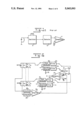
- FIGS. 1a and 1b show embodiments of a known inductive proximity sensor
- FIG. 1c shows an electronic circuit associated thereto
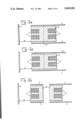
- FIG. 2 shows the principle of the inductive proximity sensor according to the invention
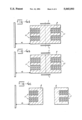
- FIGS. 3a, 3b and 3c show embodiments of the "fully shielded" mountable type of the sensor according to the invention
- FIGS. 4a, 4b and 4c show embodiments of the "unshielded" mountable type of the sensor according to the invention
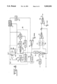
- FIG. 5 shows a basic circuit diagram of the sensor with electronic circuit according to the invention
- FIG. 6 shows the circuit diagram of the electronic circuit with the coils driven by an external oscillator
- FIG. 7 shows the circuit diagram of the electronic circuit with the coils driven by an internal oscillator
- FIG. 8 shows the circuit diagram of the electronic circuit with the coils driven by an external oscillator, and with synchronous amplitude detector.
- L1 indicates the measuring coil
- 8 indicates the block of magnetic material
- 3 indicates the approaching metal object to be detected, for example a metal plate.
- the sensor in FIG. 1a is of the so-called "unshielded” type which has to be mounted in a manner such that there is no metal present in the direct vicinity of said sensor apart from the approaching metal object.
- FIG. 1b shows the known sensor of the so-called “fully shielded” type which can be mounted in a metal holder, for example a robot arm and the like.
- Said sensor has a screening ring 4, for example of copper, around the block of magnetic material to screen the magnetic field.
- a metal platelet may possibly also be disposed at the rear of the block of magnetic material.
- the electronic circuit shown in FIG. 1c of the known sensor comprises an oscillator 5, for example a negative-impedance oscillator, a detector 6 and a comparator 7.
- the value of the negative impedance is determined by the external resistor shown at the oscillator.
- Connected to said oscillator is a LC circuit formed by the sensor measuring coil. If the equivalent (loss) parallel resistance of the LC circuit exceeds a particular value as a result of the approach of a metal object, the oscillator stops. This stopping of the oscillator is used to give a useful signal.
- This relatively simple principle is adequate only as long as no high accuracies are required.
- the inaccuracies in the detection distance as a result of the drift in the resistance of the coil wire and in the magnetic material due to change in temperature are, moreover, a large problem.
- the temperature coefficient, for example of the losses in the magnetic material has a spread which is just as large as the temperature coefficient itself.
- FIG. 2 shows the general principle of the sensor according to the invention.
- L2 indicates a reference coil
- 9 indicates a metal reference plate
- 10 indicates the transverse plane of symmetry of the sensor.
- the magnetic material is shown as composed of one piece.
- the specific properties of the measuring and reference coils L1, L2 are measured independently of each other by separate parts of the electronic circuit.
- the measuring coil is driven with a signal having frequency f1 and the reference coil with a signal having frequency f2, as a result of which these coils each generate a magnetic B field in the magnetic material.
- the screening ring 4 shown ensures that the H field generated by the measuring coil is virtually not enclosed by the reference coil and conversely. This construction achieves an effective screening between the two coils even though they are close to each other.
- the difference is measured between the specific property of the measuring coil L1 and the corresponding property of the reference coil L2.
- the sensor is of mirror-symmetrical construction and the coils L1 and L2 are identical, and the magnetic material is homogeneous, if both coils are driven with identical signals (same frequency and same amplitude), the equivalent loss resistance and the self-inductance of the measuring coil will be equal to that of the reference coil if the test plate 3 is at a distance d1 which is equal to the distance d2 of the reference measurement plate 9.
- d1 which is equal to the distance d2 of the reference measurement plate 9.
- the properties of said material are determined with the aid of the reference coil via a so-called direct or indirect measurement. If the measuring coil and the reference coil are as identical as possible, the properties of the measuring coil are determined via a so-called indirect measurement.
- the sensors of the so-called “fully shielded” mountable type shown in FIGS. 3a to 3c are each provided with a screening ring 4.
- Said screening ring projects a small amount on the reference coil side and thereby assumes the function of the reference plate 9.
- the equivalent loss resistance and the self-inductance of the reference coil L2 is not, or is virtually not, dependent on the presence of metal objects which may be situated behind the projecting screening ring.
- the end of the projecting screening ring may in turn also be closed off with a metal or copper plate.
- the block 8 is composed of magnetic material made from one piece of homogeneous material, as a result of which the properties of said material are again measured directly by means of the coil.
- the block 8 is composed of two pieces of essentially identical homogeneous magnetic material, as a result of which the properties of the magnetic material which is situated around the measuring coil L1 are indirectly measured by determining the properties of the magnetic material which is situated around the reference coil L2.
- the block 8 is composed of magnetic material again made from two pieces of essentially identical homogeneous material which are spaced from each other on either side of the plane of symmetry.
- the properties of the magnetic material around the measuring coil are again determined by an indirect measurement. Drift in the resistance and the self-inductance of both coils and the associated coil material due to temperature variation affects the detection distance. Because the risk of a larger temperature difference between the two coils and cores of magnetic materials exists in this embodiment, this embodiment is somewhat more inaccurate than that of FIGS. 3a and 3b.
- the sensors shown in FIGS. 4a to 4c of the so-called "unshielded" mountable type have a screening ring which only extend over a small distance around the circumference of the block of magnetic material.
- the object of this ring is again to sufficiently suppress the cross-talk of the H fields generated by the two coils.
- the differential sensitivity of the sensor is somewhat greater than that of the "fully shielded" mountable type, as a result of which a greater detection distance is achieved.
- a screening plate can be positioned between both pieces of magnetic material for the screening function instead of or in combination with the screening ring.
- a metal reference plate may be present at the rear of the sensor.
- the sensor is then no longer sensitive to metal objects which are situated behind said reference plate so that, for example, the electronic circuit may be accommodated in that position.
- the corresponding specific quantities of the two coils have to be measured at a particular frequency. If no coupling at all is present between the two coils, as, for example in the case of FIGS. 3c and 4c, the measurement of the specific quantity can be carried out by driving with two identical signals, i.e. identical frequency and amplitude.
- a capacitor is disposed parallel to the measuring coil and also parallel to the reference coil, as shown in FIG. 5.
- the circuit containing the measuring coil L1 has a resonance frequency f1 and the circuit containing the reference coil L2 has a resonance frequency f2.
- the measuring circuit is driven with a signal iin1 having frequency fos1 and the reference circuit is driven with a signal iin2 having frequency fos2.
- the amplitude across the measuring circuit is a measure of the ratio between the self-inductance L1 and the equivalent loss resistance R1 of the measuring coil, and the same applies to the ratio L2/R2 of the reference coil L2.
- the resonance frequencies f1 and f2 are a measure for the self-inductance of measuring coil and reference coil.
- the amplitude or envelope of the circuit voltage a or b can be detected with the aid of a peak detector 20, 21 or a synchronous detector 22, 23.
- the low-pass filter 24 incorporated after the detector determines the bandwidth of the detection and said filter suppresses any interference signals which are present at the output of the detector and are outside the passband.
- the frequencies fos1 and fos2 of both signals, which drive the two tuned circuits, are determined with the aid of the frequency-voltage converters 28, 29.
- the difference in the output direct voltage of both converters is a measure for the difference in the values of the self-inductances of both coils.
- This difference signal is available after the differential amplifier 30 (voltage from A).
- the difference in direct voltage after the low-pass filters 24 is available after the differential amplifier 61 (voltage from B) and is a measure for the difference in the ratio L/R of both coils.
- the voltages at A and at B are added to each other in a certain ratio with the aid of adder 62.
- the output voltage of this adder is then compared with an adjustable voltage Vref in the comparator 25 which provides an output voltage at D.
- the detection distance can be set by means of this adjustable value.
- Connected to each of the synchronous detectors 22, 23 is a local oscillator 26, 27 associated with the synchronous detection.
- the amplitude of the desired signal is transformed into a direct voltage Ug and the amplitude of the interference signal is also converted into a direct voltage Us1 so that the sum of the two direct voltages Ug+Us1 is produced at the output.
- an interference signal having a frequency fos1-fos2
- the interference direct voltage Us1 due to parasitic coupling always appears regardless of whether the frequencies fos1 and fos2 are or are not equal to each other.
- the detected interference signal Us1 due to parasitic coupling is reduced only by the filtering action of the resonance measuring circuit itself. If fos1 is approximately equal to f1 and fos2 is approximately equal to f2, the frequency difference between the two oscillator signals must be greater than half the bandwidth of the resonance measuring circuit to make use of this filtering action.
- the amplitude of the desired signal having frequency fos1 is converted into a direct voltage Ug which is a measure of the amplitude of said desired signal.
- the interference signal Us2 having frequency fos2 is converted into an interference signal Us having frequency (fos1-fos2).
- This signal can be suppressed by the filter after the detector.
- the frequency difference between the two drive signals must be greater than the bandwidth of said filter, that is to say, the detection bandwidth.
- Said interference signal is also, of course, filtered by the resonance measuring circuit just as in the case of the peak detector. In order to make use of this filtering action again, the frequency difference between the two oscillators must be greater than half the bandwidth of the resonance measuring circuit.
- both detectors deliver an interference direct voltage Us due to parasitic coupling in addition to the direct voltage Ug.
- the peak detector following the measuring circuit now measures a voltage Uga+Usa and the detector connected to the reference circuit measures a voltage Ugb+Usb.
- the detection distance of a sensor without the frequency-voltage converters 28, 29 and the amplifier 30 can then be adjusted independently of the temperature if the following is valid:
- K1 and K2 are constants. K1 must also be less than one and this is satisfied for a small coupling factor between the circuits.
- a small change in the resonance frequency due to a small variation in the parallel capacitance of the circuit has a negligible effect on the self-inductance and on the equivalent series resistance of the coil. It is assumed that both coils and their losses are precisely equal to each other. By making the capacitance over the two coils differ slightly from each other, a small difference is introduced in the resonance frequencies of the two circuits. As a result of this, the ratio, viz "gain", between the resistance Rs and the parallel resistance Rp for both resonance circuits is different. This can be compensated for in a simple manner by means of a difference in gain in the two detectors. This achieves the result that equal changes in L and Rs of the two sensor coils as a result of temperature changes have no effect on the detection distance.
- the above is applicable to unshielded mountable sensors.
- the projecting ring will result in a detuning of the reference circuit.
- Said detuning can, if necessary, be supplemented by providing a capacitor across the circuit in order to achieve the desired frequency offset.
- the drive signals can be generated both with external oscillators, in which case the sensor coils do not form part of the oscillator circuits, and with internal oscillators, in which case the sensor coils do form part of the oscillator circuits.
- FIG. 6 shows an embodiment for the external oscillators' case.
- the oscillator signal iinl to be used to drive the coil L1 must have a frequency equal to the resonance frequency of the circuit.
- an oscillator control loop 38 or a separate oscillator comprising the coil L1 in its circuit may be used.
- FIG. 6 shows an example of such an oscillator control loop in which a phase-locked loop 38 comprising an oscillator 32, a 90° phase shifter 36, a mixer 35, a loop filter 33, and an amplifier 34, which loop ensures that the voltage across the resonance circuit and the current to the resonance circuit are in phase.
- the oscillator signal from the oscillator 32 may also be used as a local oscillator signal for the synchronous detector 31. The same construction is applicable for driving the resonance circuit containing the reference coil L2.
- the drive signal for the reference coil L2 will have a crosstalk effect on the measuring coil L1 and an interference signal having frequency fos2 will be produced as a current source parallel to the resonance circuit containing coil L1. If the interference current falls within the passband of the circuit, no damping of the interference signal occurs. The interference voltage across the circuit then leads to an interference signal having frequency (fos1-fos2) in the control loop. The effect of said interference signal on the oscillator signal is determined by the filtering action of the control loop. If the interference component falls outside the passband of the control circuit, the effect thereof is reduced.
- fos1 is approximately equal to f1 and fos2 is approximately equal to f2
- the interference signal in the oscillator control loop has the result that the oscillator frequency fos1 is no longer equal to the resonance frequency f1 and, to some extent, moves in the direction of fos2.
- the oscillator control loop must therefore have a sufficiently large loop bandwidth, preferably greater than the detection bandwidth, in order to accommodate this.
- the drive signal of the oscillator 32 from the amplifier 34 is a measure for the detuning of the resonance circuit having the measuring coil L1 and therefore is a measure for the self-inductance of this coil.
- the self-inductance of the coil L1 in this way, is measured in a frequency-selective manner through which the oscillator control loop fulfils the function of a synchronous detector. Therefore a frequency-voltage converter is realized in this manner.
- FIG. 7 shows an embodiment for the case involving driving with an internal oscillator.
- the resonance circuit is incorporated directly in the oscillator circuit, as a result of which a control loop is no longer necessary, as is the case with external oscillator drive.
- the parasitic coupling between the two sensor coils again causes crosstalk and all the parasitic effects as explained in the case of driving with external oscillators also occur here.
- the filtering in the oscillator control loop is absent, as a result of which the effect of the crosstalk is greater in this case.
- injection locking may occur, as a result of which the frequencies of both oscillators become equal to each other.
- the senor becomes unusable since the constant K1 in the equation (1) has become almost one. It has also become impossible to measure the difference in the values of the self-inductances of the coils L1 and L2. That is to say, as a result of the approach of a metal object on the measuring coil side, the output voltages of the two detectors change to an equal extent. The difference voltage between the two detectors does not undergo any change, as a result of which detection of the metal object is impossible.
- the ratio L/R was measured by measuring the amplitude of the circuit voltage at resonance, the amplitude of the drive signal iin of the circuit being kept constant (see FIG. 6). It is also possible to adjust the current iin with a control loop in a manner such that the amplitude of the circuit voltage remains constant at resonance when the value of the equivalent loss resistance varies. The quantity which adjusts the amplitude of iin is then a measure of the ratio L/R.
- FIG. 7 A possible embodiment for this purpose is shown in FIG. 7.
- the so-called internal oscillator 42 in which the resonance circuit forms part of the oscillator circuit, is used to generate the drive signal for the coil and comprises amplifier 44 and mixer 45.
- the amplitude of said drive signal is adjusted by the adjustable current source 50.
- This current source is adjusted by a loop which comprises synchronous detector 41, loop filter 43, amplifier 46 having an adjustable voltage source at the input, and adjustable current source 50, in a manner such that the voltage from the detector is kept constant at the voltage Vamp, which determines the amplitude across the circuit.
- the drive voltage which adjusts the current source 50 is then a measure of the ratio L/R.
- a similar circuit in which the reference coil L2 is incorporated is of course present.
- the drive voltages of the two circuits are fed to the difference amplifier 49 via the filter 47 and 48 respectively, and are again compared with the adjustable voltage source Vref in order to adjust the detection distance.
- FIG. 8 A possible embodiment, in which also the self-inductances of the coils are measured with the aid of a frequency-selective measurement, is indicated in FIG. 8.
- the so-called external oscillator 38 whereby the resonance circuit does not form part of the oscillator circuit, is used for generating the drive signal for the coil and comprises a phase-locked loop such as indicated in FIG. 6, a mixer 45 being added.
- the amplitude across the circuit is determined with the aid of synchronous detector 41, loop filter 43, and amplifier 46 such as indicated in FIG. 7.
- a similar circuit is provided in which the reference coil L2 is accomodated.
- the drive voltages for the current sources 50 of both circuits are supplied via the filters 47 and 48 respectively to the differential amplifier 51.
- the output signal of this amplifier then is a measure for the difference in the ratio L/R of both coils.
- the drive signals of both oscillators 32 are applied via the filters 54, 55 to the differential amplifier 53.
- the output signal of this amplifier is a measure for the difference in the values of the self-inductances of both coils. Both output signals can be added in any ratio to each other in the adder 52. The signal then is applied to the comparator 49. The adjustment of the detection distance then is possible with the aid of the adjustable voltage source Vref.
Landscapes
- Life Sciences & Earth Sciences (AREA)
- Engineering & Computer Science (AREA)
- Physics & Mathematics (AREA)
- Remote Sensing (AREA)
- Geology (AREA)
- Environmental & Geological Engineering (AREA)
- Electromagnetism (AREA)
- General Life Sciences & Earth Sciences (AREA)
- General Physics & Mathematics (AREA)
- Geophysics (AREA)
- Measurement Of Length, Angles, Or The Like Using Electric Or Magnetic Means (AREA)
- Measurement Of Resistance Or Impedance (AREA)
- Investigating Or Analyzing Materials By The Use Of Magnetic Means (AREA)
- Geophysics And Detection Of Objects (AREA)
Applications Claiming Priority (2)
| Application Number | Priority Date | Filing Date | Title |
|---|---|---|---|
| NL8701980A NL8701980A (nl) | 1987-08-24 | 1987-08-24 | Inductieve naderingssensor. |
| NL8701980 | 1987-08-24 |
Publications (1)
| Publication Number | Publication Date |
|---|---|
| US5065093A true US5065093A (en) | 1991-11-12 |
Family
ID=19850490
Family Applications (1)
| Application Number | Title | Priority Date | Filing Date |
|---|---|---|---|
| US07/235,103 Expired - Fee Related US5065093A (en) | 1987-08-24 | 1988-08-23 | Inductive proximity sensor for detecting an object starting electrical conductivity |
Country Status (4)
| Country | Link |
|---|---|
| US (1) | US5065093A (fr) |
| EP (1) | EP0305013A3 (fr) |
| JP (1) | JPH01145501A (fr) |
| NL (1) | NL8701980A (fr) |
Cited By (20)
| Publication number | Priority date | Publication date | Assignee | Title |
|---|---|---|---|---|
| US5373123A (en) * | 1992-12-21 | 1994-12-13 | Otis Elevator Company | Electromagnetic gaging of elevator rails and other structures |
| FR2738641A1 (fr) * | 1995-09-11 | 1997-03-14 | Silec Liaisons Elec | Capteur electromagnetique cylindrique et procede de determination simultanee de differents parametres d'une cible cylindrique associee |
| US5793176A (en) * | 1993-04-02 | 1998-08-11 | Sandia Corporation | Spatial feature tracking impedence sensor using multiple electric fields |
| US5952822A (en) * | 1996-10-24 | 1999-09-14 | Allen-Bradley Company, Llc | Method and apparatus for proximity sensing in the presence of an external field |
| US20030071638A1 (en) * | 2001-09-07 | 2003-04-17 | Sick Ag | Inductive proximity sensor |
| US6570377B1 (en) * | 2000-10-02 | 2003-05-27 | Honeywell International Inc. | Systems and method for determining proximity sensor characteristics |
| US20030179000A1 (en) * | 2000-03-14 | 2003-09-25 | Gregg John Francis | Position and electromagnetic field sensor |
| US6661635B1 (en) * | 1999-07-26 | 2003-12-09 | Moeller Gmbh | Electronic drive control apparatus |
| US6803757B2 (en) | 2001-10-02 | 2004-10-12 | Bentley Nevada, Llc | Multi-coil eddy current proximity probe system |
| US20040223283A1 (en) * | 2003-05-05 | 2004-11-11 | Nikon Corporation | Adaptive gain adjustment for electromagnetic devices |
| US20060103372A1 (en) * | 2004-11-18 | 2006-05-18 | Simmonds Precision Products, Inc. | Method of non-intrusive inductive proximity sensing through a conductive barrier |
| US20060161356A1 (en) * | 2002-07-24 | 2006-07-20 | Michel Desroses | Device for detecting the nature of a blow and measuring its force, method for using same and use thereof for refereeing a sport |
| US20080012560A1 (en) * | 2006-07-11 | 2008-01-17 | Crowley Christopher W | Passenger screening system and method |
| US20080206104A1 (en) * | 2005-06-17 | 2008-08-28 | Koninklijke Philips Electronics, N.V. | Accurate Magnetic Biosensor |
| US20080309329A1 (en) * | 2003-07-30 | 2008-12-18 | Koninklike Philips Electronics N.V. | On-Chip Magnetic Sensor Device with Suppressed Cross-Talk |
| US20090189600A1 (en) * | 2008-01-26 | 2009-07-30 | Pepperl+Fuchs, Inc. | Metal face inductive proximity sensor |
| EP2565683A1 (fr) * | 2011-09-02 | 2013-03-06 | Schneider Electric Industries SAS | Ensemble multicouche à double bobinage blindé pour détecteur inductif |
| WO2014129703A1 (fr) * | 2013-02-21 | 2014-08-28 | Truwin Co.,Ltd. | Capteur de proximité par induction |
| US20160086482A1 (en) * | 2014-09-18 | 2016-03-24 | Texas Instruments Incorporated | Inductive security sensor not susceptible to magnetic tampering |
| US20160202297A1 (en) * | 2015-01-14 | 2016-07-14 | Insitu, Inc. | Systems and methods for signal quantization |
Families Citing this family (9)
| Publication number | Priority date | Publication date | Assignee | Title |
|---|---|---|---|---|
| JP2739742B2 (ja) * | 1989-12-20 | 1998-04-15 | オムロン株式会社 | 差動コイル型近接スイッチ |
| DE4200518A1 (de) * | 1992-01-11 | 1993-07-15 | Bosch Gmbh Robert | Metallsuchdetektor |
| FR2715477B1 (fr) * | 1994-01-21 | 1996-04-12 | Crouzet Automatismes | Détecteur de proximité inductif redondant. |
| GB9901101D0 (en) * | 1999-01-19 | 1999-03-10 | British Nuclear Fuels Plc | Proximity sensor |
| CA2362408A1 (fr) * | 1999-02-22 | 2000-08-31 | Allen Ray Herron | Dispositif de detection et d'imagerie utilisant le biomagnetisme |
| US7719263B2 (en) * | 2006-11-22 | 2010-05-18 | Zf Friedrichshafen Ag | Inductive position measuring device or goniometer |
| GB2472275A (en) * | 2009-07-31 | 2011-02-02 | Oxford Rf Sensors Ltd | Proximity sensor |
| DE102015222017A1 (de) * | 2015-09-15 | 2017-03-16 | Micro-Epsilon Messtechnik Gmbh & Co. Kg | Vorrichtung und Sensor zur kontaktlosen Abstands- und/oder Positionsbestimmung eines Messobjektes |
| JP6961862B2 (ja) * | 2016-08-25 | 2021-11-05 | ケイセイ医科工業株式会社 | 体内磁性体検出装置 |
Citations (12)
| Publication number | Priority date | Publication date | Assignee | Title |
|---|---|---|---|---|
| DE322852C (de) | 1919-09-27 | 1920-07-10 | Franklin Ind Ges M B H | Einrichtung zur Erzeugung von periodisch unterbrochenem Gleichstrom durch abwechselnde Verdampfung und Wiederverdichtung einer leitenden Fluessigkeit |
| US3510858A (en) * | 1967-09-08 | 1970-05-05 | Foxboro Co | Force-balance instrument with electrical detector arrangement |
| US3659194A (en) * | 1970-11-25 | 1972-04-25 | Alfred A Blackerby | Magnetic sensor having a heat treated housing for collimating the sensor{40 s flux |
| US3707671A (en) * | 1970-05-01 | 1972-12-26 | Robert S Morrow | Inductive vibration pickup apparatus |
| FR2346679A1 (fr) * | 1976-04-02 | 1977-10-28 | Itt Produits Ind | Detecteur de proximite electromagnetique |
| US4095181A (en) * | 1976-12-17 | 1978-06-13 | The Boeing Company | Rotating pot shaped eddy current probe in which only a small fraction of the lip forming the outer core portion is retained |
| SU681365A1 (ru) * | 1978-03-07 | 1979-08-25 | Московское Ордена Ленина И Ордена Трудового Красного Знамени Высшее Техническое Училище Им.Н.Э.Баумана | Индуктивно-вихретоковый датчик с температурной самокомпенсацией |
| US4419646A (en) * | 1979-12-22 | 1983-12-06 | Eduard Hermle | Electric proximity sensor |
| DE3228524A1 (de) * | 1982-07-30 | 1984-02-09 | Siemens AG, 1000 Berlin und 8000 München | Induktiver annaeherungsschalter |
| FR2545221A1 (fr) * | 1983-04-29 | 1984-11-02 | Thomson Jeumont Cables | Capteur de donnees, par courant de foucault, et ensemble de controle de resistivite muni d'un tel capteur |
| US4593244A (en) * | 1982-08-06 | 1986-06-03 | Australian Wire Industries Pty. Ltd. | Determination of the thickness of a coating on a highly elongated article |
| JPS6287349A (ja) * | 1985-10-14 | 1987-04-21 | 大日本印刷株式会社 | 化粧材 |
Family Cites Families (2)
| Publication number | Priority date | Publication date | Assignee | Title |
|---|---|---|---|---|
| US3209292A (en) * | 1961-12-18 | 1965-09-28 | Square D Co | Device for detecting the proximity of metal objects |
| CH667954A5 (de) * | 1985-01-11 | 1988-11-15 | Baumer Electric Ag | Naeherungsschalter mit beruehrungsloser ausloesung. |
-
1987
- 1987-08-24 NL NL8701980A patent/NL8701980A/nl not_active Application Discontinuation
-
1988
- 1988-08-23 US US07/235,103 patent/US5065093A/en not_active Expired - Fee Related
- 1988-08-24 EP EP88201808A patent/EP0305013A3/fr not_active Withdrawn
- 1988-08-24 JP JP63208461A patent/JPH01145501A/ja active Pending
Patent Citations (12)
| Publication number | Priority date | Publication date | Assignee | Title |
|---|---|---|---|---|
| DE322852C (de) | 1919-09-27 | 1920-07-10 | Franklin Ind Ges M B H | Einrichtung zur Erzeugung von periodisch unterbrochenem Gleichstrom durch abwechselnde Verdampfung und Wiederverdichtung einer leitenden Fluessigkeit |
| US3510858A (en) * | 1967-09-08 | 1970-05-05 | Foxboro Co | Force-balance instrument with electrical detector arrangement |
| US3707671A (en) * | 1970-05-01 | 1972-12-26 | Robert S Morrow | Inductive vibration pickup apparatus |
| US3659194A (en) * | 1970-11-25 | 1972-04-25 | Alfred A Blackerby | Magnetic sensor having a heat treated housing for collimating the sensor{40 s flux |
| FR2346679A1 (fr) * | 1976-04-02 | 1977-10-28 | Itt Produits Ind | Detecteur de proximite electromagnetique |
| US4095181A (en) * | 1976-12-17 | 1978-06-13 | The Boeing Company | Rotating pot shaped eddy current probe in which only a small fraction of the lip forming the outer core portion is retained |
| SU681365A1 (ru) * | 1978-03-07 | 1979-08-25 | Московское Ордена Ленина И Ордена Трудового Красного Знамени Высшее Техническое Училище Им.Н.Э.Баумана | Индуктивно-вихретоковый датчик с температурной самокомпенсацией |
| US4419646A (en) * | 1979-12-22 | 1983-12-06 | Eduard Hermle | Electric proximity sensor |
| DE3228524A1 (de) * | 1982-07-30 | 1984-02-09 | Siemens AG, 1000 Berlin und 8000 München | Induktiver annaeherungsschalter |
| US4593244A (en) * | 1982-08-06 | 1986-06-03 | Australian Wire Industries Pty. Ltd. | Determination of the thickness of a coating on a highly elongated article |
| FR2545221A1 (fr) * | 1983-04-29 | 1984-11-02 | Thomson Jeumont Cables | Capteur de donnees, par courant de foucault, et ensemble de controle de resistivite muni d'un tel capteur |
| JPS6287349A (ja) * | 1985-10-14 | 1987-04-21 | 大日本印刷株式会社 | 化粧材 |
Non-Patent Citations (1)
| Title |
|---|
| Patent Abstracts of Japan (Vol. 9, No. 199) * |
Cited By (33)
| Publication number | Priority date | Publication date | Assignee | Title |
|---|---|---|---|---|
| US5373123A (en) * | 1992-12-21 | 1994-12-13 | Otis Elevator Company | Electromagnetic gaging of elevator rails and other structures |
| US5793176A (en) * | 1993-04-02 | 1998-08-11 | Sandia Corporation | Spatial feature tracking impedence sensor using multiple electric fields |
| FR2738641A1 (fr) * | 1995-09-11 | 1997-03-14 | Silec Liaisons Elec | Capteur electromagnetique cylindrique et procede de determination simultanee de differents parametres d'une cible cylindrique associee |
| WO1997010516A1 (fr) * | 1995-09-11 | 1997-03-20 | Sagem S.A. | Capteur electromagnetique cylindrique et procede de determination simultanee de differents parametres d'une cible cylindrique associee |
| US5952822A (en) * | 1996-10-24 | 1999-09-14 | Allen-Bradley Company, Llc | Method and apparatus for proximity sensing in the presence of an external field |
| US6661635B1 (en) * | 1999-07-26 | 2003-12-09 | Moeller Gmbh | Electronic drive control apparatus |
| US6984994B2 (en) * | 2000-03-14 | 2006-01-10 | Isis Innovation Limited | Position and electromagnetic field sensor |
| US20060097732A1 (en) * | 2000-03-14 | 2006-05-11 | Isis Innovation Limited | Position and electromagnetic field sensor |
| US20030179000A1 (en) * | 2000-03-14 | 2003-09-25 | Gregg John Francis | Position and electromagnetic field sensor |
| US6570377B1 (en) * | 2000-10-02 | 2003-05-27 | Honeywell International Inc. | Systems and method for determining proximity sensor characteristics |
| US6822440B2 (en) * | 2001-09-07 | 2004-11-23 | Sick Ag | Inductive proximity sensor |
| US20030071638A1 (en) * | 2001-09-07 | 2003-04-17 | Sick Ag | Inductive proximity sensor |
| US6803757B2 (en) | 2001-10-02 | 2004-10-12 | Bentley Nevada, Llc | Multi-coil eddy current proximity probe system |
| US20060161356A1 (en) * | 2002-07-24 | 2006-07-20 | Michel Desroses | Device for detecting the nature of a blow and measuring its force, method for using same and use thereof for refereeing a sport |
| US7046496B2 (en) * | 2003-05-05 | 2006-05-16 | Nikon Corporation | Adaptive gain adjustment for electromagnetic devices |
| US20040223283A1 (en) * | 2003-05-05 | 2004-11-11 | Nikon Corporation | Adaptive gain adjustment for electromagnetic devices |
| US20080309329A1 (en) * | 2003-07-30 | 2008-12-18 | Koninklike Philips Electronics N.V. | On-Chip Magnetic Sensor Device with Suppressed Cross-Talk |
| US20060103372A1 (en) * | 2004-11-18 | 2006-05-18 | Simmonds Precision Products, Inc. | Method of non-intrusive inductive proximity sensing through a conductive barrier |
| US7129701B2 (en) * | 2004-11-18 | 2006-10-31 | Simmonds Precision Products, Inc. | Method of inductive proximity sensing |
| US20080206104A1 (en) * | 2005-06-17 | 2008-08-28 | Koninklijke Philips Electronics, N.V. | Accurate Magnetic Biosensor |
| US20080012560A1 (en) * | 2006-07-11 | 2008-01-17 | Crowley Christopher W | Passenger screening system and method |
| US7397239B2 (en) | 2006-07-11 | 2008-07-08 | Ge Security, Inc. | Passenger screening system and method |
| US20090189600A1 (en) * | 2008-01-26 | 2009-07-30 | Pepperl+Fuchs, Inc. | Metal face inductive proximity sensor |
| US8154278B2 (en) | 2008-01-26 | 2012-04-10 | Pepperl+Fuchs, Inc. | Metal face inductive proximity sensor |
| EP2565683A1 (fr) * | 2011-09-02 | 2013-03-06 | Schneider Electric Industries SAS | Ensemble multicouche à double bobinage blindé pour détecteur inductif |
| FR2979712A1 (fr) * | 2011-09-02 | 2013-03-08 | Schneider Electric Ind Sas | Ensemble multicouche a double bobinage blinde pour detecteur inductif |
| CN102981183A (zh) * | 2011-09-02 | 2013-03-20 | 施耐德电器工业公司 | 感应式检测器的屏蔽双线圈多层组件 |
| US9182514B2 (en) | 2011-09-02 | 2015-11-10 | Schneider Electric Industries Sas | Shielded double-coil multilayer assembly for inductive detector |
| WO2014129703A1 (fr) * | 2013-02-21 | 2014-08-28 | Truwin Co.,Ltd. | Capteur de proximité par induction |
| US20160086482A1 (en) * | 2014-09-18 | 2016-03-24 | Texas Instruments Incorporated | Inductive security sensor not susceptible to magnetic tampering |
| US9953515B2 (en) * | 2014-09-18 | 2018-04-24 | Texas Instruments Incorporated | Inductive security sensor not susceptible to magnetic tampering |
| US20160202297A1 (en) * | 2015-01-14 | 2016-07-14 | Insitu, Inc. | Systems and methods for signal quantization |
| US9753068B2 (en) * | 2015-01-14 | 2017-09-05 | Insitu Inc. | Systems and methods for signal quantization |
Also Published As
| Publication number | Publication date |
|---|---|
| NL8701980A (nl) | 1989-03-16 |
| JPH01145501A (ja) | 1989-06-07 |
| EP0305013A3 (fr) | 1989-04-05 |
| EP0305013A2 (fr) | 1989-03-01 |
Similar Documents
| Publication | Publication Date | Title |
|---|---|---|
| US5065093A (en) | Inductive proximity sensor for detecting an object starting electrical conductivity | |
| US4509023A (en) | Oscillator with a temperature compensated oscillating coil | |
| US5012206A (en) | Inductive proximity switch | |
| US4206401A (en) | Length measuring system | |
| US4924172A (en) | Capacitive sensor and electronic circuit for non-contact distance measurement | |
| US8008909B2 (en) | Analysis and compensation circuit for an inductive displacement sensor | |
| US3292077A (en) | Conductivity measuring system | |
| US7132825B2 (en) | Detection device | |
| US6031430A (en) | Temperature stabilized oscillator and proximity switch containing the oscillator | |
| US4593241A (en) | Hall generator circuit with temperature compensation | |
| JPH04231936A (ja) | 核磁気共鳴撮像システム | |
| US5331277A (en) | Inductive divider position sensor with fixed and variable impedance inductors | |
| US2866336A (en) | Liquid level gage | |
| US5157288A (en) | Phase shifting circuits | |
| JPS5972205A (ja) | アナログ量検知用lc発振器の周波数可変方法 | |
| GB2054867A (en) | Eddy-current distance measuring apparatus | |
| EP0079955A4 (fr) | Circuit de mesure de l'impedance. | |
| US4030085A (en) | Nonferromagnetic linear variable differential transformer | |
| US4598260A (en) | Eddy current proximeter | |
| US3621385A (en) | Meter for measuring capacitances of extremely high loss dielectric materials | |
| US2923880A (en) | Apparatus for impedance measurements | |
| US4528498A (en) | Frequency compensating current circuit for a current comparator capacitance bridge | |
| US3175145A (en) | Motive means for electrically controlling distance between a body and object | |
| US3437920A (en) | Transducer circuits with frequency-amplitude control | |
| US3454874A (en) | Instrument for measuring the thickness of a non-conducting film on a metal base and for measuring the resistivity of a metal sample |
Legal Events
| Date | Code | Title | Description |
|---|---|---|---|
| AS | Assignment |
Owner name: CATENA PRODUCT DEVELOPMENT B.V., POORTWEG 2-4, 261 Free format text: ASSIGNMENT OF ASSIGNORS INTEREST.;ASSIGNORS:NAUTA, HENDRIKUS C.;NORDHOLT, ERNST H.;REEL/FRAME:004969/0119 Effective date: 19880919 Owner name: CATENA PRODUCT DEVELOPMENT B.V., NETHERLANDS Free format text: ASSIGNMENT OF ASSIGNORS INTEREST;ASSIGNORS:NAUTA, HENDRIKUS C.;NORDHOLT, ERNST H.;REEL/FRAME:004969/0119 Effective date: 19880919 |
|
| CC | Certificate of correction | ||
| REMI | Maintenance fee reminder mailed | ||
| LAPS | Lapse for failure to pay maintenance fees | ||
| FP | Lapsed due to failure to pay maintenance fee |
Effective date: 19961115 |
|
| STCH | Information on status: patent discontinuation |
Free format text: PATENT EXPIRED DUE TO NONPAYMENT OF MAINTENANCE FEES UNDER 37 CFR 1.362 |