US5070709A - Striping system for circular knitting machine - Google Patents
Striping system for circular knitting machine Download PDFInfo
- Publication number
- US5070709A US5070709A US07/614,024 US61402490A US5070709A US 5070709 A US5070709 A US 5070709A US 61402490 A US61402490 A US 61402490A US 5070709 A US5070709 A US 5070709A
- Authority
- US
- United States
- Prior art keywords
- yarnguide
- yarn
- rod
- lever
- slide
- Prior art date
- Legal status (The legal status is an assumption and is not a legal conclusion. Google has not performed a legal analysis and makes no representation as to the accuracy of the status listed.)
- Expired - Fee Related
Links
- 238000009940 knitting Methods 0.000 title claims description 7
- 230000007246 mechanism Effects 0.000 claims description 29
- 230000000994 depressogenic effect Effects 0.000 claims description 7
- 239000011435 rock Substances 0.000 claims description 5
- 230000000717 retained effect Effects 0.000 claims description 3
- 230000001105 regulatory effect Effects 0.000 claims description 2
- 230000005540 biological transmission Effects 0.000 description 1
- 230000015556 catabolic process Effects 0.000 description 1
- 239000004744 fabric Substances 0.000 description 1
Images



Classifications
-
- D—TEXTILES; PAPER
- D04—BRAIDING; LACE-MAKING; KNITTING; TRIMMINGS; NON-WOVEN FABRICS
- D04B—KNITTING
- D04B15/00—Details of, or auxiliary devices incorporated in, weft knitting machines, restricted to machines of this kind
- D04B15/38—Devices for supplying, feeding, or guiding threads to needles
- D04B15/54—Thread guides
- D04B15/58—Thread guides for circular knitting machines; Thread-changing devices
- D04B15/60—Thread guides for circular knitting machines; Thread-changing devices with thread-clamping or -severing devices
Definitions
- the invention relates to a striping system for a circular knitting machine, the machine comprising an axis of rotation, a needle cylinder provided with needles adapted to receive knitting yarn, cam sections for regulating the movement of said needles, a support for said cam sections, stripers and a common yarnguide from which the yarn may run to the needle.
- stripers are used allowing the pattern it is desired to knit to be programmed without taking the pattern that was being knitted into account. This leads to the frequent error of programming the coming into operation of a moving yarnguide rod which was already in operation.
- the conventional systems require the striper to be subjected to three selections: one for the yarnguide which has to come into operation; another for freeing the incoming yarn and a third one for cutting the outgoing yarn. All this creates a complex situation.
- each rod being provided with a yarn notch, each rod being capable of pivoting between a first position away from said axis of rotation and a second position towards said axis of rotation;
- a support member associated with each yarnguide rod and fixedly attached to a gripper member for retaining the yarn and with a shears member for cutting said yarn, said support member being provided with first means to be pushed downwardly and second means to be pushed upwardly, and being adapted to slide along the rod between a first lower position in which the gripper member retains the yarn and a second upper position in which the gripper member does not retain the yarn, said shears member being adapted to cut the yarn on moving from said second to said first position;
- each yarnguide rod provided with a lower contour in which there is provided a recess for guiding the yarn between the infeed yarnguide and the common yarnguide;
- a moving cam adapted to pick up the yarn retained in a yarnguide rod when the latter is in said second position thereof, such that the yarn slides along said lower contour to reach said recess, to be inserted in the common yarnguide and to be captured by the needle;
- a pivoting mechanism for pivoting each yarnguide rod comprising a last rocking lever having an end;
- said selection device comprises:
- a slide member for each pivoting mechanism which is adapted to slide between a retracted position and an extended position, which is housed in a slot and is provided with: a tail portion capable of being depressed into the slot against the urging of a second spring; a rear engagement surface; an upper engagement surface; a front engagement surface; an upper butt and a recess in which there is inserted said end of said last rocking lever with a clearance therebetween, such that a sliding movement of the slide member from said retracted position of a magnitude greater than said clearance, causes said last rocking lever to rock and the actuation of said pivoting mechanism;
- a single selection box which, for each slide member, comprises a selector adapted to occupy a retracted inoperative position or an extended operative position in which it engages said upper butt, causing the slide member to slide over a first distance of a magnitude of the order of said clearance;
- said closing mechanism is provided with a first rocking arm pivotably connected to a closing lever which, on the one hand, is adapted to slide between a first retracted position to which it is urged by a third spring and a second, extended position and, on the other hand it is also adapted to pivot between an inoperative position, to which it is urged by a fourth spring, and an operative position to which it is led by the pivoting of any yarnguide rod to the second position thereof towards said axis of rotation, said closing lever having a terminal edge which, when the closing lever has been pivoted to the operative position thereof and is slid towards the extended position thereof, engages said first means of said support member, leading it to a first lower position thereof.
- the invention also contemplates that said opening mechanism be provided with a second rocking arm pivotably attached to an opening lever which is adapted to slide between a low position to which it is urged by a fifth spring and a high position, said opening lever having an inner operative edge which, when the lever slides from said low position to said high position, is adapted to engage said second means of said support member, when the yarnguide rod corresponding to the support member is in the second position thereof towards the axis of rotation.
- FIG. 1 is an elevation view of the system of the invention, mounted on a circular knitting machine shown in part.
- FIG. 2 is a side elevation view, on a larger scale, of a yarnguide rod attached to a corresponding lever.
- FIG. 3 is a front view of the lower end of the yarnguide rod, the shears member being illustrated in part and the gripper member having been deleted for greater clarity.
- FIG. 4 is a partial elevation view of the striper, without a frame cover, showing a yarnguide rod pivoted to the first position thereof away from the axis of rotation; the remaining yarnguide rods have been omitted for clarity, although at least one of them is in a second position thereof towards the axis of rotation, in view of the position of the closing lever.
- FIG. 5 is a similar view to the previous one, with the yarnguide rod pivoted to the second position thereof towards the axis of rotation.
- FIG. 7 is a similar view to the previous one, showing a further position of the slide member.
- FIG. 8 is an elevation view of the top portion of the striper associated with the selection box and other system parts, the rigid front cover of the frame being shown partly cut away.
- FIG. 9 is a part elevation view of the striper, showing a yarnguide rod in the first pivoting position thereof and with the support member in the second upper position thereof and another yarnguide rod in the second pivoting position thereof and with the support member in the first lower position thereof; only one last rocking lever has been shown.
- FIG. 10 is a similar view to the previous one, with the lower and upper positions of the support members being reversed.
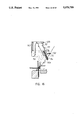
- FIG. 11 is an elevation view of the lower portion of the striper in an operative stage thereof; the guide plate has been drawn in phantom lines for clarity.
- FIG. 11(a) is a perspective view showing the parts of the striping mechanism 2 shown in FIG. 11, with the needle cylinder and common yarnguide removed for clarity.
- FIG. 12 is a cross section view on the line XII--XII of FIG. 11, limited to the moving cam.
- FIGS. 13 to 15 are similar views to FIG. 11, showing other operative stages of the striper.
- FIG. 16 is a plan view of the radial and axial cams operating on the striper.
- striper 2 is mounted on a circular knitting machine. A large part of the members forming the yarn changeover system are contained in the striper 2 and detailed reference will be made to said members hereinafter.
- the needle cylinder 4 is illustrated at the bottom of the Figure and is seen to be provided with grooves housing needles 6 and other items, a description of which is not necessary for an understanding of the invention.
- Sinkers 8 cooperate with said needles and the cam sections 10 and cams 12, for the needles.
- the cam sections 14 and cams 16 for the sinkers 8 are also shown.
- the cam sections 14 are supported on a support 18, mounted in turn on brackets 20.
- the cam sections 10 are held by a support 22, serving as a base for columns 24 which in turn support the said brackets 20.
- the columns 24 support a ring 26 to which the stripers 2 are attached by bolts 28, taking advantage of an appropriate configuration of the ring 26 and the stripers.
- a rotating ring 30 driven by the kinematic chain (not illustrated) of the machine for rotation around an axis of rotation (not shown either and which would be situated to the left of FIG. 1), at the same speed as the needle cylinder 4.
- a selection box 32 (FIG. 8), to be referred to hereinafter, is mounted on the ring 30.
- the ring 30 also supports a first radial cam 34 and a second radial cam 36, as well as three axial cams 38, 40 and 42.
- the second radial cam 36 is supported by an intermediate support ring 37.
- radial is used to designate the cams whose operative surface is arcuate and is held generally parallel to the machine axis of rotation.
- axial cams are those whose operative surface is the lower surface of the cam and which, therefore, is oriented generally normal to said axis of rotation, although such surface may be curved.
- the ring 30 draws along a support arm 44 for holding a support 46 on which a moving cam 48 is mounted in association with the needle removal area of the striping machines.
- the purpose of the moving cam is to take the yarn offered by the stripers to be changed and place it within a common yarnguide 52 to be captured by the needles 6.
- Each striper 2 is provided preferably with two parallel rigid covers 54 (of which only the front one is seen in FIG. 1). A plurality of shafts for the elements of the different mechanisms are located between the covers. Attached to the striper are guide plates 56 having a lower contour 58 wherein there is located a recess 60 for guiding the yarn extending between the needle and the infeed yarnguides 62.
- Yarnguide rods 64 are very important for the system.
- Each yarnguide rod 64 (FIGS. 2 and 3) is provided with a generally hook shaped notch 66 and the rods are pivotable between a first position 64a away from the axis of rotation of the machine and a position 64b towards said axis (FIG. 1), there being a first spring 68 (FIGS. 4 and 5) urging the corresponding rod 64 to said first position.
- Each rod 64 is located between two guide plates 56.
- Each yarnguide rod 64 is associated with a support member 70 which, in turn is attached to a gripper member 72 for retaining the yarn and a shears member 74 for cutting the yarn.
- the attachment may be effected, for example, by tabs 76 on each of said members extending through a window 78 of the support member 70.
- the support member 70 together with the members 72 and 74, is adapted to slide along the rod (to which it is snugly mounted) between a first lower position (70a in FIG. 4) and a second upper position (70b in FIG. 5). In said first position the gripper member 72 retains the yarn against the rod body 64 and in the second upper position the yarn is freed from the gripper member.
- the notch 66 is provided with an edge 80 which, together with the lower edge 82 of the shears member cut the yarn when the support member 70, together with the shears member 74 moves from said second position to said first position.
- Each support member 70 is provided with first means for being pushed downwards towards said first position and second means for being pushed upwardly towards said second position.
- these first and second means may be formed by respective fins 84 and 86 respectively having an upper transverse surface 88 and a lower transverse surface 90.
- Each yarnguide rod 64 is attached to a lever 92 pivotably connected to another lever 94 and the latter in turn is attached to a last rocking lever 96 which has an end 98.
- each slide member 100 is connected to a pivoting mechanism for the yarnguide rods 64, it should be said here that the slide member is provided with a recess 106 in which said end 98 is inserted with a clearance therebetween.
- any sliding movement of the slide member of a magnitude inferior to that of the clearance does not cause the slide member 100 to engage said end 98 and, therefore, the last lever 96 does not rock.
- the last lever 96 When said sliding movement is greater than said clearance, the last lever 96 is caused to rock, thereby moving the lever 94 and, therewith, the lever 92.
- the last named is connected to the corresponding yarnguide rod 64, whereby a sliding movement of the slide member 100 from the retracted position thereof to the extended position thereof causes the yarnguide rod 64 to pivot from the first position 70a to the second position 70b thereof.
- an opposite sliding movement of the slide member 100 causes the rod 64 to pivot in the opposite direction, i.e. from the second position 70b to the first position 70a thereof.
- FIGS. 4 and 5 For greater clarity, reference has been made in FIGS. 4 and 5 only to the items involved in the rod pivoting mechanism.
- the slide member 100 is seen (FIGS. 6, 7 and 8) to have furthermore a tail portion 108 capable of being depressed to the bottom 104 of the slot 102, against the force of the second spring 107.
- a rear engagement surface 110 there is a rear engagement surface 110, an upper engagement surface 112 and a front engagement surface 114.
- each slide member 100 is provided with an upper butt 116; the position of the upper butt 116 of a slide member 100 is advanced or in arrears relative to the upper butts of the possibly contiguous slide members, so that each upper butt 116 associates itself with each of the selectors 118 of the selected box 32, such that the respective butts 116 of the different slide members are mutually offset.
- a single selection box 32 provided with as many selectors 118 as there are butts 116, i.e. as slide members 100 and the selectors are correspondingly offset with the butts 116.
- Said selectors 118 may be in an inoperative retracted position or an operative extended position. They are provided with a sloping surface 120 which engages the corresponding butt 116, when the selector is in the operative position and, with little effort, the butt 116 may be caused to advance over a first distance (portion between initial position 110 and retracted position 110a in FIG. 6), equivalent to the clearance between the end 98 and recess 106.
- the continued forward movement of the selector 118 places the butt 116 in front of the head 122 of the selector, whereby it is led to its inoperative position, in which it remains or not, depending on whether programmable magnetic elements are excited or not.
- the corresponding selector 118 moves to the operative position thereof and engages the upper butt 116 of the slide member 100.
- the slide member 100 moves away from the initial position thereof and slides over the said first distance and thus the upper engagement surface 112 is taken out of the reach of the first axial cam 38. Consequently, the tail portion 108 is not depressed in the slot, whereby the rear surface (in position 110a) is engaged by the first radial cam 34 and the slide member is pushed towards its extended position, whereby the recess 106 thereof engages the end 98 of the last rocking lever 96, the levers 92 and 94 are moved and the yarnguide rod 64 pivots. Thereafter, the second radial cam 36 engages the front engagement surface 114 and returns the slide member 100 to its initial position in which the rear surface is in position 110 of FIG. 6.
- the system is also provided with a closing mechanism to take said support member 70 to the said first lower position.
- Said closing mechanism comprises a first rocking arm 124 pivotably connected to a closing lever 126.
- the lever 126 may move in two ways: in the first place, it is adapted to slide from a first retracted position, shown in FIG. 10, to a second extended position shown in FIG. 9.
- a third spring 146 engages the arm 124 and urges the closing lever to the first retracted position.
- the closing lever 126 may pivot between an operative position and a not shown inoperative position.
- a fourth spring 130 urges the lever to the said inoperative position, in which on sliding it does not engage the support member 70.
- This situation is illustrated in FIG. 15, where the lower end of the lever 126 is seen to be orientated in a plane not containing the fin of the support member 70.
- the lever 126 is moved to the operative position when any yarnguide rod is pivoted to its second position towards the axis of rotation. This movement is caused by the neb 131 of the lever 94.
- the yarnguide rods 64 are in the first position thereof away from the axis (FIG. 4), the corresponding neb 131 is separated from a swinging arm 133.
- the closing lever 126 has an edge 134 which, when the lever 126 is in the said operative position and is slid towards its second extended position, engages said first means, i.e. the upper transverse surface 88, of the support member 70.
- said support member is moved to the lower position thereof (FIG. 9) whereby, obviously, the gripper member and the shears member are also lowered; the former retains any yarn on the rod 64 and the latter cuts it, as stated hereinbefore.
- the closing lever 126 is moved from the first retracted position to the second extended position by a first pusher 136 which, in turn, is moved by the second axial cam 40.
- the lever 140 may move between a high position (FIG. 9) and a low position (FIG. 10) to which it is urged by a fifth spring 128 engaging the second rocking arm 138.
- 50(a) designates the yarn being introduced, which is being offered to the needles 6.
- the support members 70(a) (corresponding to the yarn 50(a)) has been displaced towards the center of the machine (to the left in the figure). In this position, it still holds the yarn 50(a) gripped, since the gripper 72(a) is in the low position.
- the moving cam has placed the yarn 50(a) in the path of the needles and the needle shown is taking it. Thereafter, the cam synchronism operates and the opening lever 140 (FIG. 9) drives the support member upwards, thereby releasing the yarn 50(a).
- the incoming yarn 50(a) and the outgoing yarn 50(b) are knit simultaneously by a small number of needles (approximately from six to ten). Thereafter, the closing lever 126 acts on the support member 70(b), whereby the gripper 72(b) is lowered from the position shown, cutting the outgoing yarn 50(b) and leaving it gripped.
- the support member 70(a) then rocks towards the right of the figure keeping the corresponding gripper 72(a) open and this will not close again until a further change takes place.
- the support members 70(c) and 70(d) are closed, keeping the yarns not taking part in the change gripped.
- the sliding of the opening lever 140 is controlled by a second pusher 148 engaged by the third axial cam.
- the yarnguide rod 64 containing the yarn 50a to be knitted is pivoted to the second position thereof towards the axis of rotation (FIG. 11).
- the moving cam 48 continues drawing the yarn until it is inserted in the common yarnguide 52, being extended between the latter and the infeed yarnguide 62, whereby the yarn has been removed from the yarnguide rod 64.
- This position it lies within the range of movement of the head of the needles 6, whereby the latter capture the yarn 50a and start to knit it with the yarn 50b which was already being knitted.
- the yarns 50a and 50b are partly superimposed in FIG. 13.
- the opening mechanism operates, whereby the gripper member 72 is raised and the end of yarn 50a is released.
- the closing mechanism of the yarnguide rod 64 feeding yarn 50b operates.
- the shears member 74 cuts the yarn 50b (whereupon it ceases to be knitted) and grips it, leaving it ready for a new change.
- the yarnguide 64 which had fed yarn 50a returns to the position away from the axis of rotation, but in the open position.
- the opening and closing movements occur always, but they are effective only if a yarnguide rod 64 has pivoted previously towards its position towards the axis of rotation.
- FIG. 16 shows the axial and radial cams and a selector box 32, which facilitates an understanding of the operation of the system.
- the selection box 32 receives commands from a controller (not shown) programmed in dependence on the number of yarn changes required to knit the desired garment and said commands arrive synchronously with the machine rotation in the space of time comprised between two consecutive stripers.
- a conventional synchroniser not shown, reports the relative position of the box 32 to the stripers to the controller.
- the operations of offering up the incoming yarn 50a, picking up of said yarn by the moving cam 48, removal of the outgoing yarn 50b and the cutting and retaining of the yarn 50b are carried out in a period of time approximately the same as that occupied by half a machine rotation. This relatively long period of time allows the movements of the different parts of the striper 2 to be effected smoothly.
- the recess 60 of the guide plate 56 is positioned such that it guides the yarn without needing the aid of the yarnguide rod 64. This is particularly inportant when effecting a pattern change, since it is normal in pattern changes to program the pattern change without considering the pattern already being knitted, whereby it is possible to program the operation of a yarnguide rod 64 already in operation.
Landscapes
- Engineering & Computer Science (AREA)
- Textile Engineering (AREA)
- Knitting Machines (AREA)
Applications Claiming Priority (2)
| Application Number | Priority Date | Filing Date | Title |
|---|---|---|---|
| ES8703484A ES2006232A6 (es) | 1987-12-04 | 1987-12-04 | Sistema para listar en una maquina circular de genero de punto. |
| ES8703484 | 1987-12-04 |
Related Parent Applications (1)
| Application Number | Title | Priority Date | Filing Date |
|---|---|---|---|
| US07279070 Continuation | 1988-12-02 |
Publications (1)
| Publication Number | Publication Date |
|---|---|
| US5070709A true US5070709A (en) | 1991-12-10 |
Family
ID=8253576
Family Applications (1)
| Application Number | Title | Priority Date | Filing Date |
|---|---|---|---|
| US07/614,024 Expired - Fee Related US5070709A (en) | 1987-12-04 | 1990-11-16 | Striping system for circular knitting machine |
Country Status (4)
| Country | Link |
|---|---|
| US (1) | US5070709A (fr) |
| EP (1) | EP0319444A3 (fr) |
| JP (1) | JPH01207447A (fr) |
| ES (1) | ES2006232A6 (fr) |
Cited By (26)
| Publication number | Priority date | Publication date | Assignee | Title |
|---|---|---|---|---|
| US5218845A (en) * | 1992-12-07 | 1993-06-15 | Wang Ping S | Circular knitting machine striper control system |
| US5251463A (en) * | 1991-09-19 | 1993-10-12 | Lonati S.R.L. | Thread guide structure for circular knitting machine, in particular for line-forming units in double-cylinder machines for manufacturing socks and stockings |
| US5826446A (en) * | 1995-03-31 | 1998-10-27 | Spira Patententwiklungs-Und Beteiligungsgesellschaft Mbh | Circular knitting machine having drive system for yarn feed device |
| US6058742A (en) * | 1997-10-07 | 2000-05-09 | Jumberca, S.A. | Circular knitting machine for knitted fabrics |
| US6189345B1 (en) * | 1999-06-11 | 2001-02-20 | Sangiacomo S.P.A. | Yarn-locking/cutting device for circular stocking knitting and knitting machines |
| SG82541A1 (en) * | 1995-03-31 | 2001-08-21 | Sipra Patent Beteiligung | A knitting machine and a yarn changer |
| US6295845B1 (en) * | 2000-03-17 | 2001-10-02 | Matec S.P.A. | Thread dispensing device for dispensing thread at a feed of a circular knitting machine |
| US6655176B1 (en) * | 2002-06-27 | 2003-12-02 | Pai Lung Machinery Mill Co., Ltd. | Striping apparatus for circular knitting machines |
| US6810696B1 (en) * | 2003-04-30 | 2004-11-02 | Riccardo Lonati | Method for trimming loose threads on circular knitting machines |
| US20050066692A1 (en) * | 2001-12-21 | 2005-03-31 | Francesco Lonati | Thread gripping device, particularly for gripping elastic threads having a small cross-section, in circular knitting machines for hosiery or the like |
| US20050076681A1 (en) * | 2001-12-21 | 2005-04-14 | Francesco Lonati | Thread gripping device in circular knitting machines for hosiery or the like |
| KR100520046B1 (ko) * | 2002-07-03 | 2005-10-10 | 파이 룽 머시너리 밀 코포레이션 리미티드 | 환편기의 색상변경장치 |
| US20060010928A1 (en) * | 2004-06-30 | 2006-01-19 | Dietmar Traenkle | Knitting machine with at least one striping attachment |
| US7036343B1 (en) | 2005-11-07 | 2006-05-02 | Pai Lung Machinery Co., Ltd. | Striping apparatus of a circular knitting machine |
| US7055348B1 (en) * | 2005-11-09 | 2006-06-06 | Pai Lung Machinery Mill Co., Ltd. | High speed color altering head for single-face circular knitting machines |
| US20100000262A1 (en) * | 2006-09-29 | 2010-01-07 | Ettore Lonati | Yarn feeding device for knitting machines, particularly for circular knitting machines |
| US7690224B1 (en) * | 2008-12-29 | 2010-04-06 | Pai Lung Machinery Mill Co., Ltd. | Yarn changing set for color altering heads |
| US7845196B1 (en) * | 2010-04-07 | 2010-12-07 | Pai Lung Machinery Mill Co., Ltd. | Circular knitting machine having integrated multiple yarn changing apparatus |
| US20110056247A1 (en) * | 2009-09-08 | 2011-03-10 | Dietmar Traenkle | Method and knitting machine for the production of knitted goods with horizontal stripe patterns |
| CN104233611A (zh) * | 2013-06-21 | 2014-12-24 | 山德霓股份公司 | 用于向针织机的针提供线的装置 |
| US9441317B1 (en) | 2015-06-04 | 2016-09-13 | Pai Lung Machinery Mill Co., Ltd. | Yarn clipping and cutting structure for striping apparatus of circular knitting machine |
| EP3103905A1 (fr) | 2015-06-11 | 2016-12-14 | Pai Lung Machinery Mill Co., Ltd. | Structure de coupe et de retenue du fil pour un dispositif de changement en fils pour une machine à tricoter circulaire |
| US20170362751A1 (en) * | 2014-12-19 | 2017-12-21 | Lava Bvba | Double jersey knitted fabric with yarn selection |
| US11332857B2 (en) * | 2016-06-15 | 2022-05-17 | Sipra Patententwicklungs- Und Beteiligungsgesellschaft Mbh | Circular knitting machine |
| USD957476S1 (en) * | 2019-06-18 | 2022-07-12 | Santoni S.P.A. | Textile machine |
| USD961628S1 (en) * | 2019-06-18 | 2022-08-23 | Santoni S.P.A. | Textile machine |
Families Citing this family (10)
| Publication number | Priority date | Publication date | Assignee | Title |
|---|---|---|---|---|
| JP3667485B2 (ja) * | 1997-02-19 | 2005-07-06 | 株式会社福原精機製作所 | 丸編機における給糸切換方法 |
| ES2168881B1 (es) * | 1998-11-06 | 2003-04-01 | Jumberca Sa | Sistema de anulacion de listadores para maquina circular confeccionadora de genero de punto. |
| ES2187368B1 (es) * | 2001-09-05 | 2004-09-16 | Quantum Knitting Technologies, S.A. | Mecanismo de corte de hilo en una maquina listadora. |
| ES2184636B1 (es) * | 2001-09-05 | 2004-01-01 | Quantum Knitting Technologies | Mecanismo para despinzar el hilo en una maquina listadora |
| KR100461529B1 (ko) * | 2002-07-08 | 2004-12-17 | 쌍용기계공업주식회사 | 자카드 환편기의 전자식 자동 스트라이핑장치 |
| CN100547138C (zh) * | 2005-10-31 | 2009-10-07 | 佰龙机械厂股份有限公司 | 圆形针织机的变色装置 |
| ATE483050T1 (de) * | 2005-11-04 | 2010-10-15 | Pai Lung Machinery Mill Co Ltd | Ringelapparat für eine rundstrickmaschine |
| JP2007270365A (ja) * | 2006-03-30 | 2007-10-18 | Matsuzaki Matorikusu Techno:Kk | 編機における給糸装置 |
| DE102009018942A1 (de) | 2009-04-29 | 2010-11-11 | Sipra Patententwicklungs- Und Beteiligungsgesellschaft Mbh | Matratzenbezug und Verfahren zur Herstellung eines dafür bestimmten Bezugsstoffs |
| CN105019126B (zh) * | 2015-07-28 | 2016-10-05 | 张家港润山针织机械有限公司 | 调线器锁定装置 |
Citations (2)
| Publication number | Priority date | Publication date | Assignee | Title |
|---|---|---|---|---|
| DE2805779A1 (de) * | 1977-02-11 | 1978-08-17 | Camber Int Uk Ltd | Garnwechsler fuer eine garnverbrauchende maschine |
| US4656842A (en) * | 1985-03-02 | 1987-04-14 | Precision Fukuhara Works, Ltd. | Yarn feeding and changing apparatus for circular knitting machine |
Family Cites Families (3)
| Publication number | Priority date | Publication date | Assignee | Title |
|---|---|---|---|---|
| FR2343846A1 (fr) * | 1976-03-08 | 1977-10-07 | Asa Sa | Dispositif de coupe et de retenue du fil pour metier a tricoter circulaire |
| DE3325102C2 (de) * | 1983-07-12 | 1986-01-02 | SIPRA Patententwicklungs- und Beteiligungsgesellschaft mbH, 7470 Albstadt | Fadenwechselvorrichtung für Strickmaschinen |
| IT1202725B (it) * | 1987-03-31 | 1989-02-09 | Orizio Paolo Spa | Dispositivo di selezione e di comando di filo in macchine da maglieria |
-
1987
- 1987-12-04 ES ES8703484A patent/ES2006232A6/es not_active Expired
-
1988
- 1988-12-02 EP EP19880500119 patent/EP0319444A3/fr not_active Withdrawn
- 1988-12-05 JP JP63306179A patent/JPH01207447A/ja active Pending
-
1990
- 1990-11-16 US US07/614,024 patent/US5070709A/en not_active Expired - Fee Related
Patent Citations (2)
| Publication number | Priority date | Publication date | Assignee | Title |
|---|---|---|---|---|
| DE2805779A1 (de) * | 1977-02-11 | 1978-08-17 | Camber Int Uk Ltd | Garnwechsler fuer eine garnverbrauchende maschine |
| US4656842A (en) * | 1985-03-02 | 1987-04-14 | Precision Fukuhara Works, Ltd. | Yarn feeding and changing apparatus for circular knitting machine |
Cited By (38)
| Publication number | Priority date | Publication date | Assignee | Title |
|---|---|---|---|---|
| US5251463A (en) * | 1991-09-19 | 1993-10-12 | Lonati S.R.L. | Thread guide structure for circular knitting machine, in particular for line-forming units in double-cylinder machines for manufacturing socks and stockings |
| US5218845A (en) * | 1992-12-07 | 1993-06-15 | Wang Ping S | Circular knitting machine striper control system |
| US5826446A (en) * | 1995-03-31 | 1998-10-27 | Spira Patententwiklungs-Und Beteiligungsgesellschaft Mbh | Circular knitting machine having drive system for yarn feed device |
| US6000245A (en) * | 1995-03-31 | 1999-12-14 | Sipra Patententwicklugs-Und Beteiligungsgesellschaft | Circular knitting machine with a yarn changer |
| SG82541A1 (en) * | 1995-03-31 | 2001-08-21 | Sipra Patent Beteiligung | A knitting machine and a yarn changer |
| US6058742A (en) * | 1997-10-07 | 2000-05-09 | Jumberca, S.A. | Circular knitting machine for knitted fabrics |
| ES2153261A1 (es) * | 1997-10-07 | 2001-02-16 | Jumberca Sa | Maquina tejedora circular para generos de punto. |
| US6189345B1 (en) * | 1999-06-11 | 2001-02-20 | Sangiacomo S.P.A. | Yarn-locking/cutting device for circular stocking knitting and knitting machines |
| US6295845B1 (en) * | 2000-03-17 | 2001-10-02 | Matec S.P.A. | Thread dispensing device for dispensing thread at a feed of a circular knitting machine |
| US20050066692A1 (en) * | 2001-12-21 | 2005-03-31 | Francesco Lonati | Thread gripping device, particularly for gripping elastic threads having a small cross-section, in circular knitting machines for hosiery or the like |
| US20050076681A1 (en) * | 2001-12-21 | 2005-04-14 | Francesco Lonati | Thread gripping device in circular knitting machines for hosiery or the like |
| US6920768B2 (en) * | 2001-12-21 | 2005-07-26 | Santoni S.P.A. | Thread gripping device in circular knitting machines for hosiery or the like |
| US7032414B2 (en) * | 2001-12-21 | 2006-04-25 | Santoni S.P.A. | Thread gripping device, particularly for gripping elastic threads having a small cross-section, in circular knitting machines for hosiery or the like |
| US6655176B1 (en) * | 2002-06-27 | 2003-12-02 | Pai Lung Machinery Mill Co., Ltd. | Striping apparatus for circular knitting machines |
| KR100520046B1 (ko) * | 2002-07-03 | 2005-10-10 | 파이 룽 머시너리 밀 코포레이션 리미티드 | 환편기의 색상변경장치 |
| US6810696B1 (en) * | 2003-04-30 | 2004-11-02 | Riccardo Lonati | Method for trimming loose threads on circular knitting machines |
| US20040216495A1 (en) * | 2003-04-30 | 2004-11-04 | Riccardo Lonati | Method for trimming loose threads on circular knitting machines |
| US20060010928A1 (en) * | 2004-06-30 | 2006-01-19 | Dietmar Traenkle | Knitting machine with at least one striping attachment |
| US7073355B2 (en) * | 2004-06-30 | 2006-07-11 | Sipra Patententwicklungs Und Beteiligungsgesellschaft Mbh | Knitting machine with at least one striping attachment |
| US7036343B1 (en) | 2005-11-07 | 2006-05-02 | Pai Lung Machinery Co., Ltd. | Striping apparatus of a circular knitting machine |
| US7055348B1 (en) * | 2005-11-09 | 2006-06-06 | Pai Lung Machinery Mill Co., Ltd. | High speed color altering head for single-face circular knitting machines |
| US20100000262A1 (en) * | 2006-09-29 | 2010-01-07 | Ettore Lonati | Yarn feeding device for knitting machines, particularly for circular knitting machines |
| US7861559B2 (en) * | 2006-09-29 | 2011-01-04 | Santoni S.P.A. | Yarn feeding device for knitting machines, particularly for circular knitting machines |
| US7690224B1 (en) * | 2008-12-29 | 2010-04-06 | Pai Lung Machinery Mill Co., Ltd. | Yarn changing set for color altering heads |
| US20110056247A1 (en) * | 2009-09-08 | 2011-03-10 | Dietmar Traenkle | Method and knitting machine for the production of knitted goods with horizontal stripe patterns |
| US8196438B2 (en) * | 2009-09-08 | 2012-06-12 | Sipra Patententwicklungs- Und Beteiligungsgesellschaft Mbh | Method and knitting machine for the production of knitted goods with horizontal stripe patterns |
| US7845196B1 (en) * | 2010-04-07 | 2010-12-07 | Pai Lung Machinery Mill Co., Ltd. | Circular knitting machine having integrated multiple yarn changing apparatus |
| US20160130735A1 (en) * | 2013-06-21 | 2016-05-12 | Santoni S.P.A. | Device for feeding thread to needles of a knitting machine |
| CN104233611A (zh) * | 2013-06-21 | 2014-12-24 | 山德霓股份公司 | 用于向针织机的针提供线的装置 |
| CN104233611B (zh) * | 2013-06-21 | 2016-09-07 | 山德霓股份公司 | 用于向针织机的针提供线的装置 |
| US10472749B2 (en) * | 2013-06-21 | 2019-11-12 | Santoni S.P.A. | Device for feeding thread to needles of a knitting machine |
| US20170362751A1 (en) * | 2014-12-19 | 2017-12-21 | Lava Bvba | Double jersey knitted fabric with yarn selection |
| US10662558B2 (en) * | 2014-12-19 | 2020-05-26 | Lava Bvba | Double jersey knitted fabric with yarn selection |
| US9441317B1 (en) | 2015-06-04 | 2016-09-13 | Pai Lung Machinery Mill Co., Ltd. | Yarn clipping and cutting structure for striping apparatus of circular knitting machine |
| EP3103905A1 (fr) | 2015-06-11 | 2016-12-14 | Pai Lung Machinery Mill Co., Ltd. | Structure de coupe et de retenue du fil pour un dispositif de changement en fils pour une machine à tricoter circulaire |
| US11332857B2 (en) * | 2016-06-15 | 2022-05-17 | Sipra Patententwicklungs- Und Beteiligungsgesellschaft Mbh | Circular knitting machine |
| USD957476S1 (en) * | 2019-06-18 | 2022-07-12 | Santoni S.P.A. | Textile machine |
| USD961628S1 (en) * | 2019-06-18 | 2022-08-23 | Santoni S.P.A. | Textile machine |
Also Published As
| Publication number | Publication date |
|---|---|
| JPH01207447A (ja) | 1989-08-21 |
| EP0319444A2 (fr) | 1989-06-07 |
| EP0319444A3 (fr) | 1991-12-18 |
| ES2006232A6 (es) | 1989-04-16 |
Similar Documents
| Publication | Publication Date | Title |
|---|---|---|
| US5070709A (en) | Striping system for circular knitting machine | |
| US6000245A (en) | Circular knitting machine with a yarn changer | |
| US4385507A (en) | Yarn feeding and changing apparatus for circular knitting machines | |
| JPH0372740B2 (fr) | ||
| JP2005042260A (ja) | 丸編機における給糸切換装置及び方法 | |
| EP0407196B1 (fr) | Dispositif de changement de fil pour métier à tricoter circulaire | |
| US7073355B2 (en) | Knitting machine with at least one striping attachment | |
| US4934161A (en) | Mechanism for adjusting the stitch density in circular knitting machines | |
| US2146647A (en) | Circular knitting machine | |
| EP0863239B1 (fr) | Dispositif d'alimentation et de changement de fil pour un métier à tricoter circulaire | |
| KR101470668B1 (ko) | 급사 전환기에서의 스트라이프 무늬 편성 장치와 그 방법 | |
| US2940285A (en) | Yarn feeding and changing mechanism for circular knitting machines | |
| CN100422417C (zh) | 针织机用的给纱机构 | |
| US3097512A (en) | mover | |
| CS231976B2 (en) | Two-cylinder knitting machine | |
| EP0055545B1 (fr) | Dispositif de report de maille pour un métier à tricoter | |
| US2310070A (en) | Knitting machine and method | |
| US4502299A (en) | Yarn feeder mechanisms and double cylinder knitting machines having such mechanisms | |
| US4364246A (en) | Knitting machine | |
| JPH0121988Y2 (fr) | ||
| US3608335A (en) | Device for automatic narrowing on both needle-beds of flat knitting machines | |
| GB2058152A (en) | Yarn feeder mechanisms and double cylinder knitting machines having such mechanisms | |
| US2720092A (en) | Knitting machines | |
| US2276214A (en) | Yarn binder for knitting machines | |
| WO1996030575A1 (fr) | Systeme a cames pour metier a tricoter circulaire |
Legal Events
| Date | Code | Title | Description |
|---|---|---|---|
| FEPP | Fee payment procedure |
Free format text: PAYOR NUMBER ASSIGNED (ORIGINAL EVENT CODE: ASPN); ENTITY STATUS OF PATENT OWNER: LARGE ENTITY |
|
| REMI | Maintenance fee reminder mailed | ||
| LAPS | Lapse for failure to pay maintenance fees | ||
| FP | Lapsed due to failure to pay maintenance fee |
Effective date: 19951213 |
|
| STCH | Information on status: patent discontinuation |
Free format text: PATENT EXPIRED DUE TO NONPAYMENT OF MAINTENANCE FEES UNDER 37 CFR 1.362 |