US5071065A - Procedure for controlling and maintaining air currents or equivalent in an air-conditioning installation, and an air-conditioning system according to said procedure - Google Patents
Procedure for controlling and maintaining air currents or equivalent in an air-conditioning installation, and an air-conditioning system according to said procedure Download PDFInfo
- Publication number
- US5071065A US5071065A US07/566,392 US56639290A US5071065A US 5071065 A US5071065 A US 5071065A US 56639290 A US56639290 A US 56639290A US 5071065 A US5071065 A US 5071065A
- Authority
- US
- United States
- Prior art keywords
- air
- control
- conditioning
- equivalent
- duct
- Prior art date
- Legal status (The legal status is an assumption and is not a legal conclusion. Google has not performed a legal analysis and makes no representation as to the accuracy of the status listed.)
- Expired - Lifetime
Links
- 238000004378 air conditioning Methods 0.000 title claims abstract description 69
- 238000000034 method Methods 0.000 title claims abstract description 30
- 238000009434 installation Methods 0.000 title claims abstract description 15
- 238000004364 calculation method Methods 0.000 claims abstract description 7
- 238000012546 transfer Methods 0.000 claims description 22
- 238000009423 ventilation Methods 0.000 claims description 4
- 238000005516 engineering process Methods 0.000 claims description 3
- 238000013461 design Methods 0.000 description 11
- 238000010586 diagram Methods 0.000 description 6
- 238000004891 communication Methods 0.000 description 3
- 230000032683 aging Effects 0.000 description 1
- 230000005540 biological transmission Effects 0.000 description 1
- 238000004590 computer program Methods 0.000 description 1
- 230000001143 conditioned effect Effects 0.000 description 1
- 230000007547 defect Effects 0.000 description 1
- 238000002955 isolation Methods 0.000 description 1
- 238000012360 testing method Methods 0.000 description 1
- 230000036642 wellbeing Effects 0.000 description 1
Images


Classifications
-
- G—PHYSICS
- G05—CONTROLLING; REGULATING
- G05D—SYSTEMS FOR CONTROLLING OR REGULATING NON-ELECTRIC VARIABLES
- G05D7/00—Control of flow
- G05D7/06—Control of flow characterised by the use of electric means
- G05D7/0617—Control of flow characterised by the use of electric means specially adapted for fluid materials
- G05D7/0629—Control of flow characterised by the use of electric means specially adapted for fluid materials characterised by the type of regulator means
- G05D7/0688—Control of flow characterised by the use of electric means specially adapted for fluid materials characterised by the type of regulator means by combined action on throttling means and flow sources
-
- F—MECHANICAL ENGINEERING; LIGHTING; HEATING; WEAPONS; BLASTING
- F24—HEATING; RANGES; VENTILATING
- F24F—AIR-CONDITIONING; AIR-HUMIDIFICATION; VENTILATION; USE OF AIR CURRENTS FOR SCREENING
- F24F11/00—Control or safety arrangements
- F24F11/70—Control systems characterised by their outputs; Constructional details thereof
- F24F11/72—Control systems characterised by their outputs; Constructional details thereof for controlling the supply of treated air, e.g. its pressure
- F24F11/74—Control systems characterised by their outputs; Constructional details thereof for controlling the supply of treated air, e.g. its pressure for controlling air flow rate or air velocity
-
- G—PHYSICS
- G05—CONTROLLING; REGULATING
- G05D—SYSTEMS FOR CONTROLLING OR REGULATING NON-ELECTRIC VARIABLES
- G05D23/00—Control of temperature
- G05D23/19—Control of temperature characterised by the use of electric means
- G05D23/1927—Control of temperature characterised by the use of electric means using a plurality of sensors
- G05D23/193—Control of temperature characterised by the use of electric means using a plurality of sensors sensing the temperaure in different places in thermal relationship with one or more spaces
- G05D23/1932—Control of temperature characterised by the use of electric means using a plurality of sensors sensing the temperaure in different places in thermal relationship with one or more spaces to control the temperature of a plurality of spaces
- G05D23/1934—Control of temperature characterised by the use of electric means using a plurality of sensors sensing the temperaure in different places in thermal relationship with one or more spaces to control the temperature of a plurality of spaces each space being provided with one sensor acting on one or more control means
Definitions
- the present invention concerns a procedure for controling and maintaining air currents or equivalent in an air-conditioning installation, and an air-conditioning system according to said procedure.
- the object of the invention is, therefore, a novel air-conditioning system in which the efficiency of the system has been increased.
- the design of the invention is based on a system in which the properties of the air-conditioning apparatus, control means and ducts, and in particular, the specific graphs of the air-conditioning apparatus and control means are known.
- such components are used which are controllable in setting and in which the control setting is further transmitted to a controller unit.
- a controller unit comprises, stored in its memory, the operation parametres and specific graphs of the control member used in the system.
- the control units of different control members are functionally interconnected through data transmission buses.
- a system which comprises a trunk duct system and zone ducts branching from the trunk duct. From the zone ducts are further provided incoming lines to the spaces to be air-conditioned.
- the invention teaches that the system may further comprise corresponding parts on the air outlet side, a duct going out of the space to be air-conditioned, said duct terminating in a zone duct which leads further to the trunk duct of the outlet side.
- the system comprises an air conditioning apparatus, preferably a blower producing air flow and being located in the trunk line.
- the trunk line may further comprise control members, e.g. control dampers.
- the zone ducts branching from the trunk line comprise further a duct opening control member located in the adjacency of the joining point of the duct and the trunk line, advantageously a control damper.
- a control damper located in the adjacency of the joining point of the duct and the trunk line.
- an inlet duct branching from the zone line to the space to be air-conditioned comprises a control member, advantageously a control damper.
- the control member may, however, be in the design of the invention any control means.
- the air-conditioning machine may preferably be a blower, but also any other air flow producing apparatus.
- What is fundamental to the system of the invention is that when a control member of the system is affected e.g. in order to increase the need of air-conditioning and incoming air in a room space, information concerning this aspect is transmitted further to other control members of the system.
- the control members of the zone line are affected, and if an increased quantity of air is needed through the blower connected to the trunk line, the rpm volume of the blower is further increased, or increasing the air quantity entering through the trunk line is affected in other ways.
- the positions of the control members are determined through programs utilizing the system.
- the entire system design may be located in a controller unit of a control member of a duct leading to a space to be air-conditioned, or in the controller unit of a control member of a zone, or said design may be located in the controller unit of an air-conditioning machine of the trunk duct.
- a data transfer connection exists between all controller units. It is essential of the system that all controller units are connected to a common data transfer bus and make use of any medium and data transfer protocol relevant at each moment.
- the procedure of the invention is mainly characterized in that the volumetric air flow rates of the air-conditioning system required at different points at different times are defined in the procedure on the basis of the air temperature and/or air quality and/or air noise levels and/or air pressure conditions, and/or other equivalent factors, and on the basis of the defined volumetric air flow rates, at the same time the combination of the set values of the control members and of the air-conditioning machines is determined with which the defined volumetric air flow rates are realized, and at the same time the required control members and air conditioning machines are set to the set values consistent with said set value combination, and that when any air current in the system, respectively its volumetric flow rate is changed, a new set value system is determined for the control members and for the air-conditioning machine, and the control members and the air-conditioning machines are set to the settings implied by the new combination.
- the system of the invention is mainly characterized in that the main duct comprises a control member controlling the total volumetric air flow rate of the main duct, and a controller unit therefor, and control members controling the volumetric air flow rate of the branch ducts in the branch ducts, and controller units therefor, and that between the controller units of the control members of the main duct and the controller units of the control members of the branch ducts exists a data transfer connection through data transfer buses or equivalent, whereby the setting of the actuating means controlling the volumetric air flow rate of the control members of the branch ducts is determined centrally and at the same time by the set value combination derived from the controller unit of the control member of the main duct.
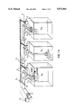
- FIG. 1A presents the procedure and the system according to the invention axonometrically and schematically.
- FIG. 1B presents the system of the invention schematically.
- FIG. 2 presents the schematically the duct systems, the control members and controller units associated with the system and the procedure.
- FIG. 3 presents the serial connection of the controller units.
- FIG. 4 presents another, parallel connecting mode of the controller units.
- FIG. 5 presents a control damper after the blower disposed in the trunk duct and an advantageous embodiment of its controller unit as block diagram.
- FIG. 6 presents as block diagram an advantageous embodiment of a blower controller units E p disposed in the trunk duct.
- FIG. 7 presents as block diagram an advantageous embodiment of the controller unit E of a control damper disposed in the zone duct.
- FIG. 8 presents a control member disposed in the incoming air duct C leading to a space to be air controlled and an advantageous embodiment of its controller unit, as block diagram.
- FIG. 1A is presented axonometrically and schematically the system and the apparatus system according to the invention.
- the air-conditioning system of the invention the most comprehensive embodiment thereof comprises at least one main duct and branch ducts branching therefrom, which are disposed to lead into rooms, spaces or equivalent to be air-conditioned, or to focussed ventilation points.
- air is removed from the above-mentioned points (broken line arrows) or fresh air is carried into said points (integral line arrows).
- At least one air-conditioning machine P is included to provide air flow.
- the main duct Z 1 comprises a control member S 1 to control the total air flow rate of the main duct.
- the control member S 1 has been disposed to a position before the branching points between the main duct and the branch ducts.
- Each branch duct C 1 .1,C 1 .1, 1 .1 is further provided with control members S 1 .1,S 1 .2,S 1 .3 controlling the air flow passing through the branch duct, and particularly the volumetric air flow rate.
- Both the control member of the main duct and the control members of the branch ducts comprise each a controller unit E 1 ;E 1 .2,E 1 .3.
- the controller unit E 1 of the main duct is placed on a higher level in the controlling hierarchy than the controller units E 1 .1,E 1 .2,E 1 .3 of the branch ducts.
- controller unit E 1 of the main duct has been disposed to govern and control the control members S 1 .1,S 1 .2,S 1 .3 of the branch ducts through their controller units E 1 .1,E 1 .2,E 1 .3.
- a data transfer connection exists between the controller unit of the control member of the main duct and the controller units of the control members of the branch ducts: either a wireless data transfer connection or said connection has been arranged through cables T or other equivalent data transfer buses.
- the set values are delivered from the controller unit E 1 of the control member of the main duct to the controller units E 1 .1,E 1 .2,E 1 .3 of the control members of the branch ducts.
- Said set values are given simultanously from the controller unit of the control member of the main duct to said controller units of the control members of the branch ducts.
- the set values are transmitted to all control members, to the controller units thereof; in addition to the control member of the main duct is transmitted a set value defined by the combination, irrespective of whether it is the same as or different from the one in an earlier setting time.
- the volumetric air flow rates required at times are defined on the basis of the air temperature and/or air quality and/or air noise levels and/or air pressure conditions or other similar factors. Said defining may be carried out in the course of a given, predeterminable period of time. Based on said air currents, a set value combination of the control members and the air conditioning machines is determined simultaneously. Thus, in the procedure of the invention the control members and the air-conditioning machines are set simultaneously to settings consistent with the set value combination. With said set values of the set value combination, the required volumetric air flow rates defined by calculation are realized to the air-conditioning targets and from the targets of the system.
- the set value combination comprises the set values defined by calculation for all control members and air-conditioning machines of the system.
- the setting data of the actuating members controlling the volumetric air flow rate of the control members are used either directly or indirectly.
- An air resistance coefficient may be given as a set value. Said air resistance coefficient may be given regarding the respective control member or a larger entity associated with the control member. In the form of a set value for machines producing air flow may also be given e.g. rpm data or equivalent control data of the apparatus changing the air flow rate.
- Determining a set value combination takes place in the control system employing an air-conditioning balancing calculation method known in itself in the art.
- the data required in controlling the control members and the air conditioning machines are stored advantageously in a separate memory of the controller unit of each control member and air-conditioning machine.
- the memory of each controller unit may comprise, for instance, an air resistance coefficient and governing data required in governing the control member associated therewith, said data setting the actuating means controlling the air flow of the control member to a setting defined by the air resistance coefficient.
- In the memory of each control member may also be stored other recorded data required in seting the control member, e.g. flow technology values of said control member.
- FIG. 1B presents the operation diagram of the system according to the invention.
- the system comprises a trunk duct R. From the trunk duct is branched a zone duct Z. From the zone duct Z branches further an incoming air duct C leading to a space to be air-conditioned, for instance to a room. Respectively, an outlet air duct C' leads out of the space to be air-conditioned to a zone duct Z' on the outlet side, being further connected to the trunk duct R' of the outlet side.
- the trunk duct R comprises an air-conditioning apparatus P, preferably a blower, and a control member S, preferably a control damper, placed after the air-conditioning apparatus P.
- an air-conditioning apparatus P preferably a blower
- a control member S preferably a control damper
- a control member S In the zone duct Z branching from the trunk duct R is located a control member S at the beginning of the zone duct, respectively a control member S is located in the incoming air duct C leading to the space to be air-conditioned.
- the control members may be e.g. control dampers.
- a control member S is also located in the zone duct Z' of the outlet side. They are advantageously control dampers.
- an air-conditioning apparatus P' causing the air to exit out from the room space.
- the air-conditioning apparatus is advantageously an outlet blower.
- On the outlet side of the outlet blower P' and on the drawing side of the incoming air blower P is located a mixing unit.
- the air to be removed from the space to be air-conditioned is presented by arrows L 2 .
- each control member S is controlled by control units E.
- the control units E are with data transfer connection interconnected through data transfer buses T. Respectively, the control units E are in data transfer connection to the control members S, to the setting apparatus thereof, through a governing member D.
- FIG. 2 is presented more in detail the air-conditioning system of the invention.
- the air-conditioning apparatus P is disposed into the trunk duct R.
- the zone ducts Z 1 ,Z 2 . . . Z n are branched from the trunk duct R.
- Each zone duct Z 1 ,Z 2 . . . Z n comprises a control member S at the beginning of the duct line.
- the zone duct Z 1 comprises a control member S 1
- the zone duct Z 2 comprises a control member S 2
- the zone duct Z n comprises a control member S n .
- the control members may be e.g. control dampers or other flow controlling actuating apparatus.
- the control member S 1 of the zone duct Z 1 is controlled by a control unit E 1 .
- the control member S 2 of the zone duct Z 2 is controlled by a control unit E 2 ; respectively, the control member S n of the zone duct Z n is controlled by a control unit E
- each zone duct Z 1 From each zone duct Z 1 , one or several incoming air ducts C are branched leading into the space to be air conditioned. Into the incoming air duct C leading into the space to be air-conditioned, a control member S controlling the air flow, for instance a control damper, has been disposed.
- a control member S controlling the air flow for instance a control damper
- a control member S 1 .1 leading into a space H 1 to be air-conditioned is disposed a control member S 1 .1, the opening set value whereof being controlled by a control unit E 1 .1.
- an incoming air duct C 1 .2 leading to a space H 2 to be air-conditioned comprises a control member S 1 .2 disposed in the duct, which is controlled by a control unit E 1 .2.
- a plurality of branch ducts C 11 , C 12 . . . C 21 ,C 22 may lead from each zone duct Z 1 ,Z 2 . . . into spaces H to be air-conditioned, being consistent with the number of the spaces on the zone duct which are to be air-conditioned.
- an outlet duct C' leading to one space to be air-conditioned.
- the outlet duct is connected to a zone duct 2' of the outlet side, which is further connected to the trunk duct R' of the outlet side.
- the trunk duct R' of the outlet side comprises an air-conditioning apparatus P', advantageously an outlet blower.
- the zone duct Z' comprises likewise a zone duct and a control member S 1 ' closing and opening the zone duct in the joining point of the zone duct of the trunk duct R' of the outlet side, said member being controlled by a control unit E 1 '.
- the outlet air line between the space to be air-conditioned and the zone duct Z 1 ' comprises a control member S 1 .1, controlled by a controller unit E 1 .1.
- Each space to be air-conditioned may comprise said apparatus arrangements of the outlet side. Also feasible is such an embodiment of the invention in which no ducts exist in the outlet side, but from the space to be air-conditioned the air is removed by the aid of overpressure produced by an air-conditioning apparatus P of the incoming air side, e.g. a blower.
- the space to be air-conditioned may thus be provided with an outlet duct directly out of doors.
- the control units of all control members S and apparatus P are interconnected to be in data transfer connection by the aid of a data bus T.
- governing between each controller unit and the setting means of the control member associated therewith has been arranged. Said governing is indicated in FIG. 2 by letter P.
- the controller unit E 1 of the control member S 1 of the zone Z 1 calculates on the basis of the specific graphs of the components and the design parameters of the system new setting data for all control members of the zone in a changed situation so that the air quantity of the space H is increased by 25% and the situation in other spaces of the zone remains the same.
- zone controller unit E 1 informs onwards to the controller unit E p of the air-conditioning apparatus P, which calculates the situation of the entire installation and determines a new set value of the apparatus unit P corresponding to the increased air quantity, for instance a new volumetric air rate which a test unit, e.g. a blower blows.
- a new set value of the apparatus unit P has been obtained from a computer pattern included in the controller unit E, the set values of all other control members are at the same time known and available for the control units of said control members controlling the air flow.
- the apparatus unit P transmits via its control units E p a change command which the zone controller units of the control members of the zone lines tranmit further to the controller units of the control members e.g. control dampers disposed into the ducts leading to the spaces to be air-conditioned.
- a simultaneous change is thus implemented in the entire system and as the only notable change remains the increase of the air quantity of the space H by the desired 25%.
- the free capacity may be directed and distributed to spaces which ask for it in the ratio of their needs and priority status.
- the air-conditioning procedure of the invention and the system of the procedure is thus guaranteed provision of an air quantity planned for all situations at the minimum pressure and minimum energy corresponding to each situation.
- the system also permits a space-specifically realized control and it permits an efficient and speedy isolation of a fire area in fire situations by altering the pressure conditions of the spaces to be air-conditioned.
- controller units of the installation are connected to the same data transfer bus T.
- the position of these controller units E in the hierarchy of the installation is solely determined by programs so that all units are able to receive and transmit data.
- the communication between the controller units E is divided physically into two separated planes A and B.
- plane A the communication takes place between the zone controller units E 1 ,E 2 ,E 3 and the controller unit E p of the apparatus P.
- plane B the data transfer communication takes place between each zone unit E 1 ,E 2 ,E 3 . . . E n and, subjected thereunder, the controller units E 1 .1,E 1 .2 . . . E 2 .1,E 2 .2 . . . of the control members leading to the spaces to be air-conditioned.
- An advantage in said system is low bus loading.
- the controller unit E p of the air-conditioning apparatus of the trunk line is further connected from the process plane to the rest of the data system X of the building.
- FIG. 5 presents a more detailed block diagram presentation on the control of an air-conditioning apparatus P, of the opening station of a control damper disposed advantageously into the trunk duct R after a blower.
- the controller unit E comprises in this design an actuating means 10 of a control damper, a pressure transmitter 12 disposed into the trunk duct after the control damper, said transmitter measuring air pressure in said part of the trunk duct R.
- the controller E consists further of a CPU 13 provided with a CPU section for calculations, a RAM/ROM memory section 13b for storing the data related to the programs and the process, output controls 13c, input signal connections 13d from the setting transmitter of the control damper and possibly for receiving data from other transmitters, and a serial connection bus 13e, as well as an A/D converter 13f.
- the data from the pressure transmitter 12 is directed along a data bus 14 to the CPU 13.
- the setting data of the control damper from the setting transmitter 11 is directed along a data transfer bus 15 to the CPU 13 of the controller unit, into its block 13f.
- From the block 13c, that is, from the outlet connection of the CPU is provided a governing step 16 for the actuating means 10 defining the setting of the control damper.
- FIG. 6 presents the control of the air-conditioning apparatus P, advantageously of a blower.
- the control unit E of the blower P comprises, as in FIG. 6, a frequency converter 17 converting the rpm of the blower P.
- the central governing part 19 of the controller E comprises the central functional components in the embodiment of the figure, corresponding to those in the design of FIG. 6.
- the CPU 19 comprises computer programs 19a, an output 19c of the memory block 9b, input connections 19d, a serial connection bus 19e, and an A/D converter 19f. From the pressure pick-up 18 an input signal is conducted along a data transfer bus 20 into the A/D converter section 19f of the CPU 19. From the output 19c of the CPU 19, a governing 21 is provided for the frequency converter 17 for producing an rpm set value signal of the blower P for the frequency converter.
- FIG. 7 presents the controller unit E of the control damper S disposed in the zone duct Z.
- the unit Z consists, as shown in the figure, of an actuating means 22 for the control damper with which the computer controls the position of the damper.
- a position pick-up 23 of the control damper is further connected to the CPU 24, which comprises programs 24a, a memory 24b, an output connection 24c, input connections 24d, a serial connection 24e, and an A/D converter unit 24f, to which the pick-up information from the pick-up 23 is carried along the bus 25.
- To the setting means of the control damper is transmitted control data through the control 26 from the output 24c of the CPU 24.
- FIG. 8 presents a control damper S used in the procedure of the invention, said control damper being disposed in the duct C leading to a space to be air-conditioned.
- the controller unit E of said control damper comprises the governing 27 of the setting of the control damper, a pick-up 28 indicating the position of the control damper, a temperature pick-up 29 inserted in the air-conditioning line, and a temperature pick-up 30 placed in the room space. From the pick-up 30 a data bus 31 is connected to the CPU 32 of the controller E. Respectively, from the temperature pick-up 29 a data bus 33 in the air duct C is connected to the CPU 32. From the position pick-up 28 a data bus 34 is connected to the CPU 32.
- the apparatus comprises furthermore a computer section, a CPU section, a memory section, and a governing message section.
- the apparatus comprises further a remote control means 36 by the aid of which a remote control centre can be transmitted wirelessly to the unit 32 for altering its set values or for reading wirelessly the temperature and/or setting values transmitted thereto.
Landscapes
- Engineering & Computer Science (AREA)
- Physics & Mathematics (AREA)
- Automation & Control Theory (AREA)
- General Physics & Mathematics (AREA)
- Combustion & Propulsion (AREA)
- Mechanical Engineering (AREA)
- General Engineering & Computer Science (AREA)
- Remote Sensing (AREA)
- Chemical & Material Sciences (AREA)
- Fluid Mechanics (AREA)
- Air Conditioning Control Device (AREA)
- Control Of El Displays (AREA)
- Inorganic Fibers (AREA)
- Catalysts (AREA)
- Duct Arrangements (AREA)
- Central Air Conditioning (AREA)
Applications Claiming Priority (2)
| Application Number | Priority Date | Filing Date | Title |
|---|---|---|---|
| FI890170 | 1989-01-13 | ||
| FI890170A FI88432C (fi) | 1989-01-13 | 1989-01-13 | Foerfarande foer reglering och uppraetthaollande av luftstroemmar och motsvarande i ventilationsanlaeggningar och ett ventilationssystem i enlighet med foerfarandet |
Publications (1)
| Publication Number | Publication Date |
|---|---|
| US5071065A true US5071065A (en) | 1991-12-10 |
Family
ID=8527717
Family Applications (1)
| Application Number | Title | Priority Date | Filing Date |
|---|---|---|---|
| US07/566,392 Expired - Lifetime US5071065A (en) | 1989-01-13 | 1990-01-11 | Procedure for controlling and maintaining air currents or equivalent in an air-conditioning installation, and an air-conditioning system according to said procedure |
Country Status (8)
| Country | Link |
|---|---|
| US (1) | US5071065A (de) |
| EP (1) | EP0404914B1 (de) |
| JP (1) | JPH03503207A (de) |
| AT (1) | ATE105069T1 (de) |
| DE (1) | DE69008432T2 (de) |
| ES (1) | ES2053172T3 (de) |
| FI (1) | FI88432C (de) |
| WO (1) | WO1990008293A1 (de) |
Cited By (64)
| Publication number | Priority date | Publication date | Assignee | Title |
|---|---|---|---|---|
| US5446677A (en) * | 1994-04-28 | 1995-08-29 | Johnson Service Company | Diagnostic system for use in an environment control network |
| DE4423336A1 (de) * | 1994-06-20 | 1995-12-21 | Bodo Zeschke | Steuerung einer Nachströmöffnung zur Vermeidung eines Raumunterdrucks im Aufstellungsraum eines schornsteingebundenen Heizgerätes |
| US5555195A (en) * | 1994-07-22 | 1996-09-10 | Johnson Service Company | Controller for use in an environment control network capable of storing diagnostic information |
| US5682329A (en) * | 1994-07-22 | 1997-10-28 | Johnson Service Company | On-line monitoring of controllers in an environment control network |
| US6108614A (en) * | 1993-01-22 | 2000-08-22 | Diablo Research Corporation | System and method for serial communication between a central unit and a plurality of remote units |
| US6243654B1 (en) | 1997-10-07 | 2001-06-05 | Telemonitor, Inc. | Transducer assembly with smart connector |
| EP1134509A1 (de) * | 2000-03-17 | 2001-09-19 | Stifab Farex AB | Verfahren und Anordnung zur Steuerung eines Belüftungssystems |
| WO2002066903A1 (en) * | 2001-02-16 | 2002-08-29 | Halton Oy | Method and equipment for automatic determination of flow resistance in the distribution network of an air-conditioning system |
| US20030051490A1 (en) * | 2000-11-22 | 2003-03-20 | Nagaraj Jayanth | Remote data acquisition system and method |
| US20050040248A1 (en) * | 2003-08-18 | 2005-02-24 | Wacker Paul C. | PDA configuration of thermostats |
| US6866203B2 (en) | 2003-02-26 | 2005-03-15 | Unico, Inc. | Method and apparatus for sizing an environmental control system |
| US20050156050A1 (en) * | 2004-01-20 | 2005-07-21 | Shah Rajendra K. | Method and system for automatically optimizing zone duct damper positions |
| US20050196285A1 (en) * | 2003-12-30 | 2005-09-08 | Nagaraj Jayanth | Compressor protection and diagnostic system |
| US7290398B2 (en) | 2003-08-25 | 2007-11-06 | Computer Process Controls, Inc. | Refrigeration control system |
| US20080142607A1 (en) * | 2006-12-19 | 2008-06-19 | Sanyo Electric Co., Ltd. | Air conditioning system and method of controlling the same |
| US7412842B2 (en) | 2004-04-27 | 2008-08-19 | Emerson Climate Technologies, Inc. | Compressor diagnostic and protection system |
| US7594407B2 (en) | 2005-10-21 | 2009-09-29 | Emerson Climate Technologies, Inc. | Monitoring refrigerant in a refrigeration system |
| US7596959B2 (en) | 2005-10-21 | 2009-10-06 | Emerson Retail Services, Inc. | Monitoring compressor performance in a refrigeration system |
| US20090255997A1 (en) * | 2008-04-13 | 2009-10-15 | Richard Goldmann | Apparatus and Method for Flexibly and Efficiently Varying Air Temperatures in Multiple Rooms |
| US7644591B2 (en) | 2001-05-03 | 2010-01-12 | Emerson Retail Services, Inc. | System for remote refrigeration monitoring and diagnostics |
| US7665315B2 (en) | 2005-10-21 | 2010-02-23 | Emerson Retail Services, Inc. | Proofing a refrigeration system operating state |
| US7752853B2 (en) | 2005-10-21 | 2010-07-13 | Emerson Retail Services, Inc. | Monitoring refrigerant in a refrigeration system |
| US7752854B2 (en) | 2005-10-21 | 2010-07-13 | Emerson Retail Services, Inc. | Monitoring a condenser in a refrigeration system |
| US20100305718A1 (en) * | 2009-05-29 | 2010-12-02 | Emerson Retail Services, Inc. | System and method for monitoring and evaluating equipment operating parameter modifications |
| US7885959B2 (en) | 2005-02-21 | 2011-02-08 | Computer Process Controls, Inc. | Enterprise controller display method |
| US7891573B2 (en) | 2006-03-03 | 2011-02-22 | Micro Metl Corporation | Methods and apparatuses for controlling air to a building |
| US20110160916A1 (en) * | 2009-12-24 | 2011-06-30 | Bahali Sumanta K | Fan speed control of rack devices where sum of device airflows is greater than maximum airflow of rack |
| US8160827B2 (en) | 2007-11-02 | 2012-04-17 | Emerson Climate Technologies, Inc. | Compressor sensor module |
| US8232860B2 (en) | 2005-10-21 | 2012-07-31 | Honeywell International Inc. | RFID reader for facility access control and authorization |
| CN1910405B (zh) * | 2004-01-20 | 2012-09-05 | 开利公司 | 自动优化区域风槽气闸位置的方法和系统 |
| US20120296485A1 (en) * | 2009-12-28 | 2012-11-22 | Hironori Kambara | Control device, power usage control system and control method |
| US8351350B2 (en) | 2007-05-28 | 2013-01-08 | Honeywell International Inc. | Systems and methods for configuring access control devices |
| US8393169B2 (en) | 2007-09-19 | 2013-03-12 | Emerson Climate Technologies, Inc. | Refrigeration monitoring system and method |
| US8495886B2 (en) | 2001-05-03 | 2013-07-30 | Emerson Climate Technologies Retail Solutions, Inc. | Model-based alarming |
| US8590325B2 (en) | 2006-07-19 | 2013-11-26 | Emerson Climate Technologies, Inc. | Protection and diagnostic module for a refrigeration system |
| US8598982B2 (en) | 2007-05-28 | 2013-12-03 | Honeywell International Inc. | Systems and methods for commissioning access control devices |
| US8700444B2 (en) | 2002-10-31 | 2014-04-15 | Emerson Retail Services Inc. | System for monitoring optimal equipment operating parameters |
| US8707414B2 (en) | 2010-01-07 | 2014-04-22 | Honeywell International Inc. | Systems and methods for location aware access control management |
| US8787725B2 (en) | 2010-11-11 | 2014-07-22 | Honeywell International Inc. | Systems and methods for managing video data |
| US8878931B2 (en) | 2009-03-04 | 2014-11-04 | Honeywell International Inc. | Systems and methods for managing video data |
| US8964338B2 (en) | 2012-01-11 | 2015-02-24 | Emerson Climate Technologies, Inc. | System and method for compressor motor protection |
| US8974573B2 (en) | 2004-08-11 | 2015-03-10 | Emerson Climate Technologies, Inc. | Method and apparatus for monitoring a refrigeration-cycle system |
| US9019070B2 (en) | 2009-03-19 | 2015-04-28 | Honeywell International Inc. | Systems and methods for managing access control devices |
| US9140728B2 (en) | 2007-11-02 | 2015-09-22 | Emerson Climate Technologies, Inc. | Compressor sensor module |
| US9280365B2 (en) | 2009-12-17 | 2016-03-08 | Honeywell International Inc. | Systems and methods for managing configuration data at disconnected remote devices |
| US9285802B2 (en) | 2011-02-28 | 2016-03-15 | Emerson Electric Co. | Residential solutions HVAC monitoring and diagnosis |
| US9310094B2 (en) | 2007-07-30 | 2016-04-12 | Emerson Climate Technologies, Inc. | Portable method and apparatus for monitoring refrigerant-cycle systems |
| US9310439B2 (en) | 2012-09-25 | 2016-04-12 | Emerson Climate Technologies, Inc. | Compressor having a control and diagnostic module |
| US9344684B2 (en) | 2011-08-05 | 2016-05-17 | Honeywell International Inc. | Systems and methods configured to enable content sharing between client terminals of a digital video management system |
| US9480177B2 (en) | 2012-07-27 | 2016-10-25 | Emerson Climate Technologies, Inc. | Compressor protection module |
| US9551504B2 (en) | 2013-03-15 | 2017-01-24 | Emerson Electric Co. | HVAC system remote monitoring and diagnosis |
| US9638436B2 (en) | 2013-03-15 | 2017-05-02 | Emerson Electric Co. | HVAC system remote monitoring and diagnosis |
| US9704313B2 (en) | 2008-09-30 | 2017-07-11 | Honeywell International Inc. | Systems and methods for interacting with access control devices |
| US9765979B2 (en) | 2013-04-05 | 2017-09-19 | Emerson Climate Technologies, Inc. | Heat-pump system with refrigerant charge diagnostics |
| US9823632B2 (en) | 2006-09-07 | 2017-11-21 | Emerson Climate Technologies, Inc. | Compressor data module |
| US9894261B2 (en) | 2011-06-24 | 2018-02-13 | Honeywell International Inc. | Systems and methods for presenting digital video management system information via a user-customizable hierarchical tree interface |
| US10038872B2 (en) | 2011-08-05 | 2018-07-31 | Honeywell International Inc. | Systems and methods for managing video data |
| US10041713B1 (en) | 1999-08-20 | 2018-08-07 | Hudson Technologies, Inc. | Method and apparatus for measuring and improving efficiency in refrigeration systems |
| US10362273B2 (en) | 2011-08-05 | 2019-07-23 | Honeywell International Inc. | Systems and methods for managing video data |
| US10436488B2 (en) | 2002-12-09 | 2019-10-08 | Hudson Technologies Inc. | Method and apparatus for optimizing refrigeration systems |
| US10488090B2 (en) | 2013-03-15 | 2019-11-26 | Emerson Climate Technologies, Inc. | System for refrigerant charge verification |
| US10523903B2 (en) | 2013-10-30 | 2019-12-31 | Honeywell International Inc. | Computer implemented systems frameworks and methods configured for enabling review of incident data |
| US11384951B2 (en) * | 2017-06-14 | 2022-07-12 | Joseph A. Ross | Zoning system for air conditioning (HVAC) equipment |
| US12339023B2 (en) | 2017-06-14 | 2025-06-24 | Joseph A. Ross | Zoning system for air conditioning (HVAC) equipment |
Families Citing this family (7)
| Publication number | Priority date | Publication date | Assignee | Title |
|---|---|---|---|---|
| US5180102A (en) * | 1991-08-12 | 1993-01-19 | Carrier Corporation | Temperature control system for zoned space |
| US5361982A (en) * | 1993-07-12 | 1994-11-08 | Johnson Service Company | Temperature control system having central control for thermostats |
| US5540619A (en) * | 1995-01-06 | 1996-07-30 | Landis & Gyr Powers, Inc. | Control of prime mover in HVAC distribution system |
| US5573181A (en) * | 1995-01-06 | 1996-11-12 | Landis & Gyr Powers, Inc. | Global control of HVAC distribution system |
| US5705734A (en) * | 1996-07-17 | 1998-01-06 | Landis & Staefa, Inc. | Automated branch flow calibration in a HVAC distribution system |
| CN100529567C (zh) * | 2004-01-20 | 2009-08-19 | 开利公司 | 由供暖、通风与空调系统内的区域来确定相对管道尺寸的方法及系统 |
| DE102016201745A1 (de) | 2016-02-05 | 2017-08-10 | Vaillant Gmbh | Softsensor zur Identifikation und Regelung oder Steuerung eines Lüftungssystems |
Citations (10)
| Publication number | Priority date | Publication date | Assignee | Title |
|---|---|---|---|---|
| DE2715835A1 (de) * | 1977-04-05 | 1978-10-19 | Herbst Donald | Steuerungsanordnung fuer klimaanlagen mit variablem zuluft-volumen |
| US4205381A (en) * | 1977-08-31 | 1980-05-27 | United Technologies Corporation | Energy conservative control of heating, ventilating, and air conditioning (HVAC) systems |
| DE3124966A1 (de) * | 1981-06-22 | 1983-01-13 | Dr. Walter Herbst Ingenieurgesellschaft mbH & Co, 1000 Berlin | Steuer- und ueberwachungssystem fuer haustechnische anlagen |
| US4497031A (en) * | 1982-07-26 | 1985-01-29 | Johnson Service Company | Direct digital control apparatus for automated monitoring and control of building systems |
| US4616325A (en) * | 1983-06-17 | 1986-10-07 | Johnson Service Company | Zone condition controller and method of using same |
| US4630221A (en) * | 1983-06-17 | 1986-12-16 | Johnson Service Company | Zone condition controller and method of using same |
| EP0238979A2 (de) * | 1986-03-25 | 1987-09-30 | Siemens Aktiengesellschaft | Anordnung zum Regeln von Temperatur und Feuchte |
| GB2190216A (en) * | 1986-04-10 | 1987-11-11 | Daikin Ind Ltd | Controlling air conditioning system |
| US4821526A (en) * | 1985-08-22 | 1989-04-18 | Mitsubishi Denki Kabushiki Kaisha | Air conditioning apparatus |
| US4843084A (en) * | 1987-02-12 | 1989-06-27 | Parker Electronics, Inc. | Thermostat control system |
Family Cites Families (2)
| Publication number | Priority date | Publication date | Assignee | Title |
|---|---|---|---|---|
| JPS61107034A (ja) * | 1984-10-31 | 1986-05-24 | Yamatake Honeywell Co Ltd | 空調制御方法 |
| JPS62194159A (ja) * | 1986-02-20 | 1987-08-26 | Mitsubishi Electric Corp | ダクト式空気調和機 |
-
1989
- 1989-01-13 FI FI890170A patent/FI88432C/fi active IP Right Grant
-
1990
- 1990-01-11 ES ES90901608T patent/ES2053172T3/es not_active Expired - Lifetime
- 1990-01-11 US US07/566,392 patent/US5071065A/en not_active Expired - Lifetime
- 1990-01-11 DE DE69008432T patent/DE69008432T2/de not_active Expired - Fee Related
- 1990-01-11 AT AT9090901608T patent/ATE105069T1/de not_active IP Right Cessation
- 1990-01-11 WO PCT/FI1990/000010 patent/WO1990008293A1/en not_active Ceased
- 1990-01-11 JP JP2501743A patent/JPH03503207A/ja active Pending
- 1990-01-11 EP EP90901608A patent/EP0404914B1/de not_active Expired - Lifetime
Patent Citations (10)
| Publication number | Priority date | Publication date | Assignee | Title |
|---|---|---|---|---|
| DE2715835A1 (de) * | 1977-04-05 | 1978-10-19 | Herbst Donald | Steuerungsanordnung fuer klimaanlagen mit variablem zuluft-volumen |
| US4205381A (en) * | 1977-08-31 | 1980-05-27 | United Technologies Corporation | Energy conservative control of heating, ventilating, and air conditioning (HVAC) systems |
| DE3124966A1 (de) * | 1981-06-22 | 1983-01-13 | Dr. Walter Herbst Ingenieurgesellschaft mbH & Co, 1000 Berlin | Steuer- und ueberwachungssystem fuer haustechnische anlagen |
| US4497031A (en) * | 1982-07-26 | 1985-01-29 | Johnson Service Company | Direct digital control apparatus for automated monitoring and control of building systems |
| US4616325A (en) * | 1983-06-17 | 1986-10-07 | Johnson Service Company | Zone condition controller and method of using same |
| US4630221A (en) * | 1983-06-17 | 1986-12-16 | Johnson Service Company | Zone condition controller and method of using same |
| US4821526A (en) * | 1985-08-22 | 1989-04-18 | Mitsubishi Denki Kabushiki Kaisha | Air conditioning apparatus |
| EP0238979A2 (de) * | 1986-03-25 | 1987-09-30 | Siemens Aktiengesellschaft | Anordnung zum Regeln von Temperatur und Feuchte |
| GB2190216A (en) * | 1986-04-10 | 1987-11-11 | Daikin Ind Ltd | Controlling air conditioning system |
| US4843084A (en) * | 1987-02-12 | 1989-06-27 | Parker Electronics, Inc. | Thermostat control system |
Cited By (125)
| Publication number | Priority date | Publication date | Assignee | Title |
|---|---|---|---|---|
| US6108614A (en) * | 1993-01-22 | 2000-08-22 | Diablo Research Corporation | System and method for serial communication between a central unit and a plurality of remote units |
| WO1995030114A1 (en) * | 1994-04-28 | 1995-11-09 | Johnson Service Company | Diagnostic system for use in an environment control network |
| US5446677A (en) * | 1994-04-28 | 1995-08-29 | Johnson Service Company | Diagnostic system for use in an environment control network |
| DE4423336A1 (de) * | 1994-06-20 | 1995-12-21 | Bodo Zeschke | Steuerung einer Nachströmöffnung zur Vermeidung eines Raumunterdrucks im Aufstellungsraum eines schornsteingebundenen Heizgerätes |
| US5555195A (en) * | 1994-07-22 | 1996-09-10 | Johnson Service Company | Controller for use in an environment control network capable of storing diagnostic information |
| US5682329A (en) * | 1994-07-22 | 1997-10-28 | Johnson Service Company | On-line monitoring of controllers in an environment control network |
| US6243654B1 (en) | 1997-10-07 | 2001-06-05 | Telemonitor, Inc. | Transducer assembly with smart connector |
| US10041713B1 (en) | 1999-08-20 | 2018-08-07 | Hudson Technologies, Inc. | Method and apparatus for measuring and improving efficiency in refrigeration systems |
| EP1134509A1 (de) * | 2000-03-17 | 2001-09-19 | Stifab Farex AB | Verfahren und Anordnung zur Steuerung eines Belüftungssystems |
| US6823680B2 (en) | 2000-11-22 | 2004-11-30 | Copeland Corporation | Remote data acquisition system and method |
| US20040206096A1 (en) * | 2000-11-22 | 2004-10-21 | Nagaraj Jayanth | Remote data acquisition system and method |
| US20030051490A1 (en) * | 2000-11-22 | 2003-03-20 | Nagaraj Jayanth | Remote data acquisition system and method |
| US20050000235A1 (en) * | 2000-11-22 | 2005-01-06 | Nagaraj Jayanth | Remote data acquisition system and method |
| US7412839B2 (en) | 2000-11-22 | 2008-08-19 | Emerson Climate Technologies, Inc. | Remote data acquisition system and method |
| US7174728B2 (en) | 2000-11-22 | 2007-02-13 | Emerson Climate Technologies, Inc. | Remote data acquisition system and method |
| US20050166610A1 (en) * | 2000-11-22 | 2005-08-04 | Nagaraj Jayanth | Cooling system diagnostic system apparatus and method |
| WO2002066903A1 (en) * | 2001-02-16 | 2002-08-29 | Halton Oy | Method and equipment for automatic determination of flow resistance in the distribution network of an air-conditioning system |
| US7644591B2 (en) | 2001-05-03 | 2010-01-12 | Emerson Retail Services, Inc. | System for remote refrigeration monitoring and diagnostics |
| US8065886B2 (en) | 2001-05-03 | 2011-11-29 | Emerson Retail Services, Inc. | Refrigeration system energy monitoring and diagnostics |
| US8495886B2 (en) | 2001-05-03 | 2013-07-30 | Emerson Climate Technologies Retail Solutions, Inc. | Model-based alarming |
| US8316658B2 (en) | 2001-05-03 | 2012-11-27 | Emerson Climate Technologies Retail Solutions, Inc. | Refrigeration system energy monitoring and diagnostics |
| US8700444B2 (en) | 2002-10-31 | 2014-04-15 | Emerson Retail Services Inc. | System for monitoring optimal equipment operating parameters |
| US10436488B2 (en) | 2002-12-09 | 2019-10-08 | Hudson Technologies Inc. | Method and apparatus for optimizing refrigeration systems |
| US6866203B2 (en) | 2003-02-26 | 2005-03-15 | Unico, Inc. | Method and apparatus for sizing an environmental control system |
| US20050040248A1 (en) * | 2003-08-18 | 2005-02-24 | Wacker Paul C. | PDA configuration of thermostats |
| US7055759B2 (en) * | 2003-08-18 | 2006-06-06 | Honeywell International Inc. | PDA configuration of thermostats |
| US7290398B2 (en) | 2003-08-25 | 2007-11-06 | Computer Process Controls, Inc. | Refrigeration control system |
| US20060182635A1 (en) * | 2003-12-30 | 2006-08-17 | Nagaraj Jayanth | Compressor protection and diagnostic system |
| US7648342B2 (en) | 2003-12-30 | 2010-01-19 | Emerson Climate Technologies, Inc. | Compressor protection and diagnostic system |
| US7290989B2 (en) | 2003-12-30 | 2007-11-06 | Emerson Climate Technologies, Inc. | Compressor protection and diagnostic system |
| US20060222507A1 (en) * | 2003-12-30 | 2006-10-05 | Nagaraj Jayanth | Compressor protection and diagnostic system |
| US7491034B2 (en) | 2003-12-30 | 2009-02-17 | Emerson Climate Technologies, Inc. | Compressor protection and diagnostic system |
| US20050196285A1 (en) * | 2003-12-30 | 2005-09-08 | Nagaraj Jayanth | Compressor protection and diagnostic system |
| US20050156050A1 (en) * | 2004-01-20 | 2005-07-21 | Shah Rajendra K. | Method and system for automatically optimizing zone duct damper positions |
| US7017827B2 (en) * | 2004-01-20 | 2006-03-28 | Carrier Corporation | Method and system for automatically optimizing zone duct damper positions |
| CN1910405B (zh) * | 2004-01-20 | 2012-09-05 | 开利公司 | 自动优化区域风槽气闸位置的方法和系统 |
| US7412842B2 (en) | 2004-04-27 | 2008-08-19 | Emerson Climate Technologies, Inc. | Compressor diagnostic and protection system |
| US9669498B2 (en) | 2004-04-27 | 2017-06-06 | Emerson Climate Technologies, Inc. | Compressor diagnostic and protection system and method |
| US9121407B2 (en) | 2004-04-27 | 2015-09-01 | Emerson Climate Technologies, Inc. | Compressor diagnostic and protection system and method |
| US10335906B2 (en) | 2004-04-27 | 2019-07-02 | Emerson Climate Technologies, Inc. | Compressor diagnostic and protection system and method |
| US7484376B2 (en) | 2004-04-27 | 2009-02-03 | Emerson Climate Technologies, Inc. | Compressor diagnostic and protection system and method |
| US7878006B2 (en) | 2004-04-27 | 2011-02-01 | Emerson Climate Technologies, Inc. | Compressor diagnostic and protection system and method |
| US8474278B2 (en) | 2004-04-27 | 2013-07-02 | Emerson Climate Technologies, Inc. | Compressor diagnostic and protection system and method |
| US7458223B2 (en) | 2004-04-27 | 2008-12-02 | Emerson Climate Technologies, Inc. | Compressor configuration system and method |
| US7905098B2 (en) | 2004-04-27 | 2011-03-15 | Emerson Climate Technologies, Inc. | Compressor diagnostic and protection system and method |
| WO2006016989A1 (en) * | 2004-07-13 | 2006-02-16 | Carrier Corporation | Method and system for automatically optimizing zone duct damper positions |
| US9690307B2 (en) | 2004-08-11 | 2017-06-27 | Emerson Climate Technologies, Inc. | Method and apparatus for monitoring refrigeration-cycle systems |
| US9081394B2 (en) | 2004-08-11 | 2015-07-14 | Emerson Climate Technologies, Inc. | Method and apparatus for monitoring a refrigeration-cycle system |
| US8974573B2 (en) | 2004-08-11 | 2015-03-10 | Emerson Climate Technologies, Inc. | Method and apparatus for monitoring a refrigeration-cycle system |
| US9017461B2 (en) | 2004-08-11 | 2015-04-28 | Emerson Climate Technologies, Inc. | Method and apparatus for monitoring a refrigeration-cycle system |
| US9023136B2 (en) | 2004-08-11 | 2015-05-05 | Emerson Climate Technologies, Inc. | Method and apparatus for monitoring a refrigeration-cycle system |
| US9021819B2 (en) | 2004-08-11 | 2015-05-05 | Emerson Climate Technologies, Inc. | Method and apparatus for monitoring a refrigeration-cycle system |
| US9046900B2 (en) | 2004-08-11 | 2015-06-02 | Emerson Climate Technologies, Inc. | Method and apparatus for monitoring refrigeration-cycle systems |
| US9086704B2 (en) | 2004-08-11 | 2015-07-21 | Emerson Climate Technologies, Inc. | Method and apparatus for monitoring a refrigeration-cycle system |
| US10558229B2 (en) | 2004-08-11 | 2020-02-11 | Emerson Climate Technologies Inc. | Method and apparatus for monitoring refrigeration-cycle systems |
| US9304521B2 (en) | 2004-08-11 | 2016-04-05 | Emerson Climate Technologies, Inc. | Air filter monitoring system |
| US7885959B2 (en) | 2005-02-21 | 2011-02-08 | Computer Process Controls, Inc. | Enterprise controller display method |
| US7885961B2 (en) | 2005-02-21 | 2011-02-08 | Computer Process Controls, Inc. | Enterprise control and monitoring system and method |
| US7752853B2 (en) | 2005-10-21 | 2010-07-13 | Emerson Retail Services, Inc. | Monitoring refrigerant in a refrigeration system |
| US7594407B2 (en) | 2005-10-21 | 2009-09-29 | Emerson Climate Technologies, Inc. | Monitoring refrigerant in a refrigeration system |
| US8941464B2 (en) | 2005-10-21 | 2015-01-27 | Honeywell International Inc. | Authorization system and a method of authorization |
| US7752854B2 (en) | 2005-10-21 | 2010-07-13 | Emerson Retail Services, Inc. | Monitoring a condenser in a refrigeration system |
| US7665315B2 (en) | 2005-10-21 | 2010-02-23 | Emerson Retail Services, Inc. | Proofing a refrigeration system operating state |
| US8232860B2 (en) | 2005-10-21 | 2012-07-31 | Honeywell International Inc. | RFID reader for facility access control and authorization |
| US7596959B2 (en) | 2005-10-21 | 2009-10-06 | Emerson Retail Services, Inc. | Monitoring compressor performance in a refrigeration system |
| US7891573B2 (en) | 2006-03-03 | 2011-02-22 | Micro Metl Corporation | Methods and apparatuses for controlling air to a building |
| US8590325B2 (en) | 2006-07-19 | 2013-11-26 | Emerson Climate Technologies, Inc. | Protection and diagnostic module for a refrigeration system |
| US9885507B2 (en) | 2006-07-19 | 2018-02-06 | Emerson Climate Technologies, Inc. | Protection and diagnostic module for a refrigeration system |
| US9823632B2 (en) | 2006-09-07 | 2017-11-21 | Emerson Climate Technologies, Inc. | Compressor data module |
| US20080142607A1 (en) * | 2006-12-19 | 2008-06-19 | Sanyo Electric Co., Ltd. | Air conditioning system and method of controlling the same |
| US8351350B2 (en) | 2007-05-28 | 2013-01-08 | Honeywell International Inc. | Systems and methods for configuring access control devices |
| US8598982B2 (en) | 2007-05-28 | 2013-12-03 | Honeywell International Inc. | Systems and methods for commissioning access control devices |
| US10352602B2 (en) | 2007-07-30 | 2019-07-16 | Emerson Climate Technologies, Inc. | Portable method and apparatus for monitoring refrigerant-cycle systems |
| US9310094B2 (en) | 2007-07-30 | 2016-04-12 | Emerson Climate Technologies, Inc. | Portable method and apparatus for monitoring refrigerant-cycle systems |
| US9651286B2 (en) | 2007-09-19 | 2017-05-16 | Emerson Climate Technologies, Inc. | Refrigeration monitoring system and method |
| US8393169B2 (en) | 2007-09-19 | 2013-03-12 | Emerson Climate Technologies, Inc. | Refrigeration monitoring system and method |
| US8335657B2 (en) | 2007-11-02 | 2012-12-18 | Emerson Climate Technologies, Inc. | Compressor sensor module |
| US10458404B2 (en) | 2007-11-02 | 2019-10-29 | Emerson Climate Technologies, Inc. | Compressor sensor module |
| US9140728B2 (en) | 2007-11-02 | 2015-09-22 | Emerson Climate Technologies, Inc. | Compressor sensor module |
| US9194894B2 (en) | 2007-11-02 | 2015-11-24 | Emerson Climate Technologies, Inc. | Compressor sensor module |
| US8160827B2 (en) | 2007-11-02 | 2012-04-17 | Emerson Climate Technologies, Inc. | Compressor sensor module |
| US20090255997A1 (en) * | 2008-04-13 | 2009-10-15 | Richard Goldmann | Apparatus and Method for Flexibly and Efficiently Varying Air Temperatures in Multiple Rooms |
| US9704313B2 (en) | 2008-09-30 | 2017-07-11 | Honeywell International Inc. | Systems and methods for interacting with access control devices |
| US8878931B2 (en) | 2009-03-04 | 2014-11-04 | Honeywell International Inc. | Systems and methods for managing video data |
| US9019070B2 (en) | 2009-03-19 | 2015-04-28 | Honeywell International Inc. | Systems and methods for managing access control devices |
| US20100305718A1 (en) * | 2009-05-29 | 2010-12-02 | Emerson Retail Services, Inc. | System and method for monitoring and evaluating equipment operating parameter modifications |
| US9395711B2 (en) | 2009-05-29 | 2016-07-19 | Emerson Climate Technologies Retail Solutions, Inc. | System and method for monitoring and evaluating equipment operating parameter modifications |
| US8761908B2 (en) | 2009-05-29 | 2014-06-24 | Emerson Climate Technologies Retail Solutions, Inc. | System and method for monitoring and evaluating equipment operating parameter modifications |
| US8473106B2 (en) | 2009-05-29 | 2013-06-25 | Emerson Climate Technologies Retail Solutions, Inc. | System and method for monitoring and evaluating equipment operating parameter modifications |
| US9280365B2 (en) | 2009-12-17 | 2016-03-08 | Honeywell International Inc. | Systems and methods for managing configuration data at disconnected remote devices |
| US20110160916A1 (en) * | 2009-12-24 | 2011-06-30 | Bahali Sumanta K | Fan speed control of rack devices where sum of device airflows is greater than maximum airflow of rack |
| US8805590B2 (en) * | 2009-12-24 | 2014-08-12 | International Business Machines Corporation | Fan speed control of rack devices where sum of device airflows is greater than maximum airflow of rack |
| US9065294B2 (en) * | 2009-12-28 | 2015-06-23 | Sharp Kabushiki Kaisha | Control device, power usage control system and control method |
| US20120296485A1 (en) * | 2009-12-28 | 2012-11-22 | Hironori Kambara | Control device, power usage control system and control method |
| US8707414B2 (en) | 2010-01-07 | 2014-04-22 | Honeywell International Inc. | Systems and methods for location aware access control management |
| US8787725B2 (en) | 2010-11-11 | 2014-07-22 | Honeywell International Inc. | Systems and methods for managing video data |
| US9703287B2 (en) | 2011-02-28 | 2017-07-11 | Emerson Electric Co. | Remote HVAC monitoring and diagnosis |
| US10234854B2 (en) | 2011-02-28 | 2019-03-19 | Emerson Electric Co. | Remote HVAC monitoring and diagnosis |
| US9285802B2 (en) | 2011-02-28 | 2016-03-15 | Emerson Electric Co. | Residential solutions HVAC monitoring and diagnosis |
| US10884403B2 (en) | 2011-02-28 | 2021-01-05 | Emerson Electric Co. | Remote HVAC monitoring and diagnosis |
| US9894261B2 (en) | 2011-06-24 | 2018-02-13 | Honeywell International Inc. | Systems and methods for presenting digital video management system information via a user-customizable hierarchical tree interface |
| US9344684B2 (en) | 2011-08-05 | 2016-05-17 | Honeywell International Inc. | Systems and methods configured to enable content sharing between client terminals of a digital video management system |
| US10038872B2 (en) | 2011-08-05 | 2018-07-31 | Honeywell International Inc. | Systems and methods for managing video data |
| US10863143B2 (en) | 2011-08-05 | 2020-12-08 | Honeywell International Inc. | Systems and methods for managing video data |
| US10362273B2 (en) | 2011-08-05 | 2019-07-23 | Honeywell International Inc. | Systems and methods for managing video data |
| US8964338B2 (en) | 2012-01-11 | 2015-02-24 | Emerson Climate Technologies, Inc. | System and method for compressor motor protection |
| US9590413B2 (en) | 2012-01-11 | 2017-03-07 | Emerson Climate Technologies, Inc. | System and method for compressor motor protection |
| US9876346B2 (en) | 2012-01-11 | 2018-01-23 | Emerson Climate Technologies, Inc. | System and method for compressor motor protection |
| US9480177B2 (en) | 2012-07-27 | 2016-10-25 | Emerson Climate Technologies, Inc. | Compressor protection module |
| US10028399B2 (en) | 2012-07-27 | 2018-07-17 | Emerson Climate Technologies, Inc. | Compressor protection module |
| US10485128B2 (en) | 2012-07-27 | 2019-11-19 | Emerson Climate Technologies, Inc. | Compressor protection module |
| US9762168B2 (en) | 2012-09-25 | 2017-09-12 | Emerson Climate Technologies, Inc. | Compressor having a control and diagnostic module |
| US9310439B2 (en) | 2012-09-25 | 2016-04-12 | Emerson Climate Technologies, Inc. | Compressor having a control and diagnostic module |
| US9551504B2 (en) | 2013-03-15 | 2017-01-24 | Emerson Electric Co. | HVAC system remote monitoring and diagnosis |
| US9638436B2 (en) | 2013-03-15 | 2017-05-02 | Emerson Electric Co. | HVAC system remote monitoring and diagnosis |
| US10488090B2 (en) | 2013-03-15 | 2019-11-26 | Emerson Climate Technologies, Inc. | System for refrigerant charge verification |
| US10274945B2 (en) | 2013-03-15 | 2019-04-30 | Emerson Electric Co. | HVAC system remote monitoring and diagnosis |
| US10775084B2 (en) | 2013-03-15 | 2020-09-15 | Emerson Climate Technologies, Inc. | System for refrigerant charge verification |
| US10443863B2 (en) | 2013-04-05 | 2019-10-15 | Emerson Climate Technologies, Inc. | Method of monitoring charge condition of heat pump system |
| US10060636B2 (en) | 2013-04-05 | 2018-08-28 | Emerson Climate Technologies, Inc. | Heat pump system with refrigerant charge diagnostics |
| US9765979B2 (en) | 2013-04-05 | 2017-09-19 | Emerson Climate Technologies, Inc. | Heat-pump system with refrigerant charge diagnostics |
| US10523903B2 (en) | 2013-10-30 | 2019-12-31 | Honeywell International Inc. | Computer implemented systems frameworks and methods configured for enabling review of incident data |
| US11523088B2 (en) | 2013-10-30 | 2022-12-06 | Honeywell Interntional Inc. | Computer implemented systems frameworks and methods configured for enabling review of incident data |
| US11384951B2 (en) * | 2017-06-14 | 2022-07-12 | Joseph A. Ross | Zoning system for air conditioning (HVAC) equipment |
| US12339023B2 (en) | 2017-06-14 | 2025-06-24 | Joseph A. Ross | Zoning system for air conditioning (HVAC) equipment |
Also Published As
| Publication number | Publication date |
|---|---|
| JPH03503207A (ja) | 1991-07-18 |
| DE69008432D1 (de) | 1994-06-01 |
| ATE105069T1 (de) | 1994-05-15 |
| FI88432B (fi) | 1993-01-29 |
| WO1990008293A1 (en) | 1990-07-26 |
| FI890170A7 (fi) | 1990-07-14 |
| FI88432C (fi) | 1993-05-10 |
| ES2053172T3 (es) | 1994-07-16 |
| EP0404914B1 (de) | 1994-04-27 |
| DE69008432T2 (de) | 1994-08-25 |
| FI890170A0 (fi) | 1989-01-13 |
| EP0404914A1 (de) | 1991-01-02 |
Similar Documents
| Publication | Publication Date | Title |
|---|---|---|
| WO1990008293A1 (en) | Procedure for controlling and maintaining air currents or equivalent in an air-conditioning installation, and an air-conditioning system according to said procedure | |
| CN1910527B (zh) | 分区域供暖、通风与空调系统的正确安装的检验方法 | |
| US5791408A (en) | Air handling unit including control system that prevents outside air from entering the unit through an exhaust air damper | |
| EP1950505B1 (de) | System zur Steuerung des Bedarfs einer Multityp-Klimaanlage | |
| CA2384899A1 (en) | Control system with communication function and facility control system | |
| CN100588881C (zh) | 可进行群组控制的空调系统及其操作方法 | |
| JPH01114657A (ja) | 空調制御装置 | |
| CN107101348A (zh) | 空调多联机组的室内、外机通讯方法、装置及空调机组 | |
| CN207635514U (zh) | 空调控制系统 | |
| JP3206476B2 (ja) | 空気調和装置の伝送制御装置 | |
| JP2003042522A (ja) | 制御システム | |
| US12375125B2 (en) | Methods and systems for data communications in HVAC systems | |
| JPH0587378A (ja) | 空気調和装置 | |
| JP3859293B2 (ja) | 空調システム | |
| JP2536234B2 (ja) | 空気調和装置 | |
| JP2518386B2 (ja) | 空気調和装置 | |
| JP2624319B2 (ja) | 空気調和機の換気運転制御装置 | |
| JP3334069B2 (ja) | Vav制御方法 | |
| GB2235551A (en) | Air conditioning | |
| JPH04203740A (ja) | マルチエアコン | |
| JP3198840B2 (ja) | 空気調和装置の伝送装置 | |
| JPH03177735A (ja) | 空気調和機 | |
| KR20070072264A (ko) | 멀티공조 중앙제어시스템 및 그의 메뉴구현방법 | |
| KR20050107087A (ko) | 멀티형 공기조화 시스템 | |
| JP3093426B2 (ja) | 空気調和機の制御装置 |
Legal Events
| Date | Code | Title | Description |
|---|---|---|---|
| AS | Assignment |
Owner name: HALTON OY, FINLAND Free format text: ASSIGNMENT OF ASSIGNORS INTEREST.;ASSIGNORS:AALTO, ERKKI;MATTILA, TIMO;NIEMELA, MERTSI;AND OTHERS;REEL/FRAME:005453/0336;SIGNING DATES FROM 19900629 TO 19900731 |
|
| STCF | Information on status: patent grant |
Free format text: PATENTED CASE |
|
| FEPP | Fee payment procedure |
Free format text: PAYOR NUMBER ASSIGNED (ORIGINAL EVENT CODE: ASPN); ENTITY STATUS OF PATENT OWNER: LARGE ENTITY |
|
| FPAY | Fee payment |
Year of fee payment: 4 |
|
| FPAY | Fee payment |
Year of fee payment: 8 |
|
| FPAY | Fee payment |
Year of fee payment: 12 |