US5099474A - Digital exchange and its control method - Google Patents
Digital exchange and its control method Download PDFInfo
- Publication number
- US5099474A US5099474A US07/454,597 US45459789A US5099474A US 5099474 A US5099474 A US 5099474A US 45459789 A US45459789 A US 45459789A US 5099474 A US5099474 A US 5099474A
- Authority
- US
- United States
- Prior art keywords
- clock
- digital
- signal
- line
- circuit
- Prior art date
- Legal status (The legal status is an assumption and is not a legal conclusion. Google has not performed a legal analysis and makes no representation as to the accuracy of the status listed.)
- Expired - Lifetime
Links
Images


Classifications
-
- H—ELECTRICITY
- H04—ELECTRIC COMMUNICATION TECHNIQUE
- H04J—MULTIPLEX COMMUNICATION
- H04J3/00—Time-division multiplex systems
- H04J3/02—Details
- H04J3/06—Synchronising arrangements
- H04J3/0635—Clock or time synchronisation in a network
- H04J3/0685—Clock or time synchronisation in a node; Intranode synchronisation
- H04J3/0688—Change of the master or reference, e.g. take-over or failure of the master
-
- H—ELECTRICITY
- H04—ELECTRIC COMMUNICATION TECHNIQUE
- H04Q—SELECTING
- H04Q11/00—Selecting arrangements for multiplex systems
- H04Q11/04—Selecting arrangements for multiplex systems for time-division multiplexing
Definitions
- the present invention relates to an improvement in a digital exchange having a plurality of digital trunks connected to digital lines and to an improvement in a control method thereof and, more particularly, to a digital exchange which can suppress the failure of the exchange even when an abnormality or abnormalities occur in any of digital trunks from which clocks are extracted through the associated digital lines so long as at least one of the digital trunks is normal and also to a control method thereof.
- An exchange generally functions to exchange interconnection between a plurality of extension telephone sets, connection of the extention telephone sets to central office lines (outside lines), connection of the central office lines to the extension telephone sets, and so on.
- a digital exchange which comprises digital trunks (which will be referred to as the T1 trunk, hereinafter) and functions to exchange digital data.
- FIG. 1 shows an arrangement of this type of digital exchange (which will be referred to merely as the exchange, hereinafter).
- an exchange 105 has T1 trunks 106, 107, 108, . . .
- a time switch 109 which are connected at their one ends to a time switch 109 and also connected at the other ends to a central office 101 through a channel unit 102 acting as an interface with the central office 101 and through a T1 network 115.
- the time switch 109 is also connected with an extension telephone set 111 through an extension interface 110.
- 1.544 Mbps digital lines 112, 113, 114, . . . are connected between the T1 trunks 106, 107, 108, . . . and the channel unit 102, these trunks employing an interface called a DA format therebetween.
- a plurality of such channel units 102 are provided to be connected to the common central office 101 through the T1 network 115 being synchronized with respect to frequency.
- FIGS. 2(a) and (b) The DS1 format employed in the digital line 112, 113, 114, . . . are shown in FIGS. 2(a) and (b), which is constituted of 12 frames as a multi-frame configuration each corresponding to 125 ⁇ s and having 24 channels multiplexed. Each frame has a synchronization bit provided in its heading part and each channel consists of 8 bits least significant one LSB of which is allocated as a signaling bit. It is the T1 trunks 106, 107, 108, . . . that establish interface with the digital lines 112, 113, 114, . . .
- FIG. 3 there is shown a detailed arrangement of the exchanged of FIG. 1 having the plurality of T1 trunks, in which a data bus 207 for transmitting control data to the T1 trunks 106, 107, 108, . . . therethrough as well as a PCM bus 206 for transmitting voice data subjected to a PCM (pulse code modulation) to the T1 trunks therethrough are provided to be connected to the T1 trunks 106, 107, 108, . . .
- the PCM bus 206 is also connected to the time switch 109.
- the time switch 109 performs the exchange of the PCM voice data between the trunks 106, 107, 108, . . . and connection therebetween.
- the T1 trunk 106 extracts a DS1 clock signal 205 from the digital line 112 and sends it to the time switch 109 which in turn is operated in synchronism with the received DS1 clock signal.
- the DS1 clock signal 205 as an output of the T1 trunk 106 must be synchronized with a synchronization clock of the PCM bus 206 with respect to frequency. To this end, it is necessary for the time switch 109 to be synchronized with the DS1 clock signal 205. In this way, the DS1 clock signal 205 extracted at the T1 trunk 106 is used for the above frequency synchronization.
- a clock extracting circuit 310 extracts the DS1 clock signal 205 on the basis of a signal received through a receiver 308 from the digital line 112 and sends the extracted clock signal 205 to the time switch 109.
- the data signal of the digital line 112 received through the receiver 308 is also applied to a rate conversion part 307 to be converted thereat to a 2 Mbps signal which is then supplied to a signaling-signal extracting part 306 and an alarm detector 311.
- channels (ch1, ch2, . . . , and ch32) are multiplexed as synchronized with a 2.048 MHz PCM clock signal at a rate of 2.048 Mbps in the pulse-to-pulse period of one frame corresponding to 125 ⁇ s.
- FIGS. 5(a) to (e) More in detail, FIG. 5(a) shows the 125 ⁇ s frame pulse, FIG. 5(b) shows the 2.048 MHz PCM clock signal, FIG. 5(c) shows the PCM bus data, FIG. 5(d) shows the channels of the PCM bus, and FIG. 5(e) shows an 8 KHz synchronzation clock signal.
- FIFOs 301 and 305 are connected to the PCM bus 206.
- a 2 Mbps signal converted at the rate converter 307 is subjected at the signaling signal extracter 306 to an extraction to obtain a signaling signal that is then sent to the PCM bus 206 through the FIFO 305.
- a PCM voice signal to be transmitted from the PCM bus 206 to the central office is supplied through the FIFO 301 to a signaling-signal inserting part 302 to be subjected to a signaling insersion thereat and then applied to a rate coverter 303.
- the signal applied to the rate converter 303 is rate-converted thereat from the 2 Mbps signal to a 1.5 Mbps signal and then sent through a driver 304 onto a digital line 112.
- the DS1 clock signal to be supplied to the time switch 109 in FIG. 3 is extracted at any one of the plurality of T1 trunks 106, 107, 108, . . . , and at the T1 trunk 106 in the example of FIG. 3 so that the extraction and output of the DS1 clock signal are not carried out at the other T1 trunks 107, 108, . . .
- the time switch 109 which is shown in FIG.
- the selector 404 receives the DS1 clock signal at a PLL circuit 401 which in turn sends it to a selector 404.
- the selector 404 also receives a clock signal from an emergency clock oscillator 403.
- the selector 404 usually selects the DS1 clock signal as a clock signal and sends it to a frequency divider 406.
- the selector 404 selects a clock signal from the oscillator 403 and sends it to the frequency divider 406.
- the clock signal received at the frequency divider 406 is frequency-divided to obtain a frame pulse 407 and a PCM clock 408 which are then applied to a speech memory 409 to establish synchronization between the transmission and reception of the PCM data.
- the DS1 clock signal supplied to the time switch 109 becomes abnormal.
- the time switch 109 is operated with the clock signal from the emergency clock oscillator 403.
- this operation is for the purpose of saving various sorts of data necessary at the time of its restoration and thereafter the exchanging operation is stopped.
- the above prior art digital exchange has had such a problem that, when some trouble occurs in the digital line 112 for the DS1 clock signal to be extracted or when the T1 trunk 106 acting to extract the DS1 clock signal becomes faulty, the whole operation of the exchange is stopped even if the other digital lines 113, 114, . . . and the other T1 trunks 107, 108, . . . are all normal.
- T1 trunks are, in some cases, made respectively in the form of a digital trunk card to be arbitrarily plugged in and out.
- one of the digital trunk cards playing a role of extracting the DS1 clock signal is erroneously plugged out for maintenance, it becomes impossible to extract the DS1 clock signal, thus involving the similar problem to in the above.
- Another object of the present invention is to provide a digital exchange which can positively establish synchronization between the exchange and associated lines even when any of a plurality of digital trunk cards accommodated within the exchange is plugged out.
- a common transmission line is used for the clock signals extracted at the digital trunks
- a synchronizing-signal generating circuit is provided for generating a synchronizing signal having a predetermined period with use of the clock signal received from one of the digital trunks through the common transmission line
- the clock extracting circuit in each of the digital trunks is provided with a circuit for sending the extracted clock signal from the digital line onto the transmission line in synchronism with the synchronizing signal.
- all the trunk circuits extract clock signals CK and send them onto the common transmission line.
- the synchronizing-signal generating circuit generates the synchronizing signal in synchronism with the clock signal CK sent from one of the digital trunks onto the common transmission line and supplies the synchronizing signal to the respective trunk circuits.
- the clock extracting circuits of the other trunk circuits multiplex the extracted clock signals and sends them as multiplexed from the digital lines onto the transmission line in synchronism with the synchronizing signal.
- the clock signals extracted at all the trunk circuits are used to attain the synchronization of the digital exchange, even in the case where the trunk circuits are made respectively in the form of a trunk card, the cards can be freely plugged out. Further, even when trouble occurs in some of the lines leading to the trunk circuits, exchange synchronization can be reliably established and the occurrence of the trouble will not utterly affect the communication of the other normal trunk circuits, so long as at least one of the trunk circuits is normally operated.
- a shift in frequency synchronization between the synchronizing clock provided to the time-divisional switch and a frame synchronizing signal issued from the time-divisional switch is detected and when the shift reaches to a predetermined level, its own synchronizing clock is sent to the time-divisional switch.
- the other trunk circuits instead can act to send the extraction clock to the time-divisional switch to maintain the operation of the exchange, whereby the exchange can be improved in operational reliability.
- FIG. 1 is a block diagram showing an arrangement of a system based on a digital exchange including a plurality of T1 trunks;
- FIGS. 2(a) and 2(b) show an example of DS1 format employed in the arrangement of FIG. 1;
- FIG. 3 is a block diagram showing in detail the digital exchange in FIG. 1;
- FIG. 4 is a block diagram showing in detail one of the T1 trunks in FIG. 1;
- FIGS. 5(a)-5(e) are diagrams explaining the structure of format of a PCM data employed in the arrangement of FIG. 1;
- FIG. 6 is a block diagram showing a detailed arrangement of a time switch in FIG. 1;
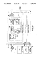
- FIG. 7 is a block diagram showing an embodiment of the present invention.
- FIGS. 8(a)-8(e)-and 9(a)-9(e) are timing charts for explaining the operation of the embodiment of FIG. 7;
- FIG. 10 is a block diagram for explaining the detailed operation of a synchronizing signal generating circuit in the embodiment of FIG. 7;
- FIG. 11 is a block diagram of a major part of another embodiment of the present invention.
- FIG. 12 shows the entire arrangement of the embodiment of FIG. 11.
- FIGS. 13(a)-13(j) are timing charts for explaining the operation of the embodiment of FIG. 11.
- FIG. 7 there is shown a block diagram of an embodiment of the present invention, which comprises digital trunk cards 20, 21 and 22 as trunk circuits.
- Each of the digital trunk cards 20, 21 and 22 includes a clock extracting circuit 24 and a receiver 25 for receiving a signal from an associated digital line (the details of only the digital trunk card 20 being shown).
- the clock extracting circuit 24 includes an clock extracter 240 for extracting a clock signal CK from the digital line, a frame bit extracting circuit 241 for extracting a frame bit and after extraction, for generating an output of high level "H", a frequency dividing circuit 242 for generating an extraction clock signal CK8 of 8 KHz on the basis of an output signal of the clock extracter 240, a flip-flop (D-FF) 243 for causing the transmission of the "H" level output of the frame bit extracting circuit 241 in response to a synchronizing signal SYNC and for stopping the output of the frequency dividing circuit 242 when it is impossible to extract a frame bit, an AND gate 244, and a buffer 245 for driving an 8KHz extraction clock line 26 on an open drain basis.
- D-FF flip-flop
- a clock generating circuit 27 receives the clock signal CK8 from the 8 KHz extraction clock line 26 and for generating a clock signal CKSW on the basis of the received clock signal CK8 and sending it to a time switch (TSW) 28 for time-divisional exchanging operation through a PLL circuit and so on in the time switch in such a manner that a data on the digital line is synchronized with the operation of the time switch 28 of the exchange.
- the time switch 28 exchanges the PCM data shown in FIG. 3 on a time divisional basis on the PCM highway (PCM bus).
- the clock generating circut 27 is included in the time switch 109 and more specifically, a part including the clock generating circuit 27 and the time switch 28 in FIG. 7 corresponds to the time switch 109 in FIG. 3.
- a synchronizing signal generating circuit 29 receives the clock signal CK8 from the 8 KHz extraction clock line 26 and generates the synchronizing signal SYNC for establishing synchronization in operation between the digital trunk cards 20, 21 and 22.
- FIGS. 8 and 9 are timing charts for explaining the operation of the embodiment of FIG. 7, in which FIG. 8 is for explaining the operation of a digital trunk card inserted in (plugged in) in the course of the operation and FIG. 9 is for explaining the operation of the digital trunk card plugged out in the course of the operation. Explanation will be made as to the operation of the arrangement of FIG. 7 by referring to FIGS. 8 and 9.
- the frame bit extracting circuit 241 extracts a frame (framing) bit from the signal on the associated digital line.
- the framing bit will now be explained.
- data for 24 channels are multiplexed and transmitted at a transmission rate of 64Kbps per channel.
- This means that data are transmitted at a transmission rate of 192 bits ( 24 channels ⁇ 8 bits) per frame or per 125 ⁇ s.
- the data are merely continuously chained in the form of a series of data thus it is impossible to find the head part of data corresponding to one frame.
- one framing bit is attached to the head part of one frame for identification between frames.
- the invention is arranged to output the clock signal CK8.
- the frame bit extracting circuit 241 is arranged to generate an output signal of high (H) level and apply it to a D input terminal of the D-FF 243, whereby the D-FF 243 is put in a synchronizing signal (SYNC) awaiting condition.
- H high
- SYNC synchronizing signal
- the synchronizing signal SYNC becomes active, then the D-FF 243 is set.
- the synchronizing signal is such a negative logic pulse as shown in FIG. 8(a) or FIG. 9(a) which is used to reset the frequency dividing circuit 242.
- the reason for it is as follows. In the event where many digital trunk cards are incoporated in the exchange, the phase of the clock signal CK8 of the clock extraction circuit 24 in each of the trunk cards varies from card to card. To avoid this, the frequency dividing circuits 242 of the respective cards are reset by the common synchronizing signal to thereby synchronize the clock signals CK8 of the respective cards.
- the frequency dividing circuits 242 may by reset at the time of turning the card ON, but after the turning ON it must be reset for another trunk card plugged in.
- the synchronizing signal SYNC is generated at the synchronizing signal generating circuit 29 and supplied to the frequency dividing circuit 242 at intervals of constant time to reset the frequency divider 242.
- the AND gate 244 passes the output of the frequency divider 242 therethrough and sends it to the open-drain buffer 245 to apply +5 V to the 8 KHz extraction clock line 26.
- the frequency divider 242 are reset by the synchronizing signal SYNC. Accordingly, even when another digital trunk card is already inserted (even when the clock CK8 is already transmitted to the 8 KHz extraction clock line 26), the synchronizing signal is superimposed and thus the plug-in of a trunk card can be realized without affecting the signal on the 8 KHz extraction clock line 26.
- the already plugged-in trunk cards cause the continuous output of the 8 KHz extraction clock CK as shown by a timing chart of FIG. 9.
- the plug-out of the trunk card or cards can be carried out while not affecting the 8 KHz extraction clock CK8 and the 8 KHz extraction clock signal CK8 can be output for attaining synchronization between the digital lines and the exchange until the last trunk card removed.
- the frequency divider 242 of the clock extracting circuit 24 divides the output of the clock extracter 240 with respect to frequency to generate a division output having a frequency of 8 KHz, that is, equal to the sampling rate of the digital line and to establish synchronization between the exchange and the line.
- a division output having a frequency of 8 KHz, that is, equal to the sampling rate of the digital line and to establish synchronization between the exchange and the line.
- 193 bits including the aforementioned framing bit are transmitted in a time of 125 ⁇ sec., so that, when such a 193-increment counter that can extract and count up to 193 clock pulses in the time of 125 ⁇ sec. is used, the 8 KHz extraction clock signal CK8 can be easily generated.
- the 8 KHz extraction clock line 26 is connected to the plurality of digital trunks 20 to 22 so that the 8 KHz extraction clock signals CK8 extracted from the respective digital lines are superimposed on the clock line 26.
- the superimposed 8 KHz extraction clock signal CK8 on the clock line 26 has a duty factor not exceeding 50%, since the outputs of the clock extracting circuits 24 of the respective digital trunks become different from each other in phase. Further, the output phase corresponds in maximum to nearly the output pulses of the clock extracting circuit 24 ⁇ one pulse.
- the frequency divider 242 is already reset, the outputs of the frequency dividers 242 of the respective digital trunks become erroneous.
- the reset interval time of the frequency divider 242 is set to be long, a time rate of generating this error can be made sufficiently small and can be regarded substantially negligible.
- the synchronizing signal SYNC is commonly used for the frequency dividers.
- the synchronizing-signal generating circuit 29 for generating the synchronizing signal SYNC is arranged as shown in FIG. 10. That is, a counter 290 counts the 8 KHz signal received from the 8 KHz extraction clock line 26 and sends it to a one-shot pulse generating circuit 291 to generate thereat the synchronizing signal SYNC having a predetermined pulse width.
- the maximum count number of the counter 290 is set so that the period of the synchronizing signal SYNC corresponds to about 1 second.
- the synchronizing signal SYNC is not yet generated so that the clock signal CK8 does not appear on the 8 KHz extraction clock line 26.
- another counter 292 is provided separately from the counter 290 so that the counter 292 counts the clock signal received from an oscillator 293, a one-shot pulse generating circuit generates a pseudo sysnchronizing signal SYNC' as a one-shot pulse of about 1.1 seconds according to the output of the counter 292, the one-shot pulse is applied to an OR gate 295 which also receives the one-shot pulse from the one-shot pulse generator 291, whereby an output of the OR gate 295 is used as the synchronizing signal SYNC.
- the counter 292 is arranged to be cleared by the output of the counter 290.
- the synchronizing signal SYNC is applied to the firstly-inserted digital trunk for a time period of about 1.1 seconds, whereby the 8 KHz extraction clock signal CK8 is output.
- the counter 292 is cleared by the count output of the counter 290 before the counter 292 transmits its count output, so that, for the second and subsequent digital trunks, the 8 KHz extraction clock signal CK8 is output on the basis of the synchronizing signal SYNC generated through the counter 290.
- the extraction clock signals from all the digital trunk cards housed within the exchange are used to establish synchronization with the digital lines and are not applied to faulty one of the lines, and further the extraction clock signals of all the digital trunk cards within the exchange are transmitted through the common transmission line.
- the present embodiment can advantageously avoid the enlargement of the exchange.
- FIG. 11 Shown in FIG. 11 is a major part of another embodiment of the present invention, and more specifically a block diagram of an arrangement of a monitor/control circuit to be attached to each one of the T1 trunks.
- the monitor/control circuit includes, as shown in FIG. 11, flip-flops 801 and 815, an XOR gate (exclusive "OR " gate) 802, resistors 803, 804, 807 and 812, capacitors 805, 808 and 813, one-shot circuits 806 and 811, an inverter 809, a 3-state buffer 810, and an OR gate 814.
- Reference numeral 816 represents an extracted DA1 clock signal.
- the DS1 clock signal 816 is applied as an operational clock to the flip-flop 801 which also receives a frame pulse 407 as a clear signal.
- a Q output of the flip-flop 801 and the the DS1 clock signal 816 are applied to the XOR gate 802 to generate an exclusive "OR" therebetween.
- a circuit constituted of the resistors 803 and 804 and the capacitor 805 corresponds to an integrating circuit.
- the output of the XOR gate 802 is supplied through the integrating circuit to an input terminal A of the one-shot circuit 806 and also through the inverter 809 to an input terminal A of the one-shot circuit 811.
- a circuit of the resistor 807 and capacitor 808 and a circuit of the resistor 812 and capacitor 813 respectively connected to the one-shot circuits 806 and 911 are circuits for determining their time constants, and the one-shot circuits 806 and 811 are trigger type circuits which respectively output a pulse after applied with a trigger but when not applied again with a second trigger before the passage of a time corresponding to the aforementioned time constant.
- the outputs of the one-shot circuits 806 and 811 are supplied through the OR gate 814 to the flip-flop 815 as its clock, which flip-flop 815 in turn applies an output at its invert output terminal Q to the 3-state buffer 810 as its gate control signal.
- the DS1 clock signal 816 is also supplied through the 3-state buffer 810 to the time switch 109.
- the monitor/control circuit having such an arrangement as mentioned above is provided to each of the T1 trunks so that, as shown in FIG. 12, a T1 trunk 800 with the monitor/control circuit supplies its DS1 clock signal 205 to the time switch 109 and also the time switch 109 supplies its frame pulse 407 to each of the T1 trunks 800.
- the DS1 clock signal (refer to FIG. 13(b)) is applied to the clock terminal of the flip-flop 801, while the frame pulse (refer to FIG. 13(a)) from the time switch 109 is applied to the clear terminal of the flip-flop 801.
- the output (refer to FIG. 13(c)) at the output terminal Q of the flip-flop 801 as well as the DS1 clock signal 816 (refer to FIG. 13(b)) are supplied to the XOR gate 802 to find an exclusive "OR” and to thereby detect a phase difference between the frame pulse and the DS1 clock signal.
- the output (refer to FIG.
- the XOR gate 802 coresponding to the phase difference is sent through the aforementioned integrating circuit (including the resistors 803 and 804 and the capacitor 805) to the one-shot circuit 806.
- the integrating circuit is provided to eliminate noise components (spikes) from the output of the XOR gate 802.
- the output of the XOR gate 802 subjected to the noise elimination through the integrating circuit is applied to the one-shot circuit 806 (see FIG. 13(e)). More in detail, the output of the XOR gate 802 is applied to an input terminal A of the one-shot circuit 806 the time constant of which is determined the resistor 812 and the capacitor 808.
- the one-shot circuit 806 changes its output from low level to high (see FIG. 13 (f)).
- the duty factor of the pulse applied to the input terminal A of the one-shot circuit 806 varies with the period and becomes longer, as shown in FIG. 13(e).
- the time constant of the one-shot circuit 806 is set so that the circuit 806 generates the output not at a time point T1 but at a time point T2 (>T1).
- the output of the one-shot circuit 806 causes the flip-flop 815 as a DA1 extracting circuit to be inverted so that the buffer 810 is opened and the DS1 clock signal is sent to the time switch 109.
- the duty factor of the pulse at the input terminal A of the one-shot circuit 806 sometimes become short.
- the output of the one-shot circuit 811 receiving as its input a signal (see FIG. 13(g)) corresponding to an inversion of the input of the one-shot circuit 806 becomes long.
- the output see FIG.
- the outputs of the one-shot circuits 811 and 806 can be used to detect whether or not synchronization with the time switch 109 is established. Even when the synchronization is not attained, the output of the OR gate 814 is applied to the DS1 extracting circuit (flip-flop) 815 to drive the same (see FIG. 13(j)) to open the 3-state gate buffer 810, whereby the DS1 clock signal extracted form the T1 trunk in question can be transmitted.
- the function of issuing the DS1 extraction clock signal is provided to each of the T1 trunks, so that a phase difference between the frame pulse issued from the time switch and the own extracted clock is found, and when the phase difference exceeds a predetermined constant value, the exchange judges to be out of frequency synchronization and the own T1 trunk sends the DS1 clock signal to the time switch. Therefore, even when one of the plurality of T1 trunks which supplied to the DS1 clock signal to the time switch becomes faulty and stops the supply of the DS1 clock signal thereto, the other trunks instead can supply the clock signal and the time switch can synchronized and continuously operated.
Landscapes
- Engineering & Computer Science (AREA)
- Computer Networks & Wireless Communication (AREA)
- Signal Processing (AREA)
- Use Of Switch Circuits For Exchanges And Methods Of Control Of Multiplex Exchanges (AREA)
Applications Claiming Priority (4)
| Application Number | Priority Date | Filing Date | Title |
|---|---|---|---|
| JP63-324866 | 1988-12-22 | ||
| JP32486688A JPH02170699A (ja) | 1988-12-22 | 1988-12-22 | ディジタル交換機 |
| JP543089A JPH02185139A (ja) | 1989-01-12 | 1989-01-12 | 構内交換機 |
| JP1-5430 | 1989-01-12 |
Publications (1)
| Publication Number | Publication Date |
|---|---|
| US5099474A true US5099474A (en) | 1992-03-24 |
Family
ID=26339374
Family Applications (1)
| Application Number | Title | Priority Date | Filing Date |
|---|---|---|---|
| US07/454,597 Expired - Lifetime US5099474A (en) | 1988-12-22 | 1989-12-21 | Digital exchange and its control method |
Country Status (3)
| Country | Link |
|---|---|
| US (1) | US5099474A (fr) |
| CA (1) | CA2006452C (fr) |
| GB (1) | GB2227626B (fr) |
Cited By (1)
| Publication number | Priority date | Publication date | Assignee | Title |
|---|---|---|---|---|
| US5521903A (en) * | 1993-12-27 | 1996-05-28 | At&T Corp. | Port system for interfacing digital PBX to digital transmission facility |
Families Citing this family (1)
| Publication number | Priority date | Publication date | Assignee | Title |
|---|---|---|---|---|
| DE19623480C1 (de) * | 1996-06-12 | 1997-10-30 | Siemens Ag | Verfahren zur Generierung eines zur Steuerung einer Datenausgabe verwendbaren Ausgabetaktsignals in Abhängigkeit von einem von mehreren Eingabetaktsignalen |
Citations (8)
| Publication number | Priority date | Publication date | Assignee | Title |
|---|---|---|---|---|
| US3863033A (en) * | 1973-04-30 | 1975-01-28 | Gte Automatic Electric Lab Inc | Step-by-step telephone central exchanges for use with pcm communication networks |
| US4332026A (en) * | 1980-03-07 | 1982-05-25 | Ibm Corporation | Multiple data rate digital switch for a TDMA communications controller |
| US4339815A (en) * | 1979-05-04 | 1982-07-13 | Compagnie Industrielle Des Telecommunications Cit-Alcatel | Multiplex connection unit for use in a time-division exchange |
| US4499575A (en) * | 1981-09-18 | 1985-02-12 | Compagnie Industrielle Des Telecommunications Cit-Alcatel | Group of terminal units for a digital exchange |
| US4546469A (en) * | 1982-12-06 | 1985-10-08 | Compagnie Industrielle Des Telecommunications Cit-Alcatel | System for processing channel signalling in a time-division digital exchange |
| US4633460A (en) * | 1983-03-31 | 1986-12-30 | Hitachi, Ltd. | Time division switching system |
| US4698801A (en) * | 1983-12-29 | 1987-10-06 | Fujitsu Limited | Digital exchange system |
| JPH0220943A (ja) * | 1989-05-18 | 1990-01-24 | Kenwood Corp | 角度変調回路 |
-
1989
- 1989-12-21 US US07/454,597 patent/US5099474A/en not_active Expired - Lifetime
- 1989-12-21 CA CA002006452A patent/CA2006452C/fr not_active Expired - Lifetime
- 1989-12-21 GB GB8928870A patent/GB2227626B/en not_active Expired - Lifetime
Patent Citations (8)
| Publication number | Priority date | Publication date | Assignee | Title |
|---|---|---|---|---|
| US3863033A (en) * | 1973-04-30 | 1975-01-28 | Gte Automatic Electric Lab Inc | Step-by-step telephone central exchanges for use with pcm communication networks |
| US4339815A (en) * | 1979-05-04 | 1982-07-13 | Compagnie Industrielle Des Telecommunications Cit-Alcatel | Multiplex connection unit for use in a time-division exchange |
| US4332026A (en) * | 1980-03-07 | 1982-05-25 | Ibm Corporation | Multiple data rate digital switch for a TDMA communications controller |
| US4499575A (en) * | 1981-09-18 | 1985-02-12 | Compagnie Industrielle Des Telecommunications Cit-Alcatel | Group of terminal units for a digital exchange |
| US4546469A (en) * | 1982-12-06 | 1985-10-08 | Compagnie Industrielle Des Telecommunications Cit-Alcatel | System for processing channel signalling in a time-division digital exchange |
| US4633460A (en) * | 1983-03-31 | 1986-12-30 | Hitachi, Ltd. | Time division switching system |
| US4698801A (en) * | 1983-12-29 | 1987-10-06 | Fujitsu Limited | Digital exchange system |
| JPH0220943A (ja) * | 1989-05-18 | 1990-01-24 | Kenwood Corp | 角度変調回路 |
Cited By (1)
| Publication number | Priority date | Publication date | Assignee | Title |
|---|---|---|---|---|
| US5521903A (en) * | 1993-12-27 | 1996-05-28 | At&T Corp. | Port system for interfacing digital PBX to digital transmission facility |
Also Published As
| Publication number | Publication date |
|---|---|
| CA2006452C (fr) | 1996-06-18 |
| GB2227626A (en) | 1990-08-01 |
| CA2006452A1 (fr) | 1990-06-22 |
| GB8928870D0 (en) | 1990-02-28 |
| GB2227626B (en) | 1993-11-17 |
Similar Documents
| Publication | Publication Date | Title |
|---|---|---|
| US4920535A (en) | Demultiplexer system | |
| HU219747B (hu) | Eljárás szinkronizálásra | |
| JPS585619B2 (ja) | 時分割多重デ−タ伝送装置 | |
| US6256326B1 (en) | Pseudo-synchronization prevention method in SDH transmission mode, pseudo-synchronization preventing SDH transmission system, and transmitter-receiver in pseudo-synchronization preventing SDH transmission system | |
| GB2220327A (en) | Telephone exchange synchronized with digital network | |
| US4631721A (en) | Bidirectional communication system of a two-wire bus comprising an active terminator | |
| US4247936A (en) | Digital communications system with automatic frame synchronization and detector circuitry | |
| US4730302A (en) | Monitoring means for digital signal multiplex equipment | |
| EP0589117B1 (fr) | Adapteur pour raccorder un réseau de transmission du type "clear-channel" | |
| US5099474A (en) | Digital exchange and its control method | |
| US4987591A (en) | Electronic telephone apparatus able to supply sync clock signals reliably, and method of controlling the supply of sync clock signals | |
| US4010325A (en) | Framing circuit for digital signals using evenly spaced alternating framing bits | |
| US5208840A (en) | Method and arrangement for detecting framing bit sequence in digital data communications system | |
| AU639731B2 (en) | A flywheel circuit | |
| US5506843A (en) | Subscriber group digital transmitter | |
| US5003560A (en) | Receiving counter phase synchronization circuit of the synchronous transmission system | |
| DE3586963T2 (de) | Schaltung fuer teilnehmerleitungssignalisierung in einem vermittlungssystem. | |
| US4847836A (en) | Circuit arrangement for synchronizing the units in the switching exchanges and repeaters of a time-division multiplex transmission system | |
| SU1043713A1 (ru) | Устройство дл передачи дискретной информации | |
| JPH02185139A (ja) | 構内交換機 | |
| JPH04371096A (ja) | 位相同期検出方式 | |
| JPH0425743B2 (fr) | ||
| JP3385832B2 (ja) | 接点情報伝送インタフェース部 | |
| KR920002884B1 (ko) | T1 전송선로의 신호 처리회로 | |
| GB1140685A (en) | Improved retiming system for asynchronous pulse code trains |
Legal Events
| Date | Code | Title | Description |
|---|---|---|---|
| AS | Assignment |
Owner name: KABUSHIKI KAISHA TOSHIBA, A CORP. OF JAPAN, JAPAN Free format text: ASSIGNMENT OF ASSIGNORS INTEREST.;ASSIGNORS:OHTSUKA, EIJI;IKEMORI, KIMIO;REEL/FRAME:005279/0350 Effective date: 19900205 |
|
| STCF | Information on status: patent grant |
Free format text: PATENTED CASE |
|
| CC | Certificate of correction | ||
| FEPP | Fee payment procedure |
Free format text: PAYOR NUMBER ASSIGNED (ORIGINAL EVENT CODE: ASPN); ENTITY STATUS OF PATENT OWNER: LARGE ENTITY |
|
| FPAY | Fee payment |
Year of fee payment: 4 |
|
| FPAY | Fee payment |
Year of fee payment: 8 |
|
| FPAY | Fee payment |
Year of fee payment: 12 |