US5105651A - Method of and apparatus for analyzing exhaust gases of motor vehicles - Google Patents
Method of and apparatus for analyzing exhaust gases of motor vehicles Download PDFInfo
- Publication number
- US5105651A US5105651A US07/554,297 US55429790A US5105651A US 5105651 A US5105651 A US 5105651A US 55429790 A US55429790 A US 55429790A US 5105651 A US5105651 A US 5105651A
- Authority
- US
- United States
- Prior art keywords
- signals
- exhaust gases
- catalytic converter
- computer
- downstream
- Prior art date
- Legal status (The legal status is an assumption and is not a legal conclusion. Google has not performed a legal analysis and makes no representation as to the accuracy of the status listed.)
- Expired - Fee Related
Links
Images
Classifications
-
- F—MECHANICAL ENGINEERING; LIGHTING; HEATING; WEAPONS; BLASTING
- F01—MACHINES OR ENGINES IN GENERAL; ENGINE PLANTS IN GENERAL; STEAM ENGINES
- F01N—GAS-FLOW SILENCERS OR EXHAUST APPARATUS FOR MACHINES OR ENGINES IN GENERAL; GAS-FLOW SILENCERS OR EXHAUST APPARATUS FOR INTERNAL-COMBUSTION ENGINES
- F01N11/00—Monitoring or diagnostic devices for exhaust-gas treatment apparatus
-
- G—PHYSICS
- G01—MEASURING; TESTING
- G01M—TESTING STATIC OR DYNAMIC BALANCE OF MACHINES OR STRUCTURES; TESTING OF STRUCTURES OR APPARATUS, NOT OTHERWISE PROVIDED FOR
- G01M15/00—Testing of engines
- G01M15/04—Testing internal-combustion engines
- G01M15/10—Testing internal-combustion engines by monitoring exhaust gases or combustion flame
- G01M15/102—Testing internal-combustion engines by monitoring exhaust gases or combustion flame by monitoring exhaust gases
- G01M15/104—Testing internal-combustion engines by monitoring exhaust gases or combustion flame by monitoring exhaust gases using oxygen or lambda-sensors
-
- G—PHYSICS
- G01—MEASURING; TESTING
- G01M—TESTING STATIC OR DYNAMIC BALANCE OF MACHINES OR STRUCTURES; TESTING OF STRUCTURES OR APPARATUS, NOT OTHERWISE PROVIDED FOR
- G01M17/00—Testing of vehicles
- G01M17/007—Wheeled or endless-tracked vehicles
-
- F—MECHANICAL ENGINEERING; LIGHTING; HEATING; WEAPONS; BLASTING
- F01—MACHINES OR ENGINES IN GENERAL; ENGINE PLANTS IN GENERAL; STEAM ENGINES
- F01N—GAS-FLOW SILENCERS OR EXHAUST APPARATUS FOR MACHINES OR ENGINES IN GENERAL; GAS-FLOW SILENCERS OR EXHAUST APPARATUS FOR INTERNAL-COMBUSTION ENGINES
- F01N2550/00—Monitoring or diagnosing the deterioration of exhaust systems
- F01N2550/02—Catalytic activity of catalytic converters
-
- F—MECHANICAL ENGINEERING; LIGHTING; HEATING; WEAPONS; BLASTING
- F02—COMBUSTION ENGINES; HOT-GAS OR COMBUSTION-PRODUCT ENGINE PLANTS
- F02B—INTERNAL-COMBUSTION PISTON ENGINES; COMBUSTION ENGINES IN GENERAL
- F02B1/00—Engines characterised by fuel-air mixture compression
- F02B1/02—Engines characterised by fuel-air mixture compression with positive ignition
- F02B1/04—Engines characterised by fuel-air mixture compression with positive ignition with fuel-air mixture admission into cylinder
-
- Y—GENERAL TAGGING OF NEW TECHNOLOGICAL DEVELOPMENTS; GENERAL TAGGING OF CROSS-SECTIONAL TECHNOLOGIES SPANNING OVER SEVERAL SECTIONS OF THE IPC; TECHNICAL SUBJECTS COVERED BY FORMER USPC CROSS-REFERENCE ART COLLECTIONS [XRACs] AND DIGESTS
- Y02—TECHNOLOGIES OR APPLICATIONS FOR MITIGATION OR ADAPTATION AGAINST CLIMATE CHANGE
- Y02A—TECHNOLOGIES FOR ADAPTATION TO CLIMATE CHANGE
- Y02A50/00—TECHNOLOGIES FOR ADAPTATION TO CLIMATE CHANGE in human health protection, e.g. against extreme weather
- Y02A50/20—Air quality improvement or preservation, e.g. vehicle emission control or emission reduction by using catalytic converters
-
- Y—GENERAL TAGGING OF NEW TECHNOLOGICAL DEVELOPMENTS; GENERAL TAGGING OF CROSS-SECTIONAL TECHNOLOGIES SPANNING OVER SEVERAL SECTIONS OF THE IPC; TECHNICAL SUBJECTS COVERED BY FORMER USPC CROSS-REFERENCE ART COLLECTIONS [XRACs] AND DIGESTS
- Y02—TECHNOLOGIES OR APPLICATIONS FOR MITIGATION OR ADAPTATION AGAINST CLIMATE CHANGE
- Y02T—CLIMATE CHANGE MITIGATION TECHNOLOGIES RELATED TO TRANSPORTATION
- Y02T10/00—Road transport of goods or passengers
- Y02T10/10—Internal combustion engine [ICE] based vehicles
- Y02T10/12—Improving ICE efficiencies
-
- Y—GENERAL TAGGING OF NEW TECHNOLOGICAL DEVELOPMENTS; GENERAL TAGGING OF CROSS-SECTIONAL TECHNOLOGIES SPANNING OVER SEVERAL SECTIONS OF THE IPC; TECHNICAL SUBJECTS COVERED BY FORMER USPC CROSS-REFERENCE ART COLLECTIONS [XRACs] AND DIGESTS
- Y02—TECHNOLOGIES OR APPLICATIONS FOR MITIGATION OR ADAPTATION AGAINST CLIMATE CHANGE
- Y02T—CLIMATE CHANGE MITIGATION TECHNOLOGIES RELATED TO TRANSPORTATION
- Y02T10/00—Road transport of goods or passengers
- Y02T10/10—Internal combustion engine [ICE] based vehicles
- Y02T10/40—Engine management systems
Definitions
- the invention relates to motor vehicles in general, and more particularly to improvements in methods of and in apparatus for analyzing and evaluating exhaust gases of motor vehicles. Still more particularly, the invention relates to improvements in methods of and in apparatus for analyzing and evaluating exhaust gases of motor vehicles wherein the exhaust pipe contains a three-way catalytic converter downstream of a lambda sensor.
- U.S. Pat. No. 4,782,690 to Terasaka discloses an air/fuel ratio detecting apparatus and a method of detecting an abnormal condition of the apparatus.
- U.S. Pat. No. 4,441,359 to Ezoe discloses a method of and an apparatus for testing vehicles.
- the apparatus employs an exhaust gas tester which samples gases at the discharge end of the exhaust pipe and transmits signals to a central control device employing a programmable microcomputer.
- East German Pat. No. 269 673 to Heinze et al. discloses an apparatus for and a method of testing oxidative catalytic converters.
- An object of the invention is to provide a method of analyzing and evaluating exhaust gases which can be practiced while a vehicle is at a standstill or in motion so that it is not necessary to employ a test stand.
- Another object of the invention is to provide a method which can be practiced by resorting, at least in part, to available instruments and other pieces of equipment.
- a further object of the invention is to provide a simple, compact and inexpensive apparatus for the practice of the above outlined method.
- An additional object of the invention is to provide an apparatus which can employ certain standard components of motor vehicles.
- Still another object of the invention is to provide an apparatus which can be carried by a vehicle during testing of the vehicle and which renders it possible to test one and the same vehicle during standstill or while the wheels of the vehicle are in motion on a road rather than on a test stand.
- One feature of the present invention resides in the provision of a method of analyzing and evaluating exhaust gases which issue from the exhaust pipe of a motor vehicle wherein the exhaust gases pass through an adjustable three-way catalytic converter which is installed downstream of a lambda sensor.
- the improved method comprises the steps of memorizing first signals which are transmitted by the sensor during at least one stage of operation of the vehicle (e.g., while the vehicle is at a standstill and is idling or while the vehicle is in motion of the road), sampling the exhaust gases in the exhaust pipe downstream of the catalytic converter and generating second signals which denote certain parameters of sampled exhaust gases, storing reference signals which denote the desired parameters of exhaust gases for a vehicle type corresponding to that of the tested vehicle, and comparing the stored reference signals with the first signals and/or with the second signals.
- the memorizing step can be carried out while the vehicle is in motion, and the signals from the lambda sensor can be memorized for a period of at least two minutes, particularly for a period of two to four minutes.
- the sampling step can comprise ascertaining the CO and HC contents of exhaust gases downstream of the catalytic converter and transmitting the corresponding second signals to a computer which stores the reference signals.
- the comparing step follows the step of transmitting the second signals.
- the method can further comprise the step of displaying information which denotes the differences between stored reference signals and the first and/or second signals when such differences are ascertained in the course of the comparing step.
- the information can be displayed visibly and/or audibly, e.g., on a screen, by printing the information on a sheet or web of paper or another carrier of information, or otherwise.
- the reference signals can be stored in a computer which receives first signals from the lambda sensor and second signals after elapse of first and second intervals following the starting of a cold engine.
- Such method can further comprise the steps of measuring the first and second intervals, transmitting to the computer additional information denoting the measured intervals, and processing the additional signals with the first and second signals.
- the at least one stage can involve idling the engine at approximately 1000 RPM, and the method can further comprise the steps of memorizing, sampling and comparing while the engine is operated under no-load conditions at approximately 3000 RPM, and utilizing the results of the two comparing steps for determination of the efficiency and/or condition of the catalytic converter.
- Another feature of the invention resides in the provision of an apparatus for evaluating exhaust gases which issue from the exhaust pipe of a motor vehicle wherein the exhaust pipe contains an adjustable three-way catalytic converter downstream of a lambda sensor which transmits first signals denoting, for example, the oxygen content of exhaust gases.
- the apparatus comprises a memory having input means for first signals, means for sampling exhaust gases downstream of the catalytic converter and for transmitting second signals denoting predetermined parameters of exhaust gases, and means for storing reference signals denoting the desired parameters of exhaust gases.
- the storing means has input means for the first and second signals, and such storing means is operative to compare the reference signals with the first and second signals.
- the parameters which are sampled by the sampling means can include the CO content and the HC content of exhaust gases.
- the memory can be a portable memory having at least one output and being designed to be installed in or to be carried by the motor vehicle during testing.
- the storing means can comprise a stationary computer, and the apparatus can further comprise means for separably connecting the at least one output of the portable memory with the respective input means of the computer.
- the memory can form part of the storing means, and the storing means can comprise a portable computer which is designed to be installed in or to be carried by the motor vehicle during evaluation of exhaust gases.
- the apparatus can comprise means for establishing a direct electrical connection between the storing means and the sampling means.
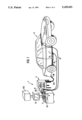
- FIG. 1 is a perspective view of a motor vehicle with the engine idling and with an apparatus which embodies one form of the invention in the process of analyzing exhaust gases issuing from the exhaust pipe which contains a three-way catalytic converter downstream of a lambda sensor; and
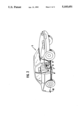
- FIG. 2 is a perspective view of a second vehicle and of a modified apparatus wherein the output of the lambda sensor is directly connected with a computer on the passenger seat of the motor vehicle.
- an apparatus 1 which can be used to carry out an analysis and an evaluation of exhaust gases issuing from the exhaust pipe 10 of a motor vehicle 5.
- the engine of the vehicle 5 is on and is idling, i.e., the vehicle is at a standstill.
- the apparatus 1 comprises a computer 2 which has a memory for storage of reference signals denoting the desired parameters of exhaust gases issuing from the exhaust pipe of a particular motor vehicle, e.g., a sedan of U.S., German, Japanese or other make.
- the computer 2 has one or more inputs which are separably connected with one or more outputs of a discrete memory 3 for temporary storage of (first) signals supplied by a conventional lambda sensor 7 which is installed in the exhaust pipe 10 upstream of an adjustable three-way catalytic converter 6 and is connected with the memory 3 by a cable 8 or any other suitable conductor.
- the computer 2 is further connected to a grounded part of the motor vehicle 5 (by a conductor 9) and is separably connected with an output of a sampling instrument or detector 4.
- the detector 4 includes a hose 4a which is shown as being inserted into the outlet of the exhaust pipe 10.
- the detector 4 can be of any standard design and serves to ascertain the CO and HC contents of exhaust gases downstream of the catalytic converter 6.
- the reference character 3a denotes a conductor which separably connects an output of the memory 3 with an input of the computer 2.
- the memory 3 is sufficiently small to find room in the passenger compartment, in the trunk or elsewhere in the motor vehicle 5.
- the entire computer is designed as a portable unit which can be confined in the passenger compartment, in the trunk or elsewhere in the motor vehicle 5.
- signals which are transmitted by the sensor 7 can be memorized for a selected interval of time (e.g., 2 to 4 minutes) while the vehicle 5 is at a standstill or while the vehicle is in motion.
- a complete test can be carried out in the following way:
- the cold engine of the vehicle 5 is started and the vehicle remains at a standstill (i.e., the engine is idling) in the course of a first stage or cycle of a complete multi-stage testing operation.
- the next stage involves analyzing the exhaust gases (particularly the NO content as determined by the sensor 7) while the vehicle is in motion on a road (i.e., the wheels of the vehicle need not be caused to rotate on the rollers of a test stand) and while the engine is under load.
- the next (e.g., last) stage of testing is carried out while the engine is hot and is idling.
- the conductor 8 is put to use to connect the output of the lambda sensor 7 with the memory 3 of FIG. 1 or with the corresponding input of the computer 2 of FIG. 2, and the conductor 9 is put to use to connect the computer 2 with a grounded part of the vehicle 5.
- the hose 4a of the detector 4 is connected to the discharge end of the exhaust pipe 10, i.e., the hose 4a receives exhaust gases downstream of the catalytic converter 6.
- the engine of the motor vehicle 5 is assumed to be cold; then the cold engine is started, the detector 4 samples the exhaust gases and registers the CO and HC contents downstream of the catalytic converter 6.
- the conductor 8 transmits to a counter or timer of the memory 3 and/or computer 2 an additional signal denoting the interval of time which elapses from the instant of starting the engine to the instant when the sensor 7 is set in operation.
- the computer 2 receives an additional signal which denotes the length of the interval of time elapsing from the instant of starting the cold engine and the instant when the catalytic converter 6 is set in operation.
- Such additional signals are processed with signals which are transmitted by the sensor 7 and detector 4. The latter transmits to the computer 2 (second) signals which denote the CO and HC contents of exhaust gases at the discharge end of the exhaust pipe 10.
- the apparatus of FIG. 1 can be simplified if the connection 11 between the detector 4 and the computer 2 is omitted and the person in charge reads the information which is displayed by the detector 4 to transmit such information to the computer 2 by way of a keyboard 2a.
- the computer 2 is connected with a unit 12 which displays the results of measurements, particularly deviations (if any) of first signals (from the sensor 7) and/or second signals (from the detector 4) from reference signals which are stored in the memory of the computer and denote the desired parameters of exhaust gases issuing from the exhaust pipe of the particular (tested) motor vehicle 5.
- the unit 12 can serve to display data which are furnished by the sensor 7 and/or detector 4.
- the illustrated display unit 12 can be replaced by or used in conjunction with a printer 112 which furnishes a printed record of information pertaining to data supplied by the sensor 7 and/or detector 4 and/or the information which is furnished by the computer 2 and denotes deviations of signals generated by the sensor 7 and/or detector 4 from corresponding reference signals in the memory of the computer 2.
- the person in charge can immediately proceed with the next stage which involves analyzing and evaluating exhaust gases while the vehicle 5 is in motion under load.
- the memory 3, or the memory 3 and the computer 2, or only the computer 2 (if the memory 3 is embodied in the computer) is placed into the passenger compartment of or is otherwise accommodated in the motor vehicle 5 so that the vehicle can be driven on a selected road.
- the computer 2 (which is assumed to embody a memory replacing the memory 3 of FIG. 1) is connected (by conductor 8) with the sensor 7 and the computer is also connected with a grounded part of the vehicle 5 (via conductor 9).
- the discharge end of the exhaust pipe 10 is disconnected from the hose 4a of the detector 4. Signals which are transmitted by the sensor 7 via conductor 8 are stored in the memory (3) of the computer 2 while the vehicle 5 is in motion. As a rule, the vehicle 5 will be driven in accordance with a preselected pattern; for example, the vehicle will be caused to travel at a preselected speed for a predetermined interval of time. This second stage of testing can also involve coasting of the vehicle.
- the next testing stage involves idling of the hot engine and connection of the hose 4a to the discharge end of the exhaust pipe 10.
- the computer 2 then receives signals from the detector 4 and, at the same time, receives signals from the memory 3 or from its own memory (if the memory 3 is embodied in the computer).
- the third stage is carried out while the engine is heated up but is idling so that the hose 4a of the detector 4 can be connected to the discharge end of the exhaust pipe 10.
- the computer 2 evaluates the signals which are transmitted to its inputs during the three testing stages, and such evaluation can involve (and often involves) a comparison of signals from the sensor 7 and detector 4 with reference signals which are stored in the computer and denote the desired parameters of exhaust gases of the tested vehicle 5.
- the memory of the computer 2 can store a number of sets of reference signals, one set for each of a series of different motor vehicles 5, so that one and the same computer can be used for effective testing of exhaust gases of numerous types and makes of motor vehicles.
- the reference signals or data which are stored in the memory of the computer 2 can be of the type known as Typ-Pruf US FTP 75-values and/or US FTP 75 US 83/87 values.
- the results of the evaluating operation can be displayed by the unit 12 and/or recorded by the printer 112.
- the test can be carried out indoors or outdoors at temperatures between 10° C. and 30° C. Thus, it is normally not necessary to heat or cool the indoor testing facility which entails substantial savings in energy.
- a multi-stage test can be completed within a period of 10 to 15 minutes, i.e., the engine can be tested while it is cold, while the vehicle is in motion under load and while the engine is hot and idling, and the three stages of such test can be completed in not more than 15 minutes.
- the computer 2 can be used as a means for ascertaining the efficiency of the catalytic converter 6 with a very high degree of accuracy. Experiments indicate that the accuracy of the efficiency test has an error factor of not more than ⁇ 5 percent. The reason is that the computer 2 can process data which are obtained as a result of testing under a large number of different circumstances including testing after a cold start, testing while the engine is under load, testing while the hot engine is idling, and so on.
- the conductor 8 can be readily affixed to a lambda sensor which is already installed in the exhaust pipe of a motor vehicle to transmit signals to the memory 3 or directly to the computer 2 if the latter embodies the memory 3 or an equivalent thereof. This does not necessitate any complex manipulations of the conductor for the lambda sensor and/or a separation of an existing conductor which transmits signals from the lambda sensor.
- the signals which are transmitted by the computer 2 can be utilized to determine the rate of aging or the actual efficiency of the catalytic converter 6. This can be accomplished in the following way: The engine is started and is caused to idle at say 1000 RPM. During such idling, the person in charge carries out a test with the detector and simultaneously with the lambda sensor 7. The measurements are repeated while the engine is idling (no-load conditions) at a higher rotational speed to increase the exhaust gas output. For example, a second test can be carried out while the RPM of the idling engine is between approximately 2500 and 3000. The computer 2 processes the thus obtained data and calculates the efficiency of the catalytic converter 6. If there is no appreciable difference between the ascertained efficiencies following the first and second tests, this warrants the conclusion that the operation of the catalytic converter as well as of the engine is satisfactory.
- the computer 2 or another component is used to ascertain the actual efficiency on the basis of characteristic data for the engine which are stored in the computer and are normally or invariably ascertained on the basis of measurements under load. This results in determination of an additional reduction of the efficiency of the converter (in comparison with the measured reduction of efficiency at, for example, 3000 RPM) which corresponds to the actual efficiency during operation under load.
- the improved apparatus 1 can be used to ascertain, while the motor vehicle is at a standstill, whether or not the operation of the catalytic converter is still satisfactory.
- the catalyst is still satisfactory after a certain period of use, e.g., while the odometer reading has risen by 100000 kilometers.
- the computer 2 can be used to ascertain the extent to which the conversion rate (i.e., the effectiveness of the converter) has decreased as a result of aging.
- the testing with the apparatus 1 can also serve to ascertain whether or not the tuning of the engine is satisfactory. For example, if the difference between the efficiencies at, for example, 1000 and 3000 RPM exceeds a certain range, this could be attributed to improper tuning or adjustment of the engine. In fact, if the difference between the efficiencies at two different rotational speeds exceeds a given range, the computer 2 can be utilized to analyze the engine and to indicate the defects, if any. For example, the CO content upstream of the catalytic converter 6 can be too high or too low, the regulation in response to signals from the sensor 7 can be unsatisfactory, and so forth. Once the computer 2 has detected the presence of a defect, the person in charge is much more likely to ascertain the exact nature of the defect with very little loss in time. The test or tests can be repeated when the repair work upon the engine is completed in order to ascertain whether or not the repairman has actually eliminated that defect which has caused the apparatus 1 to furnish readings denoting one or more defects in the engine.
- Lambda sensors and adjustable three-way catalytic converters are standard parts of many types of motor vehicles. Reference may be had, for example, to pages 261 to 269 of the Mobil Car Service Manual, 1982 Edition. Furthermore, lambda sensors are described in published German patent application No. 34 43 649 of Abthoff et al. which refers, among others, to an article by Glockler entitled "Advances in closed-loop lambda-controlled fuel injection systems meant to meet most stringent emission levels" (Proc. Int. Symposium on Automotive Technology and Automation, ISATA 81, Swiss, Sept. 7 to 11, 1981, Volume 1, pages 308-326, published by Automotive Automation Ltd., Croydon, England). Reference may also be had to published German patent application No. 36 34 873 of Inamoto et al.
- the senor 7 and the catalytic converter 6 constitute standard components of many motor vehicles, it is merely necessary to employ a conventional detector 4 (which is available in all or practically all repair shops and similar establishments) so that the overall cost of the improved apparatus 1 is sufficiently low to permit its utilization not only by large organizations but also by medium sized and small as well as very small establishments.
- An expensive component of many presently known exhaust gas evaluating and analyzing apparatus, namely a test stand, is not needed for the practice of the improved method.
Landscapes
- Engineering & Computer Science (AREA)
- Chemical & Material Sciences (AREA)
- Combustion & Propulsion (AREA)
- General Physics & Mathematics (AREA)
- Physics & Mathematics (AREA)
- Emergency Medicine (AREA)
- Health & Medical Sciences (AREA)
- Chemical Kinetics & Catalysis (AREA)
- Mechanical Engineering (AREA)
- General Engineering & Computer Science (AREA)
- Testing Of Engines (AREA)
- Exhaust Gas After Treatment (AREA)
- Sampling And Sample Adjustment (AREA)
- Measuring Oxygen Concentration In Cells (AREA)
- Investigating Or Analyzing Materials By The Use Of Electric Means (AREA)
Applications Claiming Priority (2)
| Application Number | Priority Date | Filing Date | Title |
|---|---|---|---|
| DE3923737 | 1989-07-18 | ||
| DE3923737A DE3923737C2 (de) | 1989-07-18 | 1989-07-18 | Verfahren zum Messen von Abgaswerten bei Kraftfahrzeugen mit geregeltem Drei-Wege-Katalysator und Lambdasonde |
Publications (1)
| Publication Number | Publication Date |
|---|---|
| US5105651A true US5105651A (en) | 1992-04-21 |
Family
ID=6385288
Family Applications (1)
| Application Number | Title | Priority Date | Filing Date |
|---|---|---|---|
| US07/554,297 Expired - Fee Related US5105651A (en) | 1989-07-18 | 1990-07-17 | Method of and apparatus for analyzing exhaust gases of motor vehicles |
Country Status (7)
| Country | Link |
|---|---|
| US (1) | US5105651A (fr) |
| EP (1) | EP0409013B1 (fr) |
| JP (1) | JPH03115963A (fr) |
| AT (1) | ATE96907T1 (fr) |
| DE (3) | DE3923737C2 (fr) |
| DK (1) | DK0409013T3 (fr) |
| ES (1) | ES2046604T3 (fr) |
Cited By (33)
| Publication number | Priority date | Publication date | Assignee | Title |
|---|---|---|---|---|
| US5175997A (en) * | 1991-12-12 | 1993-01-05 | Blanke Sr John D | Method of determining catalytic converter efficiency on computer controlled vehicles |
| US5259189A (en) * | 1990-12-11 | 1993-11-09 | Abb Patent Gmbh | Method and apparatus for monitoring a catalytic converter |
| US5550737A (en) * | 1993-11-05 | 1996-08-27 | Environmental Systems Products, Inc. | Method for analysis of vehicle performance characteristics |
| US5572424A (en) * | 1994-05-23 | 1996-11-05 | Automotive Information Systems | Diagnostic system for an engine employing collection of exhaust gases |
| US5639957A (en) * | 1995-10-12 | 1997-06-17 | Snap-On Technologies, Inc. | Method and apparatus for performing modal mass analysis of exhaust gas from motor vehicle |
| GB2310044A (en) * | 1996-02-09 | 1997-08-13 | Sun Electric Uk Ltd | Analysing catalyst and other systems operations |
| US5711021A (en) * | 1995-08-07 | 1998-01-20 | Snap-On Technologies, Inc. | Method for graphically displaying vehicle test data |
| US5898107A (en) * | 1996-09-07 | 1999-04-27 | Robert Bosch Gmbh | Method and arrangement for monitoring the operation of a hydrocarbon sensor for an internal combustion engine |
| WO1999035480A1 (fr) * | 1998-01-05 | 1999-07-15 | U.S. Environmental Protection Agency | Debitmetre modulaire et en temps reel pour les gaz d'echappement d'un vehicule en mouvement et systeme fournissant des informations sur les emissions |
| US5993743A (en) * | 1997-03-26 | 1999-11-30 | Spx Corporation | Hand-held vehicle exhaust analyzer |
| US6000218A (en) * | 1994-11-22 | 1999-12-14 | Heraeus Electro-Nite International N.V. | System for monitoring the functioning ability of catalytic converters and/or lambda sensors |
| US6470732B1 (en) | 1998-01-05 | 2002-10-29 | The United States Of America As Represented By The Administrator Of The National Aeronautics And Space Administration | Real-time exhaust gas modular flowmeter and emissions reporting system for mobile apparatus |
| US6560545B2 (en) | 1999-12-29 | 2003-05-06 | Enviromental Systems Products, Inc. | System and method for remote analysis of small engine vehicle emissions |
| US20030120434A1 (en) * | 1998-12-11 | 2003-06-26 | Didomenico John | Exhaust opacity measuring device |
| US20030210848A1 (en) * | 2001-09-27 | 2003-11-13 | Mark Troll | "optical switch controlled by selective activation and deactivation of an optical source" |
| US6721649B2 (en) | 2000-11-20 | 2004-04-13 | Oasis Emission Consultants Inc. | Engine emission analyzer |
| US6723989B1 (en) | 1998-09-17 | 2004-04-20 | Envirotest Systems Corporation | Remote emissions sensing system and method with a composite beam of IR and UV radiation that is not split for detection |
| US20040168504A1 (en) * | 2000-07-26 | 2004-09-02 | Sensors Inc. | Vehicle ultraviolet gas emission analysis |
| US20050043868A1 (en) * | 2003-07-09 | 2005-02-24 | Mitcham Arvon L. | Vehicle on-board reporting system for state emissions test |
| US6983639B1 (en) | 1998-09-17 | 2006-01-10 | Environmental Systems Products Holdings Inc. | Remote emissions sensing system with improved NOx detection |
| US20060064255A1 (en) * | 1999-01-12 | 2006-03-23 | James Johnson | Remote vehicle emission sensing device with single detector |
| US20060150713A1 (en) * | 2002-10-23 | 2006-07-13 | Brown Clive A | Test device for internal combustion engine |
| US7164132B2 (en) | 1998-10-30 | 2007-01-16 | Envirotest Systems Corp. | Multilane remote sensing device |
| US20070205752A1 (en) * | 2006-02-17 | 2007-09-06 | Leigh Dwayne L | Portable Electronics Testing Device |
| USRE40767E1 (en) | 1996-10-26 | 2009-06-23 | Environmental Systems Products Holdings Inc. | Unmanned integrated optical remote emissions sensor (RES) for motor vehicles |
| US20100024521A1 (en) * | 2008-07-31 | 2010-02-04 | ARKTIK GmbH | Automatic Determination of an Emission Value for a Motor Vehicle |
| US20100089138A1 (en) * | 2008-10-09 | 2010-04-15 | Gm Global Technology Operations, Inc. | Portable Emissions Measurement Adapter Device |
| US20120239308A1 (en) * | 2011-03-16 | 2012-09-20 | Global Mrv, Inc. | Emissions measuring system |
| US8495908B2 (en) * | 2011-09-21 | 2013-07-30 | GM Global Technology Operations LLC | Method and system for simulating various engine operating conditions to evaluate engine emissions test equipment |
| USRE44976E1 (en) | 1996-09-26 | 2014-07-01 | Envirotest Systems Holdings Corp. | Speed and acceleration monitoring device using visible laser beams |
| US20150253300A1 (en) * | 2012-09-20 | 2015-09-10 | C.R.D. Centro Ricerche Ducati Trento S.R.L. | System and method for monitoring atmospheric pollution |
| US11274625B2 (en) | 2020-02-11 | 2022-03-15 | Ford Global Technologies, Llc | Method of controlling a vehicle assembly |
| CN114236053A (zh) * | 2021-12-16 | 2022-03-25 | 北京华志信科技股份有限公司 | 一种车辆尾气一体化综合监管方法 |
Families Citing this family (10)
| Publication number | Priority date | Publication date | Assignee | Title |
|---|---|---|---|---|
| DE4213807C2 (de) * | 1992-04-27 | 2001-06-28 | Deutz Ag | Verfahren zur Erfassung von Betriebsgrößen einer Brennkraftmaschine |
| US5524433A (en) * | 1994-12-27 | 1996-06-11 | Ford Motor Company | Methods and apparatus for monitoring the performance of hydrocarbon engine emission trapping devices |
| EP0880022A3 (fr) * | 1997-05-20 | 1999-02-24 | Sensors, Inc. | Mesurage de l'émission de la masse en effluent gazeux d'une véhicule |
| DE19753006C2 (de) * | 1997-11-30 | 2001-01-18 | Wwu Wissenschaftliche Werkstat | Verfahren zur Beurteilung von Abgasgrenzwertverletzungen und zur Beurteilung der Güte abgasrelevanter Bauteile bei niedrig emittierenden Kraftfahrzeugen während der Fahrt |
| US6085582A (en) * | 1998-04-29 | 2000-07-11 | Sensors, Inc. | Vehicle mass emission measurement |
| JP2000314684A (ja) | 1999-04-16 | 2000-11-14 | Sensors Inc | 車両用質量排出量測定 |
| RU2297611C2 (ru) * | 2005-06-08 | 2007-04-20 | Новосибирский государственный аграрный университет | Способ определения токсичных компонентов и дымности отработавших газов, прорывающихся через герметизирующие уплотнения соединений двигателя внутреннего сгорания в рабочую зону, и устройство для его осуществления |
| WO2008136360A1 (fr) * | 2007-04-27 | 2008-11-13 | Horiba, Ltd. | Analyseur de gaz d'échappement |
| JP5520359B2 (ja) * | 2011-11-10 | 2014-06-11 | 株式会社堀場製作所 | 排ガス分析システム及び当該システム用プログラム |
| CN115128221B (zh) * | 2022-09-02 | 2022-11-18 | 运易通科技有限公司 | 一种远程运输设备的碳排放连续式检测装置及其检测方法 |
Citations (22)
| Publication number | Priority date | Publication date | Assignee | Title |
|---|---|---|---|---|
| DE2304464A1 (de) * | 1973-01-31 | 1974-08-08 | Bosch Gmbh Robert | Messfuehler fuer die ueberwachung der funktionsfaehigkeit von katalysatoren in abgasentgiftungsanlagen von brennkraftmaschinen |
| US3917454A (en) * | 1974-07-22 | 1975-11-04 | Sun Electric Corp | Exhaust emission analysis method |
| US3969932A (en) * | 1974-09-17 | 1976-07-20 | Robert Bosch G.M.B.H. | Method and apparatus for monitoring the activity of catalytic reactors |
| DE2643739A1 (de) * | 1976-09-29 | 1978-03-30 | Bosch Gmbh Robert | Verfahren zur ueberwachung der aktivitaet von katalysatoren fuer die abgasreinigung |
| DE2752862A1 (de) * | 1977-11-26 | 1979-05-31 | Porsche Ag | Verfahren zur ueberpruefung der abgasemission einer brennkraftmaschine |
| DE2951316A1 (de) * | 1979-12-20 | 1981-07-02 | Degussa Ag, 6000 Frankfurt | Katalytisches filter fuer die dieselabgasreinigung |
| DE3144349A1 (de) * | 1981-11-07 | 1983-05-19 | Bayerische Motoren Werke AG, 8000 München | Diesel-brennkraftmaschine mit russabbrenn-vorrichtung |
| EP0096514A2 (fr) * | 1982-06-05 | 1983-12-21 | Bl Technology Limited | Détection des constituants combustibles ou carburants dans les gaz d'échappement d'un moteur à explosion |
| DE3232416A1 (de) * | 1982-09-01 | 1984-03-01 | Kienzle Apparate Gmbh, 7730 Villingen-Schwenningen | Datenerfassungssystem fuer fahrzeuge |
| US4441359A (en) * | 1981-03-04 | 1984-04-10 | Nissan Motor Company, Limited | Method and apparatus for inspecting vehicles |
| DE3438172A1 (de) * | 1984-10-18 | 1986-04-24 | Marte Electronic, Götzis | Vorrichtung zur erfassung und bewertung der abgase von abgas-emittierenden anordnungen |
| DE3443649A1 (de) * | 1984-11-30 | 1986-06-05 | Daimler-Benz Ag, 7000 Stuttgart | Verfahren zur ueberpruefung der katalysatorfunktion bei einem mit (lambda)-sonden-regelung ausgeruesteten kraftfahrzeug-otto-motor |
| DE3516981A1 (de) * | 1985-05-10 | 1986-11-13 | Audi AG, 8070 Ingolstadt | Verfahren zum ueberpruefen der funktionsfaehigkeit eines abgaskatalysators |
| DE3534033A1 (de) * | 1985-09-24 | 1987-04-02 | Chassiotis Periklis G | Verfahren zum bestimmen der schadstoffemission und des kraftstoffverbrauchs eines otto-motors |
| DE3634873A1 (de) * | 1985-10-21 | 1987-04-23 | Honda Motor Co Ltd | Verfahren zum bestimmen der eignung eines abgaskonzentrationssensors |
| US4691562A (en) * | 1985-07-30 | 1987-09-08 | Daimler-Benz Aktiengesellschaft | Process for determining aging condition of exhaust-gas catalyst |
| EP0239744A2 (fr) * | 1986-02-18 | 1987-10-07 | Siemens Aktiengesellschaft | Procédé pour tenir propre les conduits de mesure d'appareils pour mesurer l'émission, application du procédé et sonde de prise de gaz pour son exécution |
| DE3736259A1 (de) * | 1986-11-07 | 1988-07-28 | Volkswagen Ag | Einrichtung zur ermittlung des konvertierungsgrads eines katalysators |
| DE3809082A1 (de) * | 1987-03-30 | 1988-10-13 | Volkswagen Ag | Verfahren zur zumindest annaehernd zeitgleichen analyse mehrerer gasproben |
| US4782690A (en) * | 1985-07-17 | 1988-11-08 | Nissan Motor Co., Ltd. | Air/fuel ratio detecting apparatus, and method of detecting normal and abnormal conditions of the sensor |
| DD269673A1 (de) * | 1987-12-29 | 1989-07-05 | Technische Universitaet "Otto Von Guericke" Magdeburg,Dd | Verfahren und anordnung zur ueberpruefung der funktionsfaehigkeit von oxidationskatalysatoren |
| US5041265A (en) * | 1989-07-12 | 1991-08-20 | Horiba, Ltd. | Hydrogen gas analyzer with improved delivery system |
-
1989
- 1989-07-18 DE DE3923737A patent/DE3923737C2/de not_active Expired - Fee Related
- 1989-07-18 DE DE8915832U patent/DE8915832U1/de not_active Expired - Lifetime
-
1990
- 1990-07-06 ES ES199090112925T patent/ES2046604T3/es not_active Expired - Lifetime
- 1990-07-06 EP EP90112925A patent/EP0409013B1/fr not_active Expired - Lifetime
- 1990-07-06 DK DK90112925.4T patent/DK0409013T3/da active
- 1990-07-06 DE DE90112925T patent/DE59003305D1/de not_active Expired - Fee Related
- 1990-07-06 AT AT90112925T patent/ATE96907T1/de not_active IP Right Cessation
- 1990-07-17 US US07/554,297 patent/US5105651A/en not_active Expired - Fee Related
- 1990-07-18 JP JP2188158A patent/JPH03115963A/ja active Pending
Patent Citations (22)
| Publication number | Priority date | Publication date | Assignee | Title |
|---|---|---|---|---|
| DE2304464A1 (de) * | 1973-01-31 | 1974-08-08 | Bosch Gmbh Robert | Messfuehler fuer die ueberwachung der funktionsfaehigkeit von katalysatoren in abgasentgiftungsanlagen von brennkraftmaschinen |
| US3917454A (en) * | 1974-07-22 | 1975-11-04 | Sun Electric Corp | Exhaust emission analysis method |
| US3969932A (en) * | 1974-09-17 | 1976-07-20 | Robert Bosch G.M.B.H. | Method and apparatus for monitoring the activity of catalytic reactors |
| DE2643739A1 (de) * | 1976-09-29 | 1978-03-30 | Bosch Gmbh Robert | Verfahren zur ueberwachung der aktivitaet von katalysatoren fuer die abgasreinigung |
| DE2752862A1 (de) * | 1977-11-26 | 1979-05-31 | Porsche Ag | Verfahren zur ueberpruefung der abgasemission einer brennkraftmaschine |
| DE2951316A1 (de) * | 1979-12-20 | 1981-07-02 | Degussa Ag, 6000 Frankfurt | Katalytisches filter fuer die dieselabgasreinigung |
| US4441359A (en) * | 1981-03-04 | 1984-04-10 | Nissan Motor Company, Limited | Method and apparatus for inspecting vehicles |
| DE3144349A1 (de) * | 1981-11-07 | 1983-05-19 | Bayerische Motoren Werke AG, 8000 München | Diesel-brennkraftmaschine mit russabbrenn-vorrichtung |
| EP0096514A2 (fr) * | 1982-06-05 | 1983-12-21 | Bl Technology Limited | Détection des constituants combustibles ou carburants dans les gaz d'échappement d'un moteur à explosion |
| DE3232416A1 (de) * | 1982-09-01 | 1984-03-01 | Kienzle Apparate Gmbh, 7730 Villingen-Schwenningen | Datenerfassungssystem fuer fahrzeuge |
| DE3438172A1 (de) * | 1984-10-18 | 1986-04-24 | Marte Electronic, Götzis | Vorrichtung zur erfassung und bewertung der abgase von abgas-emittierenden anordnungen |
| DE3443649A1 (de) * | 1984-11-30 | 1986-06-05 | Daimler-Benz Ag, 7000 Stuttgart | Verfahren zur ueberpruefung der katalysatorfunktion bei einem mit (lambda)-sonden-regelung ausgeruesteten kraftfahrzeug-otto-motor |
| DE3516981A1 (de) * | 1985-05-10 | 1986-11-13 | Audi AG, 8070 Ingolstadt | Verfahren zum ueberpruefen der funktionsfaehigkeit eines abgaskatalysators |
| US4782690A (en) * | 1985-07-17 | 1988-11-08 | Nissan Motor Co., Ltd. | Air/fuel ratio detecting apparatus, and method of detecting normal and abnormal conditions of the sensor |
| US4691562A (en) * | 1985-07-30 | 1987-09-08 | Daimler-Benz Aktiengesellschaft | Process for determining aging condition of exhaust-gas catalyst |
| DE3534033A1 (de) * | 1985-09-24 | 1987-04-02 | Chassiotis Periklis G | Verfahren zum bestimmen der schadstoffemission und des kraftstoffverbrauchs eines otto-motors |
| DE3634873A1 (de) * | 1985-10-21 | 1987-04-23 | Honda Motor Co Ltd | Verfahren zum bestimmen der eignung eines abgaskonzentrationssensors |
| EP0239744A2 (fr) * | 1986-02-18 | 1987-10-07 | Siemens Aktiengesellschaft | Procédé pour tenir propre les conduits de mesure d'appareils pour mesurer l'émission, application du procédé et sonde de prise de gaz pour son exécution |
| DE3736259A1 (de) * | 1986-11-07 | 1988-07-28 | Volkswagen Ag | Einrichtung zur ermittlung des konvertierungsgrads eines katalysators |
| DE3809082A1 (de) * | 1987-03-30 | 1988-10-13 | Volkswagen Ag | Verfahren zur zumindest annaehernd zeitgleichen analyse mehrerer gasproben |
| DD269673A1 (de) * | 1987-12-29 | 1989-07-05 | Technische Universitaet "Otto Von Guericke" Magdeburg,Dd | Verfahren und anordnung zur ueberpruefung der funktionsfaehigkeit von oxidationskatalysatoren |
| US5041265A (en) * | 1989-07-12 | 1991-08-20 | Horiba, Ltd. | Hydrogen gas analyzer with improved delivery system |
Non-Patent Citations (4)
| Title |
|---|
| "Messung von Automobilabgasen bei Strassenfahrten", Dieter Schurmann and Joachim Staab, Motortechnische Zeitschrift 48 (1987), pp. 35-39. |
| Car Service Manual (1982 Edition), Mobil Oil Corp., pp. 261 269. * |
| Car Service Manual (1982 Edition), Mobil Oil Corp., pp. 261-269. |
| Messung von Automobilabgasen bei Strassenfahrten , Dieter Sch rmann and Joachim Staab, Motortechnische Zeitschrift 48 (1987), pp. 35 39. * |
Cited By (47)
| Publication number | Priority date | Publication date | Assignee | Title |
|---|---|---|---|---|
| US5259189A (en) * | 1990-12-11 | 1993-11-09 | Abb Patent Gmbh | Method and apparatus for monitoring a catalytic converter |
| US5175997A (en) * | 1991-12-12 | 1993-01-05 | Blanke Sr John D | Method of determining catalytic converter efficiency on computer controlled vehicles |
| US5550737A (en) * | 1993-11-05 | 1996-08-27 | Environmental Systems Products, Inc. | Method for analysis of vehicle performance characteristics |
| US5572424A (en) * | 1994-05-23 | 1996-11-05 | Automotive Information Systems | Diagnostic system for an engine employing collection of exhaust gases |
| US6000218A (en) * | 1994-11-22 | 1999-12-14 | Heraeus Electro-Nite International N.V. | System for monitoring the functioning ability of catalytic converters and/or lambda sensors |
| US5711021A (en) * | 1995-08-07 | 1998-01-20 | Snap-On Technologies, Inc. | Method for graphically displaying vehicle test data |
| US5639957A (en) * | 1995-10-12 | 1997-06-17 | Snap-On Technologies, Inc. | Method and apparatus for performing modal mass analysis of exhaust gas from motor vehicle |
| GB2310044A (en) * | 1996-02-09 | 1997-08-13 | Sun Electric Uk Ltd | Analysing catalyst and other systems operations |
| GB2310044B (en) * | 1996-02-09 | 2000-05-24 | Sun Electric Uk Ltd | Analysing catalyst and other systems operations |
| US5898107A (en) * | 1996-09-07 | 1999-04-27 | Robert Bosch Gmbh | Method and arrangement for monitoring the operation of a hydrocarbon sensor for an internal combustion engine |
| USRE44976E1 (en) | 1996-09-26 | 2014-07-01 | Envirotest Systems Holdings Corp. | Speed and acceleration monitoring device using visible laser beams |
| USRE44214E1 (en) | 1996-10-26 | 2013-05-14 | Envirotest Systems Holdings Corp. | Unmanned integrated optical remote emissions sensor (RES) for motor vehicles |
| USRE40767E1 (en) | 1996-10-26 | 2009-06-23 | Environmental Systems Products Holdings Inc. | Unmanned integrated optical remote emissions sensor (RES) for motor vehicles |
| US5993743A (en) * | 1997-03-26 | 1999-11-30 | Spx Corporation | Hand-held vehicle exhaust analyzer |
| US6287519B1 (en) | 1997-03-26 | 2001-09-11 | Spx Corporation | Hand-held vehicle exhaust analyzer |
| US6148656A (en) * | 1998-01-05 | 2000-11-21 | The United States Of America As Represented By The Adminstrator Of The Environmental Protection Agency. | Real-time on-road vehicle exhaust gas modular flowmeter and emissions reporting system |
| AU746060B2 (en) * | 1998-01-05 | 2002-04-11 | U.S. Environmental Protection Agency | Real-time on-road vehicle exhaust gas modular flowmeter and emissions reporting system |
| US6382014B1 (en) | 1998-01-05 | 2002-05-07 | The United States Of America As Represented By The Adminstrator Of The U.S. Environmental Protection Agency | Real-time on-road vehicle exhaust gas modular flowmeter and emissions reporting system |
| US6470732B1 (en) | 1998-01-05 | 2002-10-29 | The United States Of America As Represented By The Administrator Of The National Aeronautics And Space Administration | Real-time exhaust gas modular flowmeter and emissions reporting system for mobile apparatus |
| WO1999035480A1 (fr) * | 1998-01-05 | 1999-07-15 | U.S. Environmental Protection Agency | Debitmetre modulaire et en temps reel pour les gaz d'echappement d'un vehicule en mouvement et systeme fournissant des informations sur les emissions |
| RU2224233C2 (ru) * | 1998-01-05 | 2004-02-20 | Ю.Эс. Энвайрнментал Протекшн Эйдженси | Мобильная система регистрации выхлопных газов автомобиля и расходомерный модуль для нее |
| US6723989B1 (en) | 1998-09-17 | 2004-04-20 | Envirotest Systems Corporation | Remote emissions sensing system and method with a composite beam of IR and UV radiation that is not split for detection |
| US6983639B1 (en) | 1998-09-17 | 2006-01-10 | Environmental Systems Products Holdings Inc. | Remote emissions sensing system with improved NOx detection |
| US7164132B2 (en) | 1998-10-30 | 2007-01-16 | Envirotest Systems Corp. | Multilane remote sensing device |
| US20030120434A1 (en) * | 1998-12-11 | 2003-06-26 | Didomenico John | Exhaust opacity measuring device |
| US20060064255A1 (en) * | 1999-01-12 | 2006-03-23 | James Johnson | Remote vehicle emission sensing device with single detector |
| US7141793B2 (en) | 1999-01-12 | 2006-11-28 | Environmental Systems Products Holdings Inc. | Remove vehicle emission sensing device with single detector |
| US6560545B2 (en) | 1999-12-29 | 2003-05-06 | Enviromental Systems Products, Inc. | System and method for remote analysis of small engine vehicle emissions |
| US20040168504A1 (en) * | 2000-07-26 | 2004-09-02 | Sensors Inc. | Vehicle ultraviolet gas emission analysis |
| US20040159142A1 (en) * | 2000-11-20 | 2004-08-19 | Oasis Emission Consultants Inc. | Engine emission analyzer |
| US6721649B2 (en) | 2000-11-20 | 2004-04-13 | Oasis Emission Consultants Inc. | Engine emission analyzer |
| US20030210848A1 (en) * | 2001-09-27 | 2003-11-13 | Mark Troll | "optical switch controlled by selective activation and deactivation of an optical source" |
| US7665344B2 (en) * | 2002-10-23 | 2010-02-23 | Premier Diagnostics Limited | Test device for internal combustion engine |
| US20060150713A1 (en) * | 2002-10-23 | 2006-07-13 | Brown Clive A | Test device for internal combustion engine |
| US20050043868A1 (en) * | 2003-07-09 | 2005-02-24 | Mitcham Arvon L. | Vehicle on-board reporting system for state emissions test |
| US20070205752A1 (en) * | 2006-02-17 | 2007-09-06 | Leigh Dwayne L | Portable Electronics Testing Device |
| US20100024521A1 (en) * | 2008-07-31 | 2010-02-04 | ARKTIK GmbH | Automatic Determination of an Emission Value for a Motor Vehicle |
| US8047052B2 (en) * | 2008-07-31 | 2011-11-01 | ARKTIK GmbH | Automatic determination of an emission value for a motor vehicle |
| US7946160B2 (en) * | 2008-10-09 | 2011-05-24 | GM Global Technology Operations LLC | Portable emissions measurement adapter device |
| US20100089138A1 (en) * | 2008-10-09 | 2010-04-15 | Gm Global Technology Operations, Inc. | Portable Emissions Measurement Adapter Device |
| US20120239308A1 (en) * | 2011-03-16 | 2012-09-20 | Global Mrv, Inc. | Emissions measuring system |
| US9086342B2 (en) * | 2011-03-16 | 2015-07-21 | Global Mrv, Inc. | Emissions measuring system |
| US8495908B2 (en) * | 2011-09-21 | 2013-07-30 | GM Global Technology Operations LLC | Method and system for simulating various engine operating conditions to evaluate engine emissions test equipment |
| US20150253300A1 (en) * | 2012-09-20 | 2015-09-10 | C.R.D. Centro Ricerche Ducati Trento S.R.L. | System and method for monitoring atmospheric pollution |
| US10006895B2 (en) * | 2012-09-20 | 2018-06-26 | C.R.D. Centro Ricerche Ducati Trento S.R.L. | System and method for monitoring atmospheric pollution |
| US11274625B2 (en) | 2020-02-11 | 2022-03-15 | Ford Global Technologies, Llc | Method of controlling a vehicle assembly |
| CN114236053A (zh) * | 2021-12-16 | 2022-03-25 | 北京华志信科技股份有限公司 | 一种车辆尾气一体化综合监管方法 |
Also Published As
| Publication number | Publication date |
|---|---|
| EP0409013A3 (en) | 1991-10-09 |
| DE8915832U1 (de) | 1991-09-05 |
| ATE96907T1 (de) | 1993-11-15 |
| ES2046604T3 (es) | 1994-02-01 |
| DE59003305D1 (de) | 1993-12-09 |
| EP0409013B1 (fr) | 1993-11-03 |
| DK0409013T3 (da) | 1994-02-28 |
| DE3923737A1 (de) | 1991-01-24 |
| JPH03115963A (ja) | 1991-05-16 |
| EP0409013A2 (fr) | 1991-01-23 |
| DE3923737C2 (de) | 1995-12-14 |
Similar Documents
| Publication | Publication Date | Title |
|---|---|---|
| US5105651A (en) | Method of and apparatus for analyzing exhaust gases of motor vehicles | |
| US3938377A (en) | Method and apparatus for production hot testing of engines under load | |
| US3998095A (en) | Method and apparatus for quickly evaluating engine exhaust gas emissions | |
| US5941918A (en) | Automotive on-board monitoring system for catalytic converter evaluation | |
| US4160373A (en) | Vehicle exhaust gas analysis system with gas blockage interlock | |
| EP1285267B1 (fr) | Appareil et procede d'echantillonnage d'emission | |
| CN108181432B (zh) | 机动车尾气污染物全组分排放测试方法 | |
| US5099680A (en) | Method of analyzing vehicle emissions and in-flight gas analysis apparatus | |
| KR20010033882A (ko) | 실시간 노상 차량 배기 가스 모듈 유량계 및 배출물 보고시스템 | |
| JPH04283644A (ja) | 内燃機関による窒素酸化物の放出をモニタする方法 | |
| US4031747A (en) | Misfire monitor for engine analysis having automatic rescaling | |
| EP0715167B1 (fr) | Appareil pour analyser les caractéristiques d'un détecteur du rapport air/carburant | |
| KR20000035125A (ko) | 내연기관의 배기가스에서 시간 경과에 따른 촉매의 변화와유해물질 배출을 모니터링하고 관찰하는 방법 및 장치 | |
| JPH05209551A (ja) | 車両の電気ヒータの機能能力を検査する方法及び装置 | |
| US5339627A (en) | Method and apparatus for regulating and testing | |
| CA1110087A (fr) | Methode et dispositif pour l'analyse instantanee des gaz d'echappement de moteurs | |
| EP0008199A1 (fr) | Appareil pour déterminer le rendement de la combustion d'un hydrocarbure et méthode et appareil pour l'analyse des defauts des moteurs à combustion interne | |
| US20060218988A1 (en) | Exhaust gas measuring device and method for measuring exhaust gas | |
| Lenaers et al. | The realisation of an on-board emission measuring system serving as a R&D tool for ultra low emitting vehicles | |
| EP0780551B1 (fr) | Méthode pour détecter une baisse de performance d'un catalyseur pour la purification de gaz d'échappement | |
| EP0779416B1 (fr) | Méthode pour détecter une baisse de performance d'un catalyseur pour la purification de gaz d'échappement | |
| Sentoff et al. | Second-by-second characterization of cold-start gas-phase and air toxic emissions from a light-duty vehicle | |
| Schürmann et al. | On-the-road measurements of automotive emissions | |
| Lenaers et al. | Mobile emission measurements for assessing low emitting vehicles exemplified on a CRT-equipped bus | |
| EP3683563B1 (fr) | Système et procédé de surveillance de condensation aqueuse interne d'un tunnel de dilution pour des essais d'émission de véhicule |
Legal Events
| Date | Code | Title | Description |
|---|---|---|---|
| AS | Assignment |
Owner name: GUTMANN MESSTECHNIK AG, SWITZERLAND Free format text: ASSIGNMENT OF ASSIGNORS INTEREST.;ASSIGNOR:GUTMANN, KURT;REEL/FRAME:005412/0157 Effective date: 19900712 |
|
| FEPP | Fee payment procedure |
Free format text: PAYOR NUMBER ASSIGNED (ORIGINAL EVENT CODE: ASPN); ENTITY STATUS OF PATENT OWNER: SMALL ENTITY |
|
| FPAY | Fee payment |
Year of fee payment: 4 |
|
| REMI | Maintenance fee reminder mailed | ||
| LAPS | Lapse for failure to pay maintenance fees | ||
| FP | Lapsed due to failure to pay maintenance fee |
Effective date: 20000421 |
|
| STCH | Information on status: patent discontinuation |
Free format text: PATENT EXPIRED DUE TO NONPAYMENT OF MAINTENANCE FEES UNDER 37 CFR 1.362 |