US5113136A - Gradiometer apparatus with compensation coils for measuring magnetic fields - Google Patents
Gradiometer apparatus with compensation coils for measuring magnetic fields Download PDFInfo
- Publication number
- US5113136A US5113136A US07/468,360 US46836090A US5113136A US 5113136 A US5113136 A US 5113136A US 46836090 A US46836090 A US 46836090A US 5113136 A US5113136 A US 5113136A
- Authority
- US
- United States
- Prior art keywords
- magnetic field
- circuit
- circuits
- field measuring
- magnetic
- Prior art date
- Legal status (The legal status is an assumption and is not a legal conclusion. Google has not performed a legal analysis and makes no representation as to the accuracy of the status listed.)
- Expired - Lifetime
Links
Images




Classifications
-
- G—PHYSICS
- G01—MEASURING; TESTING
- G01R—MEASURING ELECTRIC VARIABLES; MEASURING MAGNETIC VARIABLES
- G01R33/00—Arrangements or instruments for measuring magnetic variables
- G01R33/02—Measuring direction or magnitude of magnetic fields or magnetic flux
- G01R33/025—Compensating stray fields
Definitions
- the present invention relates to an apparatus for measuring a magnetic field, and particularly to an apparatus for eliminating, in measuring a very weak magnetic field, external magnetic noise components generated by other magnetic sources and mixed in with the very weak magnetic field to be measured.
- external magnetic noise causes a problem.
- Sources of the external magnetic noise are geomagnetism, electric cars, elevators, electric appliances such as computers, etc. These sources are located very far, compared to a distance between a pickup coil of the measuring apparatus and a source of the very weak magnetic field to be measured.
- the external magnetic noise may therefore be considered as a uniform magnetic field or uniform gradient field whose direction do not change around the source of the very weak magnetic field.
- the external magnetic noise can be removed by employing, as the pickup coil, a gradiometer such as a first-order gradiometer and a second-order gradiometer.
- a gradiometer such as a first-order gradiometer and a second-order gradiometer.
- This type of pickup coil has, however, manufacturing errors which prevent a complete removal of the noise.
- An object of the present invention is to provide an apparatus for measuring a magnetic field, which surely removes noise caused by a uniform magnetic field as well as remaining noise caused by an imbalance in the gradiometer.
- the gradiometer detects the magnetic field of an object to be measured as well as magnetic noise from an external uniform magnetic field.
- Three compensation coils oriented substantially in different directions detect the magnetic noise in those directions. Magnetic noise components detected by the three compensation coils are weighted and added to each other to find a noise magnetic field existing around the gradiometer. The noise is subtracted from an output of the gradiometer to obtain a correct magnetic field of the object to be measured. In this way, a very weak magnetic field in a human body can be correctly measured.
- FIG. 1A is a schematic view showing an apparatus for measuring a magnetic field with the use of a first-order gradiometer according to the prior art
- FIG. 1B is a schematic view showing an apparatus for measuring a magnetic field employing a second-order gradiometer according to the prior art
- FIG. 2A is a perspective view showing a method of removing noise with the use of a first-order gradiometer and superconducting tabs according to the prior art
- FIG. 2B is a perspective view showing a method of removing noise of a first-order gradiometer by superconducting tabs and compensation loops according to the prior art
- FIG. 3 is a schematic view showing an apparatus for measuring a magnetic field employing three compensation coils according to the prior art
- FIG. 4 is a block diagram showing an apparatus for measuring a magnetic field according to a first aspect of the present invention
- FIGS. 5, 5A and 5B are circuit diagrams showing the details of the respective parts of the apparatus of FIG. 4;
- FIG. 6A is a perspective view showing an arrangement of a second-order gradiometer and compensation coils of the apparatus of FIGS. 4 and 5;
- FIG. 6B is a perspective view showing a way of winding the pickup coil of FIG. 6A;
- FIG. 6C is a perspective view showing a way of winding each compensation coil of FIG. 6A;
- FIG. 7 is a perspective view showing another arrangement of the second-order gradiometer and compensation coils of the apparatus of FIGS. 4 and 5;
- FIG. 8 is a circuit diagram showing the details of a magnetic noise eliminating circuit of FIG. 5;
- FIG. 9 is a circuit diagram showing a magnetic noise eliminating circuit similar to that of FIG. 5 but realized by a digital circuit
- FIG. 10 is a circuit diagram showing a magnetic noise eliminating circuit similar to that of FIG. 5 but realized by a digital circuit and a computer;
- FIG. 11 is a perspective view showing a uniform magnetic field generator of FIG. 10;
- FIGS. 12 and 13 are flowcharts showing control examples of the digital circuit with the computer of FIG. 10;
- FIG. 14 is a block diagram showing an apparatus for measuring a magnetic field according to a second aspect of the invention.
- FIG. 15 is a circuit diagram showing the details of a magnetic noise eliminating circuit of FIG. 14;
- FIG. 16 is a circuit diagram showing a modification of the magnetic noise eliminating circuit of FIG. 14;
- FIG. 17 is a block diagram showing an apparatus for measuring a magnetic field according to the first aspect of the invention, with three gradiometers compensated by one set of compensation coils;
- FIG. 18 is a perspective view showing the details of the compensation coils and second-order gradiometers of FIG. 17;
- FIG. 19 is a block diagram showing an apparatus for measuring a magnetic field according to the second aspect of the invention, with three gradiometers compensated by one set of compensation coils.
- FIGS. 1A to 3 Before describing the preferred embodiments, an explanation will be given of the conventional apparatus for measuring a magnetic field shown in FIGS. 1A to 3.
- a derivative magnetic field detection coil such as a first-order gradiometer 10 shown in FIG. 1A is generally employed.
- a second-order gradiometer 100 shown in FIG. 1B is usually employed.
- various types of derivative pickup coils such as third-order gradiometer (not shown) are employed.
- the pickup coil 10 and an input coil 41b are made of superconducting material to form a superconducting loop, and the input coil 41b is magnetically connected to a highly sensitive magnetic sensor SQUID (super conducting quantum interference device) 41a.
- SQUID super conducting quantum interference device
- a magnetic field H is applied to the pickup coil 10
- a current I flows through the pickup coil 10 and input coil 41b.
- the current I is proportional to magnetic flux ⁇ P intersecting the pickup coil 10, and the current I is oriented to cancel the magnetic flux ⁇ P .
- Magnetic flux ⁇ i from the input coil 41b intersects the SQUID 41a and is detected by the SQUID 41a.
- An output of the SQUID 41a is processed by a SQUID controller 41c, which outputs a signal Vo corresponding to the intersecting magnetic flux.
- the signal Vo is converted by a voltage-current converting circuit 41d into a current proportional to the signal Vo.
- the current flows to a feedback coil 41e magnetically connected with the SQUID 41a, such that magnetic flux is fed back to the SQUID 41a to cancel the magnetic flux ⁇ i input into the SQUID 41a from the input coil 41b.
- the magnetic flux ⁇ i i.e., the magnetic field H is measured, and an output end of the SQUID controller 41c provides a signal proportional to the magnetic field H.
- the portion surrounded by a dotted line in FIGS. 1A and 1B is a magnetic field measuring device 41.
- a first-order gradiometer will be adopted to explain an equivalent coil of the gradiometer coil with respect to a uniform magnetic field.
- the first-order gradiometer comprises two component coils. Supposing the areas of the coils and the unit vectors normal to coil planes are A 1 , 1 and A 2 , 2 , the magnetic flux ⁇ of a uniform magnetic field H intersecting the gradiometer is expressed as follows:
- the scalar product is obtainable by multiplying a product of absolute values of two vectors by a cosine of an angle formed by the two vectors. This may be represented by a sum of products of three components on respective rectangular coordinate axes of the two vectors.
- the areas of the two coil planes shall be equal to each other, and the normal directions of the coil planes shall be correctly opposite to each other.
- the coils involve, however, manufacturing errors, and therefore, the equation (2) is not actually satisfied. Accordingly, the gradiometer provides an output due to the uniform magnetic field.
- the intersecting magnetic flux ⁇ is expressed as follows; ##EQU1##
- the bold type part indicates a vector quantity. Supposing the size of the vector is Ae and its normal direction is ne, the equation (3) is expressed as follows:
- This is equal to magnetic flux produced by a coil intersecting the uniform magnetic field and having an area of Ae and a normal direction of e .
- the gradiometer will be an equivalent of the coil having the area A e and normal direction e .
- the gradiometer is sensitive to the uniform magnetic field.
- the coil will be an equivalent of a coil having a certain area and a certain direction, if the coil has manufacturing errors.
- a manufactured coil has an area A involving an error ratio of about 0.1% or more.
- the parallelism of component coils of the manufactured coil involve errors. Therefore, the coil can reduce external magnetic noise only to about a thousandth.
- FIG. 2A shows a conventional arrangement of three superconducting tabs 12X, 12Y, and 12Z each being a thin plate having a small area (U.S. Pat. No. 3,976,938).
- the tabs are arranged to change a sensitivity in one of three orthogonal axes of a magnetic field. Positions of the tabs are adjusted in the directions of arrow marks X, Y, and Z shown in FIG. 2A to change a distribution of the magnetic field.
- three compensation loops 13X, 13Y, and 13Z are arranged orthogonally to each other (U.S. Pat. Nos. 3,956,690, 3,965,411).
- Superconducting tabs 12X, 12Y, and 12Z are moved to adjust the magnetism blocking quantities of the superconducting tabs with respect to the compensation loops. In both cases, an imbalance of the pickup coil 10 due to manufacturing errors is compensated through the adjustment of the tabs.
- FIG. 3 shows another conventional technique employing three compensation coils 11, 12, and 13. Normals of the planes of the coils are oriented in directions X, Y, and Z to remove noise caused by a uniform magnetic field.
- This technique is disclosed in Japanese Unexamined Patent Publication (Kokai) No. 63-32384.
- numeral 91 denotes a coil for detecting a magnetic field
- 92 an input coil
- 93 a SQUID
- 94 a feedback coil
- 95 a current source
- 96 an output voltage detecting circuit
- 97 variable gain amplifier
- R feedback resistor
- the magnetic noise is cancelled for each of the directions X, Y, and Z. Therefore, to carry out the adjustment correctly in a short time, the normals of the planes of the three compensation coils must correctly be orthogonal to each other, and the externally applied uniform magnetic field must be exactly aligned with each normal to adjust variable resistors. Since errors tend to occur in the directions of the coil planes as well as in the direction of the uniform magnetic field, even repetitive adjustments cannot completely eliminate the noise caused by the uniform magnetic field.
- FIG. 4 is a block diagram showing an embodiment according to the first aspect of the present invention.
- numerals 11, 12, and 13 denote compensation coils. The planes of the coils are set such that the magnetic flux of a uniform magnetic field of optional direction intersects at least one of the coils.
- Numeral 10 denotes a gradiometer.
- Numerals 21, 22, 23, and 20 denote magnetic field measuring circuits for outputting signals proportional to magnetic flux intersecting the compensation coils 11 to 13 and pickup coil 10, respectively.
- Numerals 401, 402, and 403 denote multiplication circuits for amplifying the outputs of the magnetic field measuring circuits 21, 22, and 23, respectively.
- the multiplication circuits 401 to 403 receive weights for changing multiplication factors.
- Numeral 5 denotes an addition and subtraction circuit for subtracting outputs of the multiplication circuits 401 to 403 from an output of the magnetic (or gradiometric) field measuring circuit 20.
- the multiplication circuits 401 to 403 and the addition and subtraction circuit 5 form a magnetic noise eliminating circuit 30.
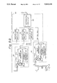
- FIGS. 5, 5A and 5B show the details of the apparatus of FIG. 4 of the invention.
- Each of the magnetic field measuring circuits 21, 22, 23, and 20 comprises an input coil 41b, a SQUID 41a, a feedback coil 41e, a SQUID controller 41c and a voltage-current converting circuit 41d.
- the functions of these elements are the same as those of the conventional circuits shown in FIG. 1A.
- the multiplication circuits 401 to 403 of the magnetic noise eliminating circuit 30 actually comprise variable gain amplifiers 411 to 413 respectively, and the addition and subtraction circuit 5 actually comprises a differential amplifier 50.
- a uniform magnetic field (or uniform gradient magnetic field) is successively applied along axes X, Y, and Z.
- the magnetic field measuring circuits 21, 22, 23, and 20 provide outputs V 1X , V 2X , V 3X and V 0X , respectively.
- the magnetic field measuring circuits 21, 22, 23, and 20 provide outputs V 1Y , V 2Y , V 3Y , and V 0Y respectively.
- the magnetic field measuring circuits 21, 22, 23, and 20 provide outputs V 1Z , V 2Z , V 3Z , and V 0Z , respectively. If the gains of the variable gain amplifiers 411 to 413 are adjusted so that the outputs of the variable gain amplifiers satisfy the following equations (5), the output of the differential amplifier 50 provides a signal from which the noise caused by the uniform magnetic field has been removed: ##EQU2## where b 1 , b 2 , and b 3 are the gains of the variable gain amplifiers 411 to 413, respectively. The gains may be positive and negative values.
- a 1 is a constant determined by an area of the coil 11 and the characteristics of the magnetic field measuring circuit 21; a 2 a constant determined by an area of the coil 12 and the characteristics of the magnetic field measuring circuit 22; and a 3 a constant determined by an area of the coil 13 and a gain of the magnetic field measuring circuit 23.
- the constant a 0 is determined by an effective area of the gradiometer 10 when the intersecting magnetic flux derived from the uniform magnetic field becomes maximum and by a gain of the magnetic field measuring circuit 20 (a 0 will be zero if the gradiometer 10 has no manufacturing error).
- the value between each pair of parentheses is a scalar product.
- the compensation coils 11 to 13 are located farther than the coil 10 from a magnetic source to be measured, so that a magnetic field Hs to be measured reaches the coils 11 to 13 in very small quantity compared to a quantity thereof reaching the coil 10. Therefore, even if the outputs of the magnetic field measuring circuits are substracted from the output of the magnetic (or gradiometric) field measuring circuit 20, an output component of the magnetic field measuring circuit 20 derived from the magnetic field Hs to be measured will remain substantially as it is and will be transferred to the differential amplifier 50.
- a uniform magnetic field is successively applied along three orthogonal axes to find the values b 1 , b 2 , and b 3 . It is not necessary, however, to apply the uniform magnetic field along the three orthogonal axes.
- the uniform magnetic field may be applied in three different directions that are not parallel with any plane. It is supposed that magnetic fields 1 , 2 , and 3 of three directions satisfying the above conditions are successively applied.
- the magnetic field measuring circuits 21 to 23 and 20 provide outputs V 1X , V 2X , V 3X , and V 0X , respectively.
- the magnetic field measuring circuits 21 to 23 and 20 provide outputs V 1Y , V 2Y , V 3Y , and V 0Y , respectively.
- the magnetic field measuring circuits 21 to 23 and 20 provide outputs V 1Z , V 2Z , V 3Z , and V 0Z , respectively.
- the gains of the variable gain amplifiers are adjusted so that the outputs of the variable gain amplifiers satisfy the equations (11).
- the output of the differential amplifier 50 provides a signal from which the noise caused by the uniform magnetic field has been removed.
- FIG. 6A shows a probe 60 for holding the compensation coils 11 to 13 and pickup coil 10 shown in FIGS. 4 and 5.
- the probe 60 comprises a SQUID chip holder 61 for accommodating the magnetic field measuring circuits 20 to 23, a pickup coil supporting material 62 for holding the second-order gradiometer 10, and a compensation coil supporting material 63 for supporting the compensation coils 11 to 13.
- the pickup coil 10 is wound in a manner as shown in FIG. 6B.
- compensation coil chips 64 are disposed on faces X, Y, and Z, respectively.
- the compensation coil chips 64 hold the compensation coils 11 to 13.
- Each of the compensation coils 11 to 13 is a single winding coil as shown in FIG. 6C.
- the compensation coil supporting material 63 is received in an opening 65 formed on the pickup coil supporting material 62.
- Numeral 66 denotes a hole for receiving a rod that protrudes from the bottom of the compensation coil supporting material 63.
- the compensation coil chips 64 supported by the compensation coil supporting material 63 comprise wafers on which the compensation coils 11 to 13 are formed.
- the compensation coil chips 64 are fixed to the three faces X, Y, and Z of a cube.
- the compensation coil supporting material 63 with the fixed coil chips 64 is assembled and embedded in an open block 65 of the pickup coil supporting material 62 to make a SQUID sensor, which is resistant to strain from vibration and aging and demonstrates a high S/N ratio.
- Signals picked up by the pickup coil 10 and compensation coils 11 to 13 are applied to the magnetic field measuring circuits 20 to 23 disposed inside the SQUID chip holder 61 at the upper part of the probe 60.
- the signals are then converted by the circuits 20 to 23 into signals or pulses proportional to the strength of the magnetic field, and output outside.
- FIG. 7 shows another embodiment of the probe 60 for holding the compensation coils 11 to 13 and pickup coil 10.
- numeral 67 denotes a pickup coil bobbin, and 68 a compensation coil holder.
- This embodiment is characterized in that the pickup coil 10 is formed by lithography etching.
- FIG. 8 shows the details of the differential amplifier 50 of the magnetic noise eliminating circuit 30 of FIG. 5.
- the differential amplifier 50 comprises an addition circuit 51 having resistors R 1 to R 4 and an operational amplifier 51a; an addition circuit 52 having resistors R 5 to R 7 and an operational amplifier 52a; and an inverting amplifier 53 having resistors R 8 and R 9 and an operational amplifier 53a.
- the addition circuit 55 adds outputs of the variable gain amplifiers 411 to 413 to each other, and the addition result is inverted and output to the addition circuit 52.
- the inverted addition result is added to the output of the magnetic field measuring circuit 20.
- the outputs of the variable gain amplifiers 411 to 413 are substracted from the output of the magnetic field measuring circuit 20.
- the substracted result is inverted and output to the inverting amplifier 53.
- the inverting amplifier 53 again inverts the substracted result inverted by the addition circuit 52 to return the same to a normal value.
- FIG. 9 shows a digital circuit achieving a function of the magnetic noise eliminating circuit 30 of FIGS. 5A and 5B.
- the magnetic noise eliminating circuit 30 comprises multiplication circuits 421, 422, and 423, an addition and substraction circuit 54, and a timing pulse generator 6.
- the multiplication circuits 421, 422, and 423 comprise sample-hold circuits 421a, 422a, and 423a for helping the normal operation of analog-to-digital converters by sampling and holding analog signal values at an optional time, analog-to-digital converters (hereinafter referred to as A/D converters) 421b, 422b, and 423b, multipliers 421c, 422c, and 423c, and registers 421d, 422d, and 423d.
- A/D converters analog-to-digital converters
- the addition and substraction circuit 54 comprises a sample-hold circuit 54a, an A/D converter 54b, and an adder 54c.
- outputs of the magnetic field measuring circuits 20 to 23 are sampled at certain intervals based on signals from the timing pulse generator 6.
- the sampled outputs are converted into digital signals by the A/D converters 421b, 422b, 423b, and 54b, respectively.
- the values b 1 , b 2 and b 3 are found.
- FIG. 10 shows another embodiment in which a digital circuit realizes a function of the magnetic noise eliminating circuit 30 of FIG. 5B.
- the same parts as those shown in FIG. 9 are represented by like reference numerals.
- the difference between the embodiment of FIG. 10 from that of FIG. 9 will be explained next.
- the noise removing circuit 30 of FIG. 9 processes signals from the magnetic field measuring circuits 20 to 23 by hardware, while the embodiment of FIG. 10 converts signals from the magnetic field measuring circuits 20 to 23 into digital signals and processes the digital signals by software with the use of a processor (a computer) 31. Similar to the embodiment of FIG. 9, an output of the processor 31 is a digital signal, which is therefore converted into an analog signal and output from the magnetic noise eliminating circuit 30.
- the embodiment of FIG. 10 employs a uniform magnetic field generator 8 connected to a timing pulse generator 6 through a sine wave generator 7.
- FIG. 11 shows an arrangement of the uniform magnetic field generator 8 comprising a cylindrically wound coil.
- a uniform magnetic field H to be generated is in parallel with an axis of the cylindrical coil.
- the compensation coils 11 to 13 and pickup coil 10 explained in the previous embodiment are disposed in the center of the cylindrical coil.
- a uniform AC magnetic field is successively applied along the three orthogonal axes X, Y, and Z, and the maximum values V 1X , V 1Y , V 1Z , V 2X , V 2Y , V 2Z , V 3X , V 3Y , V 3Z , V 0X , V 0Y , and V 0Z of AC outputs of the magnetic field measuring circuits 20 to 23 are measured in the respective directions.
- the gain values b 1 , b 2 , and b 3 are calculated, and the values are set in the variable gain amplifiers 411 to 413, thereby providing a signal from which the noise due to the uniform magnetic field has been removed.
- FIGS. 12 and 13 are flowcharts showing the operation of the processor 31 of FIG. 10.
- FIG. 12 shows weighting operation sequences.
- Step 121 an initialization is carried out.
- Step 122 the uniform magnetic field generator 8 applies a uniform magnetic field successively in directions X, Y, and Z.
- Step 123 a trigger signal is applied to the timing pulse generator 6, which then generates a timing pulse.
- the timing pulse is applied to the sample-hold circuits 421a to 423a and 52a as well as to the A/D converters 421b to 423b and 52b.
- Step 124 with the uniform magnetic field in a certain direction, for example in the direction X, digital values converted from the output values V 0X to V 3X of the magnetic field measuring circuits 20 to 23 are fetched by the processor 31.
- Step 125 it is judged whether or not all data for the three directions of the uniform magnetic field have been fetched. If they have not yet been fetched (NO), the Step 122 is repeated. If they have been fetched (YES), Step 126 is carried out.
- the Step 126 based on the fetched digital data for the three directions, the equation (11) is evaluated to find the gain values b 1 , b 2 , and b 3 to be set in the variable gain amplifiers 411 to 413.
- FIG. 13 shows the operation sequences of removing magnetic noise.
- a trigger signal is applied to the timing pulse generator 6, which then generates a timing pulse.
- the timing pulse is input in to the sample-hold circuits 421a to 423a and 52a as well as the A/D converters 421b to 423b and 52b.
- Step 132 digital values converted from output values V 0 to V 3 of the magnetic field measuring circuits 20 to 23 are fetched by the processor 31.
- Step 133 the gain values b 1 , b 2 , and b 3 that have been derived in the Step 126 to be set in the variable gain amplifiers 411 to 413 are used to derive a weighted sum of the output values V 1 to V 3 of the magnetic field measuring circuits 21 to 23.
- the sum is substracted from the output value V 0 of the magnetic field measuring circuit 20, i.e., the noise is removed from the output value V 0 of the magnetic field measuring circuit 20. Accordingly, a signal with no noise is output to the D/A converter 55 in Step 134.
- the D/A converter converts the signal into an analog signal, which is output from the magnetic noise eliminating circuit 30.
- FIG. 14 shows an embodiment according to the second aspect of the invention.
- the magnetic noise eliminating circuit 30 substracts a sum of magnetic noise components from a detected value of a magnetic field of an object to be measured.
- a difference of the embodiment of the second aspect of FIG. 14 is that a magnetic noise eliminating circuit 300 derives a sum of the magnetic noise components and feeds the resultant sum back to a magnetic field measuring circuit for detecting the magnetic field of a measured object.
- the magnetic field measuring circuit is connected with a gradiometer 10 and another feed back coil magnetically connected with the pickup coil 10. According to the fed back sum, the other coil cancels the noise due to the uniform magnetic field intersecting the gradiometer 10.
- FIG. 15 shows the details of the magnetic noise eliminating circuit 300 according to the second aspect of the invention.
- the magnetic noise eliminating circuit 300 comprises variable gain amplifiers 411 to 413 that are the same as those explained before, and an addition and subtraction circuit 56.
- the addition and substraction circuit 56 comprises an addition circuit 51 having, similar to that shown in FIG. 8, resistors R 1 to R 4 and an operational amplifier 51a; a feedback coil 56a magnetically engaging with a superconducting ring having a Josephson junction; a variable resistor 56b acting as current converting means for feeding a current proportional to an output of the addition circuit 51 to the feedback coil 56a; and a switch 56c for preventing a current from flowing from the variable resistor 56b to the feedback coil 56a in finding weight factors.
- the switch 56c is disconnected to open a feedback loop, and the values b 1 , b 2 and b 3 are calculated in the similar manner as in the previous embodiments.
- the values b 1 , b 2 , and b 3 are set as the gains of the variable gain amplifiers 411 to 413, respectively.
- a uniform magnetic field is applied so that an output of the magnetic field measuring circuit 20 reaches a maximum value.
- the switch 56c is connected, and the variable resistor 56b is set to zero the output of the magnetic field measuring circuit 20.
- FIG. 16 shows a modification of the embodiment of FIG. 15.
- the arrangement of this embodiment is similar to that of FIG. 15. Therefore, like parts are represented with like numerals to omit the explanations thereof.
- the difference of the embodiment of FIG. 16 from that of FIG. 15 will be explained next.
- An output of the addition circuit 51 is fed back to a feedback coil 200b magnetically engaging with a SQUID (a superconducting ring) 200a of a magnetic field measuring circuit 200.
- the SQUID 200a includes a Josephson element to cancel magnetic flux from a uniform magnetic field intersecting the SQUID 200a.
- the adjusting operation of this embodiment is the same as that of the embodiment of FIG. 15.
- a switch 56c is disconnected to open a feedback loop, and the values b 1 , b 2 , and b 3 are obtained in a similar manner.
- the values b 1 , b 2 , and b 3 are set the gains of variable gain amplifiers 411 to 413, respectively.
- a uniform magnetic field is applied so that the output of the magnetic field measuring circuit 200 reaches a maximum value.
- the switch 56c is connected, and the variable resistor 56b is set to zero the output of the magnetic field measuring circuit 200.
- Numeral 200c denotes a SQUID controller and 200d a voltage-current converting circuit.
- FIG. 17 shows an embodiment of a multichannel magnetic field measuring apparatus employing the magnetic field measuring apparatuses according to the first aspect of the invention, for simultaneously measuring a magnetic field at n locations.
- This apparatus comprises a set of compensation coils 11, 12, and 13, magnetic field detectors 21, 22, and 23 for detecting a magnetic field through the compensation coils, gradiometers 101 to 10n disposed for respective channels, magnetic field detectors 201 to 20n for detecting a magnetic field through the pickup coils, first variable gain amplifiers 421, 422, and 423 up to "n"th variable gain amplifiers 42(3n-2), 42(3n-1), and 42(3n) for amplifying outputs of the magnetic field detectors 21, 22, and 23 respectively, and differential amplifiers 401 to 40n for substracting a sum of the outputs of the magnetic field detectors 21, 22, and 23 multiplied by weight factors by the variable gain amplifiers 421 to 42(3n) from the outputs of the magnetic field detectors 201 to 20n, channel by channel.
- the magnetic field detector 22 When a uniform magnetic field is applied successively to orthogonal axes X, Y, and Z, the magnetic field detector 22 provides outputs V 1X , V 1Y , and V 1Z the magnetic field detector 22 provides outputs V 2X , V 2Y and V 2Z , the magnetic field detector 23 provides outputs V 3X , V 3Y , and V 3Z and the magnetic field detectors 201 to 20n of the respective channels provides outputs V 201X , V 201Y , and V 201Z to V 20nX , V 20nY , and V 20nZ .
- These outputs are measured, and the gains of the variable gain amplifiers of the respective channels are found and set according to the equations (11), thereby eliminating noise components due to the uniform magnetic field from the outputs of the respective channels.
- FIG. 18 shows an arrangement of probes 60 in the multichannel magnetic field measuring apparatus of FIG. 17. Since only one compensation coil supporting material 63 is necessary, the material 63 is arranged for the central one of n probes 60. The material 63 is the same as that shown in FIG. 6A. The other probes 60 have only cooling holes 66 formed on pickup coil supporting materials.
- FIG. 19 shows an embodiment for measuring a magnetic field at m locations, employing magnetic field detectors according to the second aspect of the invention.
- a set of compensation coils 11, 12, and 13 and a magnetic noise eliminating circuit 301 to 30m operate a sum of magnetic noise components.
- the resultant sum of the magnetic noise components is fed back to coils magnetically engaging with gradiometers 101 to 10m located at m positions respectively to cancel the magnetic noise of a uniform magnetic field intersecting the gradiometers 101 to 10m.
- the magnetic field detectors 20 to 23 of the above embodiments are not necessarily required to be made of superconducting materials.
Landscapes
- Physics & Mathematics (AREA)
- Condensed Matter Physics & Semiconductors (AREA)
- General Physics & Mathematics (AREA)
- Measuring Magnetic Variables (AREA)
- Measurement And Recording Of Electrical Phenomena And Electrical Characteristics Of The Living Body (AREA)
Applications Claiming Priority (4)
| Application Number | Priority Date | Filing Date | Title |
|---|---|---|---|
| JP1-12890 | 1989-01-20 | ||
| JP1012890A JPH02193084A (ja) | 1989-01-20 | 1989-01-20 | 補正コイル内蔵形ピックアップコイル |
| JP1-32824 | 1989-02-14 | ||
| JP3282489A JPH02212788A (ja) | 1989-02-14 | 1989-02-14 | 磁場測定装置 |
Publications (1)
| Publication Number | Publication Date |
|---|---|
| US5113136A true US5113136A (en) | 1992-05-12 |
Family
ID=26348575
Family Applications (1)
| Application Number | Title | Priority Date | Filing Date |
|---|---|---|---|
| US07/468,360 Expired - Lifetime US5113136A (en) | 1989-01-20 | 1990-01-22 | Gradiometer apparatus with compensation coils for measuring magnetic fields |
Country Status (4)
| Country | Link |
|---|---|
| US (1) | US5113136A (fr) |
| EP (1) | EP0379374B1 (fr) |
| CA (1) | CA2008009C (fr) |
| DE (1) | DE69010700T2 (fr) |
Cited By (78)
| Publication number | Priority date | Publication date | Assignee | Title |
|---|---|---|---|---|
| WO1993025274A1 (fr) * | 1992-06-16 | 1993-12-23 | Life Resonances, Inc. | Analyseur de champ magnetique portable destine a detecter les champs magnetiques a resonance d'ions specifiques |
| DE4325059A1 (de) * | 1992-07-24 | 1994-01-27 | Toshiba Kawasaki Kk | Gerät zum Messen von Magnetquellen |
| US5642045A (en) * | 1995-08-18 | 1997-06-24 | International Business Machines Corporation | Magnetic field gradiometer with improved correction circuits |
| US5990679A (en) * | 1997-10-22 | 1999-11-23 | The United States Of America As Represented By The Secretary Of The Navy | Method using corrective factors for determining a magnetic gradient |
| US6008641A (en) * | 1997-10-22 | 1999-12-28 | The United States Of America As Represented By The Secretary Of The Navy | Method using corrective factors for aligning a magnetic gradiometer |
| US6208268B1 (en) | 1993-04-30 | 2001-03-27 | The United States Of America As Represented By The Secretary Of The Navy | Vehicle presence, speed and length detecting system and roadway installed detector therefor |
| US6239596B1 (en) | 1997-06-09 | 2001-05-29 | Joseph J. Stupak, Jr. | Total magnetic flux measuring device |
| US6270686B1 (en) * | 1995-12-27 | 2001-08-07 | Ap One System Co., Ltd. | Method of making a weak-field magnetic field sensor having etched circuit coils |
| WO2004021017A3 (fr) * | 2002-08-28 | 2004-05-06 | Univ Vanderbilt | Procede et dispositif pour l'imagerie haute resolution d'echantillons, reposant sur l'utilisation d'appareils et de procedes de type supraconducteur a interference quantique (squid) |
| US20040263162A1 (en) * | 2003-06-23 | 2004-12-30 | Akihiko Kandori | Magnetic field measurement apparatus |
| US20050088174A1 (en) * | 2001-11-08 | 2005-04-28 | Lee Seung M. | Squid sensor using auxiliary sensor |
| US20050176391A1 (en) * | 2002-04-19 | 2005-08-11 | Butters Bennett M. | System and method for sample detection based on low-frequency spectral components |
| US20070163367A1 (en) * | 2005-12-30 | 2007-07-19 | Sherman Jason T | Magnetic sensor array |
| US20070210790A1 (en) * | 2003-10-09 | 2007-09-13 | Butters Bennette M | System And Method For Characterizing A Sample By Low-Frequency Spectra |
| US20070231872A1 (en) * | 2004-07-27 | 2007-10-04 | Nativis, Inc. | System and Method for Collecting, Storing, Processing, Transmitting and Presenting Very Low Amplitude Signals |
| US20080246472A1 (en) * | 2005-09-07 | 2008-10-09 | Koninklijke Philips Electronics, N.V. | System and Method for Inductively Measuring the Bio-Impedance of a Conductive Tissue |
| US20110254562A1 (en) * | 2008-10-08 | 2011-10-20 | Alstom Technology Ltd | Method and device for detecting short-circuits in the stator core of electric machines |
| US8068648B2 (en) | 2006-12-21 | 2011-11-29 | Depuy Products, Inc. | Method and system for registering a bone of a patient with a computer assisted orthopaedic surgery system |
| WO2013115749A1 (fr) * | 2012-02-02 | 2013-08-08 | Sosnytskyy Volodymyr Mykolaiovych | Dispositif de compensation d'interférences électromagnétiques pendant des mesures biomagnétiques |
| US20140300351A1 (en) * | 2011-11-22 | 2014-10-09 | Robert Bosch Gmbh | Metal sensor |
| US8862200B2 (en) | 2005-12-30 | 2014-10-14 | DePuy Synthes Products, LLC | Method for determining a position of a magnetic source |
| US20160334242A1 (en) * | 2013-07-17 | 2016-11-17 | Infineon Technologies Ag | Discrete magnetic angle sensor device, a magnetic angle sensor arrangement, a method for generating an angle signal and a method for providing a sensor signal |
| US9541610B2 (en) | 2015-02-04 | 2017-01-10 | Lockheed Martin Corporation | Apparatus and method for recovery of three dimensional magnetic field from a magnetic detection system |
| US9551763B1 (en) | 2016-01-21 | 2017-01-24 | Lockheed Martin Corporation | Diamond nitrogen vacancy sensor with common RF and magnetic fields generator |
| US9557391B2 (en) | 2015-01-23 | 2017-01-31 | Lockheed Martin Corporation | Apparatus and method for high sensitivity magnetometry measurement and signal processing in a magnetic detection system |
| US9590601B2 (en) | 2014-04-07 | 2017-03-07 | Lockheed Martin Corporation | Energy efficient controlled magnetic field generator circuit |
| US9614589B1 (en) | 2015-12-01 | 2017-04-04 | Lockheed Martin Corporation | Communication via a magnio |
| US9638821B2 (en) | 2014-03-20 | 2017-05-02 | Lockheed Martin Corporation | Mapping and monitoring of hydraulic fractures using vector magnetometers |
| US9720055B1 (en) | 2016-01-21 | 2017-08-01 | Lockheed Martin Corporation | Magnetometer with light pipe |
| WO2017194475A1 (fr) | 2016-05-09 | 2017-11-16 | Biomagnetik Park Gmbh | Appareil de mesure d'un champ biomagnétique |
| US9824597B2 (en) | 2015-01-28 | 2017-11-21 | Lockheed Martin Corporation | Magnetic navigation methods and systems utilizing power grid and communication network |
| US9823313B2 (en) | 2016-01-21 | 2017-11-21 | Lockheed Martin Corporation | Diamond nitrogen vacancy sensor with circuitry on diamond |
| US9829545B2 (en) | 2015-11-20 | 2017-11-28 | Lockheed Martin Corporation | Apparatus and method for hypersensitivity detection of magnetic field |
| US9835693B2 (en) | 2016-01-21 | 2017-12-05 | Lockheed Martin Corporation | Higher magnetic sensitivity through fluorescence manipulation by phonon spectrum control |
| US9845153B2 (en) | 2015-01-28 | 2017-12-19 | Lockheed Martin Corporation | In-situ power charging |
| US9853837B2 (en) * | 2014-04-07 | 2017-12-26 | Lockheed Martin Corporation | High bit-rate magnetic communication |
| EP3267213A1 (fr) | 2016-07-08 | 2018-01-10 | Biomagnetik Park GmbH | Capteur pour mesurer les champs magnétiques |
| US9910105B2 (en) | 2014-03-20 | 2018-03-06 | Lockheed Martin Corporation | DNV magnetic field detector |
| US9910104B2 (en) | 2015-01-23 | 2018-03-06 | Lockheed Martin Corporation | DNV magnetic field detector |
| CN108024755A (zh) * | 2015-09-10 | 2018-05-11 | 株式会社理光 | 磁性测量装置 |
| US10006973B2 (en) | 2016-01-21 | 2018-06-26 | Lockheed Martin Corporation | Magnetometer with a light emitting diode |
| US10012704B2 (en) | 2015-11-04 | 2018-07-03 | Lockheed Martin Corporation | Magnetic low-pass filter |
| US10046172B2 (en) | 2013-03-15 | 2018-08-14 | Nativis, Inc. | Controller and flexible coils for administering therapy, such as for cancer therapy |
| US10088336B2 (en) | 2016-01-21 | 2018-10-02 | Lockheed Martin Corporation | Diamond nitrogen vacancy sensed ferro-fluid hydrophone |
| US10088452B2 (en) | 2016-01-12 | 2018-10-02 | Lockheed Martin Corporation | Method for detecting defects in conductive materials based on differences in magnetic field characteristics measured along the conductive materials |
| US10120039B2 (en) | 2015-11-20 | 2018-11-06 | Lockheed Martin Corporation | Apparatus and method for closed loop processing for a magnetic detection system |
| US10126377B2 (en) | 2016-05-31 | 2018-11-13 | Lockheed Martin Corporation | Magneto-optical defect center magnetometer |
| US10145910B2 (en) | 2017-03-24 | 2018-12-04 | Lockheed Martin Corporation | Photodetector circuit saturation mitigation for magneto-optical high intensity pulses |
| US10168393B2 (en) | 2014-09-25 | 2019-01-01 | Lockheed Martin Corporation | Micro-vacancy center device |
| US10228429B2 (en) | 2017-03-24 | 2019-03-12 | Lockheed Martin Corporation | Apparatus and method for resonance magneto-optical defect center material pulsed mode referencing |
| US10241158B2 (en) | 2015-02-04 | 2019-03-26 | Lockheed Martin Corporation | Apparatus and method for estimating absolute axes' orientations for a magnetic detection system |
| US10274550B2 (en) | 2017-03-24 | 2019-04-30 | Lockheed Martin Corporation | High speed sequential cancellation for pulsed mode |
| US10281550B2 (en) | 2016-11-14 | 2019-05-07 | Lockheed Martin Corporation | Spin relaxometry based molecular sequencing |
| US10317279B2 (en) | 2016-05-31 | 2019-06-11 | Lockheed Martin Corporation | Optical filtration system for diamond material with nitrogen vacancy centers |
| US10330744B2 (en) | 2017-03-24 | 2019-06-25 | Lockheed Martin Corporation | Magnetometer with a waveguide |
| US10338164B2 (en) | 2017-03-24 | 2019-07-02 | Lockheed Martin Corporation | Vacancy center material with highly efficient RF excitation |
| US10338163B2 (en) | 2016-07-11 | 2019-07-02 | Lockheed Martin Corporation | Multi-frequency excitation schemes for high sensitivity magnetometry measurement with drift error compensation |
| US10338162B2 (en) | 2016-01-21 | 2019-07-02 | Lockheed Martin Corporation | AC vector magnetic anomaly detection with diamond nitrogen vacancies |
| US10345395B2 (en) | 2016-12-12 | 2019-07-09 | Lockheed Martin Corporation | Vector magnetometry localization of subsurface liquids |
| US10345396B2 (en) | 2016-05-31 | 2019-07-09 | Lockheed Martin Corporation | Selected volume continuous illumination magnetometer |
| US10359479B2 (en) | 2017-02-20 | 2019-07-23 | Lockheed Martin Corporation | Efficient thermal drift compensation in DNV vector magnetometry |
| US10371765B2 (en) | 2016-07-11 | 2019-08-06 | Lockheed Martin Corporation | Geolocation of magnetic sources using vector magnetometer sensors |
| US10371760B2 (en) | 2017-03-24 | 2019-08-06 | Lockheed Martin Corporation | Standing-wave radio frequency exciter |
| US10379174B2 (en) | 2017-03-24 | 2019-08-13 | Lockheed Martin Corporation | Bias magnet array for magnetometer |
| US10408890B2 (en) | 2017-03-24 | 2019-09-10 | Lockheed Martin Corporation | Pulsed RF methods for optimization of CW measurements |
| US10459041B2 (en) | 2017-03-24 | 2019-10-29 | Lockheed Martin Corporation | Magnetic detection system with highly integrated diamond nitrogen vacancy sensor |
| US10520558B2 (en) | 2016-01-21 | 2019-12-31 | Lockheed Martin Corporation | Diamond nitrogen vacancy sensor with nitrogen-vacancy center diamond located between dual RF sources |
| US10527746B2 (en) | 2016-05-31 | 2020-01-07 | Lockheed Martin Corporation | Array of UAVS with magnetometers |
| US10571530B2 (en) | 2016-05-31 | 2020-02-25 | Lockheed Martin Corporation | Buoy array of magnetometers |
| US10677953B2 (en) | 2016-05-31 | 2020-06-09 | Lockheed Martin Corporation | Magneto-optical detecting apparatus and methods |
| US10914794B2 (en) * | 2018-01-19 | 2021-02-09 | Advantest Corporation | Measuring apparatus, method, and storage medium |
| US20210193372A1 (en) * | 2019-12-18 | 2021-06-24 | The United States Of America As Represented By The Secretary Of The Navy | Electronic Package for an Electrically Small Device with Integrated Magnetic Field Bias |
| CN114137447A (zh) * | 2022-02-07 | 2022-03-04 | 西南民族大学 | 磁梯度仪摆动噪声补偿方法、装置、电子设备及存储介质 |
| US20230176145A1 (en) * | 2020-06-03 | 2023-06-08 | Tdk Corporation | Magnetic field detection device and magnetic field detection device array |
| CN116299084A (zh) * | 2023-04-03 | 2023-06-23 | 宁波大学 | 三维梯度计及生物磁探测装置 |
| CN116449204A (zh) * | 2023-06-16 | 2023-07-18 | 德电北斗电动汽车有限公司 | 用于对置活塞磁力线性发电机的故障检测方法及相关装置 |
| CN119309692A (zh) * | 2024-11-22 | 2025-01-14 | 中国计量科学研究院 | 多通道squid低温温度计及其制备方法 |
| US12369981B2 (en) | 2023-02-07 | 2025-07-29 | Depuy Ireland Unlimited Company | Systems and methods for bone model registration with adaptive soft tissue thickness |
Families Citing this family (8)
| Publication number | Priority date | Publication date | Assignee | Title |
|---|---|---|---|---|
| DE4439691A1 (de) * | 1994-11-07 | 1996-05-09 | Philips Patentverwaltung | Verfahren zur Bestimmung der räumlichen Feldverteilung |
| FI118577B (fi) * | 2004-02-13 | 2007-12-31 | Elekta Ab | Menetelmä mittalaitteen suojaamiseksi häiriöiltä |
| GB0424717D0 (en) * | 2004-11-09 | 2004-12-08 | Metis Instr & Equipment N V | Sensor for measuring magnetic flux |
| DE102009024826A1 (de) * | 2009-06-13 | 2011-01-27 | Integrated Dynamics Engineering Gmbh | Kompensation elektromagnetischer Störfelder |
| CZ2010384A3 (cs) * | 2010-05-18 | 2011-07-13 | Ceské vysoké ucení technické v Praze - fakulta | Zapojení feromagnetické sondy pro merení gradientu magnetického pole |
| GB2533570A (en) | 2014-12-19 | 2016-06-29 | Hall Element Devices Ltd | Apparatus for measure of quantity and associated method of manufacturing |
| CN110464310B (zh) * | 2019-08-29 | 2022-08-09 | 山东百多安医疗器械股份有限公司 | 一种判断针灸疗效的极弱磁测定方法及针灸疗效测定装置 |
| CN113126169A (zh) * | 2021-04-21 | 2021-07-16 | 北京环宇泰康科技发展有限责任公司 | 三分量高温超导磁力仪的测量范围拓展系统及磁测系统 |
Citations (3)
| Publication number | Priority date | Publication date | Assignee | Title |
|---|---|---|---|---|
| US3956690A (en) * | 1974-01-21 | 1976-05-11 | Develco, Inc. | Trimmed superconductive magnetic pickup coil circuits |
| US3965411A (en) * | 1974-01-21 | 1976-06-22 | Develco, Inc. | Gradient wound trim coil for trimming a primary pickup coil |
| US3976938A (en) * | 1974-12-09 | 1976-08-24 | Superconducting Technology, Inc. | Superconducting magnetic sensor with improved balancing system |
Family Cites Families (3)
| Publication number | Priority date | Publication date | Assignee | Title |
|---|---|---|---|---|
| FR1523462A (fr) * | 1967-03-24 | 1968-05-03 | Schonstedt Instrument Co | Magnétomètre avec compensation de non-alignement |
| CA1129961A (fr) * | 1979-10-12 | 1982-08-17 | Max B. Burbank | Dispositif a rapport de rejection accru |
| FR2558599B1 (fr) * | 1984-01-24 | 1986-08-01 | Thomson Csf | Procede et dispositif de compensation automatique des erreurs mecaniques d'un gradientmetre magnetique |
-
1990
- 1990-01-17 CA CA002008009A patent/CA2008009C/fr not_active Expired - Fee Related
- 1990-01-18 DE DE69010700T patent/DE69010700T2/de not_active Expired - Fee Related
- 1990-01-18 EP EP90300540A patent/EP0379374B1/fr not_active Expired - Lifetime
- 1990-01-22 US US07/468,360 patent/US5113136A/en not_active Expired - Lifetime
Patent Citations (3)
| Publication number | Priority date | Publication date | Assignee | Title |
|---|---|---|---|---|
| US3956690A (en) * | 1974-01-21 | 1976-05-11 | Develco, Inc. | Trimmed superconductive magnetic pickup coil circuits |
| US3965411A (en) * | 1974-01-21 | 1976-06-22 | Develco, Inc. | Gradient wound trim coil for trimming a primary pickup coil |
| US3976938A (en) * | 1974-12-09 | 1976-08-24 | Superconducting Technology, Inc. | Superconducting magnetic sensor with improved balancing system |
Cited By (109)
| Publication number | Priority date | Publication date | Assignee | Title |
|---|---|---|---|---|
| US5316634A (en) * | 1992-06-16 | 1994-05-31 | Life Resonances, Inc. | Portable magnetic field analyzer for sensing ion specific resonant magnetic fields |
| WO1993025274A1 (fr) * | 1992-06-16 | 1993-12-23 | Life Resonances, Inc. | Analyseur de champ magnetique portable destine a detecter les champs magnetiques a resonance d'ions specifiques |
| DE4325059A1 (de) * | 1992-07-24 | 1994-01-27 | Toshiba Kawasaki Kk | Gerät zum Messen von Magnetquellen |
| DE4325059C2 (de) * | 1992-07-24 | 1998-04-23 | Toshiba Kawasaki Kk | Gerät zum Messen des Magnetfelds einer oder mehrerer Magnetquellen |
| US6208268B1 (en) | 1993-04-30 | 2001-03-27 | The United States Of America As Represented By The Secretary Of The Navy | Vehicle presence, speed and length detecting system and roadway installed detector therefor |
| US5642045A (en) * | 1995-08-18 | 1997-06-24 | International Business Machines Corporation | Magnetic field gradiometer with improved correction circuits |
| US6270686B1 (en) * | 1995-12-27 | 2001-08-07 | Ap One System Co., Ltd. | Method of making a weak-field magnetic field sensor having etched circuit coils |
| US6239596B1 (en) | 1997-06-09 | 2001-05-29 | Joseph J. Stupak, Jr. | Total magnetic flux measuring device |
| US6008641A (en) * | 1997-10-22 | 1999-12-28 | The United States Of America As Represented By The Secretary Of The Navy | Method using corrective factors for aligning a magnetic gradiometer |
| US5990679A (en) * | 1997-10-22 | 1999-11-23 | The United States Of America As Represented By The Secretary Of The Navy | Method using corrective factors for determining a magnetic gradient |
| US7091717B2 (en) * | 2001-11-08 | 2006-08-15 | Lg Electronics Inc. | Squid sensor using auxiliary sensor |
| US20050088174A1 (en) * | 2001-11-08 | 2005-04-28 | Lee Seung M. | Squid sensor using auxiliary sensor |
| US20050176391A1 (en) * | 2002-04-19 | 2005-08-11 | Butters Bennett M. | System and method for sample detection based on low-frequency spectral components |
| US7412340B2 (en) | 2002-04-19 | 2008-08-12 | Nativis, Inc. | System and method for sample detection based on low-frequency spectral components |
| WO2004021017A3 (fr) * | 2002-08-28 | 2004-05-06 | Univ Vanderbilt | Procede et dispositif pour l'imagerie haute resolution d'echantillons, reposant sur l'utilisation d'appareils et de procedes de type supraconducteur a interference quantique (squid) |
| US7002341B2 (en) | 2002-08-28 | 2006-02-21 | Vanderbilt University | Superconducting quantum interference apparatus and method for high resolution imaging of samples |
| US20040145366A1 (en) * | 2002-08-28 | 2004-07-29 | Baudenbacher Franz J | Superconducting quantum interference apparatus and method for high resolution imaging of samples |
| US20040263162A1 (en) * | 2003-06-23 | 2004-12-30 | Akihiko Kandori | Magnetic field measurement apparatus |
| US7193413B2 (en) * | 2003-06-23 | 2007-03-20 | Hitachi High-Technologies Corp. | Magnetic field measurement apparatus |
| US20070210790A1 (en) * | 2003-10-09 | 2007-09-13 | Butters Bennette M | System And Method For Characterizing A Sample By Low-Frequency Spectra |
| US20070231872A1 (en) * | 2004-07-27 | 2007-10-04 | Nativis, Inc. | System and Method for Collecting, Storing, Processing, Transmitting and Presenting Very Low Amplitude Signals |
| US9417257B2 (en) | 2004-07-27 | 2016-08-16 | Nativis, Inc. | System and method for collecting, storing, processing, transmitting and presenting very low amplitude signals |
| US20080246472A1 (en) * | 2005-09-07 | 2008-10-09 | Koninklijke Philips Electronics, N.V. | System and Method for Inductively Measuring the Bio-Impedance of a Conductive Tissue |
| US8862200B2 (en) | 2005-12-30 | 2014-10-14 | DePuy Synthes Products, LLC | Method for determining a position of a magnetic source |
| US7525309B2 (en) * | 2005-12-30 | 2009-04-28 | Depuy Products, Inc. | Magnetic sensor array |
| AU2006252294B2 (en) * | 2005-12-30 | 2010-08-12 | Depuy Products, Inc. | Magnetic sensor array |
| US8148978B2 (en) | 2005-12-30 | 2012-04-03 | Depuy Products, Inc. | Magnetic sensor array |
| US20070163367A1 (en) * | 2005-12-30 | 2007-07-19 | Sherman Jason T | Magnetic sensor array |
| US8068648B2 (en) | 2006-12-21 | 2011-11-29 | Depuy Products, Inc. | Method and system for registering a bone of a patient with a computer assisted orthopaedic surgery system |
| US20110254562A1 (en) * | 2008-10-08 | 2011-10-20 | Alstom Technology Ltd | Method and device for detecting short-circuits in the stator core of electric machines |
| US20140300351A1 (en) * | 2011-11-22 | 2014-10-09 | Robert Bosch Gmbh | Metal sensor |
| US9638825B2 (en) * | 2011-11-22 | 2017-05-02 | Robert Bosch Gmbh | Metal sensor |
| CN104220890A (zh) * | 2012-02-02 | 2014-12-17 | 弗拉基米尔·米科拉约维奇·索斯尼茨斯基 | 在生物磁测定中补偿电磁干扰的装置 |
| US9804125B2 (en) | 2012-02-02 | 2017-10-31 | Volodymyr Mykolaiovych Sosnytskyy | Device for compensating electromagnetic interferences during biomagnetic measurements |
| WO2013115749A1 (fr) * | 2012-02-02 | 2013-08-08 | Sosnytskyy Volodymyr Mykolaiovych | Dispositif de compensation d'interférences électromagnétiques pendant des mesures biomagnétiques |
| US10046172B2 (en) | 2013-03-15 | 2018-08-14 | Nativis, Inc. | Controller and flexible coils for administering therapy, such as for cancer therapy |
| US11103721B2 (en) | 2013-03-15 | 2021-08-31 | Natives, Inc. | Controller and flexible coils for administering therapy, such as for cancer therapy |
| US20160334242A1 (en) * | 2013-07-17 | 2016-11-17 | Infineon Technologies Ag | Discrete magnetic angle sensor device, a magnetic angle sensor arrangement, a method for generating an angle signal and a method for providing a sensor signal |
| US10514246B2 (en) * | 2013-07-17 | 2019-12-24 | Infineon Technologies Ag | Discrete magnetic angle sensor device, a magnetic angle sensor arrangement, a method for generating an angle signal and a method for providing a sensor signal |
| US10782116B2 (en) | 2013-07-17 | 2020-09-22 | Infineon Technologies Ag | Discrete magnetic angle sensor device, a magnetic angle sensor arrangement, a method for generating an angle signal and a method for providing a sensor signal |
| US9638821B2 (en) | 2014-03-20 | 2017-05-02 | Lockheed Martin Corporation | Mapping and monitoring of hydraulic fractures using vector magnetometers |
| US9910105B2 (en) | 2014-03-20 | 2018-03-06 | Lockheed Martin Corporation | DNV magnetic field detector |
| US10725124B2 (en) | 2014-03-20 | 2020-07-28 | Lockheed Martin Corporation | DNV magnetic field detector |
| US9823381B2 (en) | 2014-03-20 | 2017-11-21 | Lockheed Martin Corporation | Mapping and monitoring of hydraulic fractures using vector magnetometers |
| US9853837B2 (en) * | 2014-04-07 | 2017-12-26 | Lockheed Martin Corporation | High bit-rate magnetic communication |
| US10277208B2 (en) | 2014-04-07 | 2019-04-30 | Lockheed Martin Corporation | Energy efficient controlled magnetic field generator circuit |
| US9590601B2 (en) | 2014-04-07 | 2017-03-07 | Lockheed Martin Corporation | Energy efficient controlled magnetic field generator circuit |
| US10168393B2 (en) | 2014-09-25 | 2019-01-01 | Lockheed Martin Corporation | Micro-vacancy center device |
| US10466312B2 (en) | 2015-01-23 | 2019-11-05 | Lockheed Martin Corporation | Methods for detecting a magnetic field acting on a magneto-optical detect center having pulsed excitation |
| US9557391B2 (en) | 2015-01-23 | 2017-01-31 | Lockheed Martin Corporation | Apparatus and method for high sensitivity magnetometry measurement and signal processing in a magnetic detection system |
| US9910104B2 (en) | 2015-01-23 | 2018-03-06 | Lockheed Martin Corporation | DNV magnetic field detector |
| US9845153B2 (en) | 2015-01-28 | 2017-12-19 | Lockheed Martin Corporation | In-situ power charging |
| US9824597B2 (en) | 2015-01-28 | 2017-11-21 | Lockheed Martin Corporation | Magnetic navigation methods and systems utilizing power grid and communication network |
| US9541610B2 (en) | 2015-02-04 | 2017-01-10 | Lockheed Martin Corporation | Apparatus and method for recovery of three dimensional magnetic field from a magnetic detection system |
| US10408889B2 (en) | 2015-02-04 | 2019-09-10 | Lockheed Martin Corporation | Apparatus and method for recovery of three dimensional magnetic field from a magnetic detection system |
| US10241158B2 (en) | 2015-02-04 | 2019-03-26 | Lockheed Martin Corporation | Apparatus and method for estimating absolute axes' orientations for a magnetic detection system |
| CN108024755A (zh) * | 2015-09-10 | 2018-05-11 | 株式会社理光 | 磁性测量装置 |
| US10012704B2 (en) | 2015-11-04 | 2018-07-03 | Lockheed Martin Corporation | Magnetic low-pass filter |
| US9829545B2 (en) | 2015-11-20 | 2017-11-28 | Lockheed Martin Corporation | Apparatus and method for hypersensitivity detection of magnetic field |
| US10120039B2 (en) | 2015-11-20 | 2018-11-06 | Lockheed Martin Corporation | Apparatus and method for closed loop processing for a magnetic detection system |
| US9614589B1 (en) | 2015-12-01 | 2017-04-04 | Lockheed Martin Corporation | Communication via a magnio |
| US10333588B2 (en) | 2015-12-01 | 2019-06-25 | Lockheed Martin Corporation | Communication via a magnio |
| US10088452B2 (en) | 2016-01-12 | 2018-10-02 | Lockheed Martin Corporation | Method for detecting defects in conductive materials based on differences in magnetic field characteristics measured along the conductive materials |
| US9835694B2 (en) | 2016-01-21 | 2017-12-05 | Lockheed Martin Corporation | Higher magnetic sensitivity through fluorescence manipulation by phonon spectrum control |
| US10520558B2 (en) | 2016-01-21 | 2019-12-31 | Lockheed Martin Corporation | Diamond nitrogen vacancy sensor with nitrogen-vacancy center diamond located between dual RF sources |
| US9817081B2 (en) | 2016-01-21 | 2017-11-14 | Lockheed Martin Corporation | Magnetometer with light pipe |
| US9551763B1 (en) | 2016-01-21 | 2017-01-24 | Lockheed Martin Corporation | Diamond nitrogen vacancy sensor with common RF and magnetic fields generator |
| US10006973B2 (en) | 2016-01-21 | 2018-06-26 | Lockheed Martin Corporation | Magnetometer with a light emitting diode |
| US9720055B1 (en) | 2016-01-21 | 2017-08-01 | Lockheed Martin Corporation | Magnetometer with light pipe |
| US9835693B2 (en) | 2016-01-21 | 2017-12-05 | Lockheed Martin Corporation | Higher magnetic sensitivity through fluorescence manipulation by phonon spectrum control |
| US9823313B2 (en) | 2016-01-21 | 2017-11-21 | Lockheed Martin Corporation | Diamond nitrogen vacancy sensor with circuitry on diamond |
| US10338162B2 (en) | 2016-01-21 | 2019-07-02 | Lockheed Martin Corporation | AC vector magnetic anomaly detection with diamond nitrogen vacancies |
| US10088336B2 (en) | 2016-01-21 | 2018-10-02 | Lockheed Martin Corporation | Diamond nitrogen vacancy sensed ferro-fluid hydrophone |
| US9823314B2 (en) | 2016-01-21 | 2017-11-21 | Lockheed Martin Corporation | Magnetometer with a light emitting diode |
| WO2017194475A1 (fr) | 2016-05-09 | 2017-11-16 | Biomagnetik Park Gmbh | Appareil de mesure d'un champ biomagnétique |
| US10317279B2 (en) | 2016-05-31 | 2019-06-11 | Lockheed Martin Corporation | Optical filtration system for diamond material with nitrogen vacancy centers |
| US10527746B2 (en) | 2016-05-31 | 2020-01-07 | Lockheed Martin Corporation | Array of UAVS with magnetometers |
| US10571530B2 (en) | 2016-05-31 | 2020-02-25 | Lockheed Martin Corporation | Buoy array of magnetometers |
| US10677953B2 (en) | 2016-05-31 | 2020-06-09 | Lockheed Martin Corporation | Magneto-optical detecting apparatus and methods |
| US10126377B2 (en) | 2016-05-31 | 2018-11-13 | Lockheed Martin Corporation | Magneto-optical defect center magnetometer |
| US10345396B2 (en) | 2016-05-31 | 2019-07-09 | Lockheed Martin Corporation | Selected volume continuous illumination magnetometer |
| EP3267213A1 (fr) | 2016-07-08 | 2018-01-10 | Biomagnetik Park GmbH | Capteur pour mesurer les champs magnétiques |
| WO2018007610A1 (fr) | 2016-07-08 | 2018-01-11 | Biomagnetik Park Gmbh | Capteur destiné à mesurer des champs magnétiques |
| US10371765B2 (en) | 2016-07-11 | 2019-08-06 | Lockheed Martin Corporation | Geolocation of magnetic sources using vector magnetometer sensors |
| US10338163B2 (en) | 2016-07-11 | 2019-07-02 | Lockheed Martin Corporation | Multi-frequency excitation schemes for high sensitivity magnetometry measurement with drift error compensation |
| US10281550B2 (en) | 2016-11-14 | 2019-05-07 | Lockheed Martin Corporation | Spin relaxometry based molecular sequencing |
| US10345395B2 (en) | 2016-12-12 | 2019-07-09 | Lockheed Martin Corporation | Vector magnetometry localization of subsurface liquids |
| US10359479B2 (en) | 2017-02-20 | 2019-07-23 | Lockheed Martin Corporation | Efficient thermal drift compensation in DNV vector magnetometry |
| US10228429B2 (en) | 2017-03-24 | 2019-03-12 | Lockheed Martin Corporation | Apparatus and method for resonance magneto-optical defect center material pulsed mode referencing |
| US10145910B2 (en) | 2017-03-24 | 2018-12-04 | Lockheed Martin Corporation | Photodetector circuit saturation mitigation for magneto-optical high intensity pulses |
| US10338164B2 (en) | 2017-03-24 | 2019-07-02 | Lockheed Martin Corporation | Vacancy center material with highly efficient RF excitation |
| US10330744B2 (en) | 2017-03-24 | 2019-06-25 | Lockheed Martin Corporation | Magnetometer with a waveguide |
| US10408890B2 (en) | 2017-03-24 | 2019-09-10 | Lockheed Martin Corporation | Pulsed RF methods for optimization of CW measurements |
| US10274550B2 (en) | 2017-03-24 | 2019-04-30 | Lockheed Martin Corporation | High speed sequential cancellation for pulsed mode |
| US10379174B2 (en) | 2017-03-24 | 2019-08-13 | Lockheed Martin Corporation | Bias magnet array for magnetometer |
| US10459041B2 (en) | 2017-03-24 | 2019-10-29 | Lockheed Martin Corporation | Magnetic detection system with highly integrated diamond nitrogen vacancy sensor |
| US10371760B2 (en) | 2017-03-24 | 2019-08-06 | Lockheed Martin Corporation | Standing-wave radio frequency exciter |
| US10914794B2 (en) * | 2018-01-19 | 2021-02-09 | Advantest Corporation | Measuring apparatus, method, and storage medium |
| US20210193372A1 (en) * | 2019-12-18 | 2021-06-24 | The United States Of America As Represented By The Secretary Of The Navy | Electronic Package for an Electrically Small Device with Integrated Magnetic Field Bias |
| US11776736B2 (en) * | 2019-12-18 | 2023-10-03 | United States Of America As Represented By The Secretary Of The Navy | Electronic package for an electrically small device with integrated magnetic field bias |
| US12188997B2 (en) * | 2020-06-03 | 2025-01-07 | Tdk Corporation | Magnetic field detection device and magnetic field detection device array |
| US20230176145A1 (en) * | 2020-06-03 | 2023-06-08 | Tdk Corporation | Magnetic field detection device and magnetic field detection device array |
| CN114137447A (zh) * | 2022-02-07 | 2022-03-04 | 西南民族大学 | 磁梯度仪摆动噪声补偿方法、装置、电子设备及存储介质 |
| CN114137447B (zh) * | 2022-02-07 | 2022-07-12 | 西南民族大学 | 磁梯度仪摆动噪声补偿方法、装置、电子设备及存储介质 |
| US12369981B2 (en) | 2023-02-07 | 2025-07-29 | Depuy Ireland Unlimited Company | Systems and methods for bone model registration with adaptive soft tissue thickness |
| CN116299084A (zh) * | 2023-04-03 | 2023-06-23 | 宁波大学 | 三维梯度计及生物磁探测装置 |
| CN116449204A (zh) * | 2023-06-16 | 2023-07-18 | 德电北斗电动汽车有限公司 | 用于对置活塞磁力线性发电机的故障检测方法及相关装置 |
| CN116449204B (zh) * | 2023-06-16 | 2023-08-11 | 德电北斗电动汽车有限公司 | 用于对置活塞磁力线性发电机的故障检测方法及相关装置 |
| CN119309692A (zh) * | 2024-11-22 | 2025-01-14 | 中国计量科学研究院 | 多通道squid低温温度计及其制备方法 |
Also Published As
| Publication number | Publication date |
|---|---|
| EP0379374A3 (fr) | 1991-01-09 |
| CA2008009A1 (fr) | 1990-07-20 |
| DE69010700T2 (de) | 1994-10-27 |
| EP0379374B1 (fr) | 1994-07-20 |
| CA2008009C (fr) | 1994-05-03 |
| DE69010700D1 (de) | 1994-08-25 |
| EP0379374A2 (fr) | 1990-07-25 |
Similar Documents
| Publication | Publication Date | Title |
|---|---|---|
| US5113136A (en) | Gradiometer apparatus with compensation coils for measuring magnetic fields | |
| US8237438B2 (en) | Very low noise magnetometer | |
| EP0966689B1 (fr) | Gradiometre magnetique | |
| JP5079939B2 (ja) | マルチチャネル検出器からバックグランド干渉信号を排除する方法及び装置 | |
| EP2378306A1 (fr) | Capteur magnétique de barrière de flux multiaxe | |
| US5170566A (en) | Means for reducing interference among magnetometer array elements | |
| US5642045A (en) | Magnetic field gradiometer with improved correction circuits | |
| JPH04264281A (ja) | 階調メータ | |
| CN110118948B (zh) | 一种基于超导量子干涉仪的总场测量方法及装置 | |
| US20200249258A1 (en) | Sensor apparatus for measuring direct and alternating currents | |
| EP0205120B1 (fr) | Circuit détecteur supraconducteur | |
| US20060095220A1 (en) | Crosstalk reduction digital systems | |
| KR100320456B1 (ko) | Squid를 이용한 자기장의 2 차 그레디언트 측정 장치 및 | |
| JPH07248366A (ja) | 磁気雑音補償方法 | |
| JP2003517734A (ja) | 磁気遮蔽室内の干渉を弱める方法 | |
| EP1066533B1 (fr) | Dispositif d'amelioration des performances d'un accelerometre a balance de forces, fonde sur un geophone de vitesse a enroulement unique | |
| US5287058A (en) | Digital magnetic flux measuring apparatus using superconducting quantum interference device with flux trapping prevention features | |
| Ter Brake et al. | Electronic balancing of multichannel SQUID magnetometers | |
| Snare et al. | A Magnetic Field Instrunent for the OGO-E Spacecraft | |
| JP2590302B2 (ja) | 1軸差動型磁気測定器 | |
| JPH1189810A (ja) | 電流源推定装置 | |
| KR100313910B1 (ko) | 다채널 자장측정장치 및 방법 | |
| JPH05196711A (ja) | 磁気測定装置 | |
| GB2175696A (en) | Gradient meter with thin magnetic layer | |
| US20250264502A1 (en) | Current sensor system |
Legal Events
| Date | Code | Title | Description |
|---|---|---|---|
| AS | Assignment |
Owner name: FUJITSU LIMITED, JAPAN Free format text: ASSIGNMENT OF ASSIGNORS INTEREST.;ASSIGNORS:HAYASHI, HAJIME;IGARASHI, YUTAKA;HAYASHI, TAKEHIKO;AND OTHERS;REEL/FRAME:005222/0048 Effective date: 19900110 |
|
| STCF | Information on status: patent grant |
Free format text: PATENTED CASE |
|
| FEPP | Fee payment procedure |
Free format text: PAYOR NUMBER ASSIGNED (ORIGINAL EVENT CODE: ASPN); ENTITY STATUS OF PATENT OWNER: LARGE ENTITY |
|
| CC | Certificate of correction | ||
| FPAY | Fee payment |
Year of fee payment: 4 |
|
| FPAY | Fee payment |
Year of fee payment: 8 |
|
| FPAY | Fee payment |
Year of fee payment: 12 |