US5136875A - Single reciprocating dynamic balancer for a double action stamping press - Google Patents
Single reciprocating dynamic balancer for a double action stamping press Download PDFInfo
- Publication number
- US5136875A US5136875A US07/666,255 US66625591A US5136875A US 5136875 A US5136875 A US 5136875A US 66625591 A US66625591 A US 66625591A US 5136875 A US5136875 A US 5136875A
- Authority
- US
- United States
- Prior art keywords
- inertia force
- reciprocating
- balancer
- force curve
- slide
- Prior art date
- Legal status (The legal status is an assumption and is not a legal conclusion. Google has not performed a legal analysis and makes no representation as to the accuracy of the status listed.)
- Expired - Fee Related
Links
- 238000000418 atomic force spectrum Methods 0.000 claims description 34
- 230000001747 exhibiting effect Effects 0.000 claims description 4
- 238000006073 displacement reaction Methods 0.000 description 8
- 238000000034 method Methods 0.000 description 8
- 210000000707 wrist Anatomy 0.000 description 6
- 230000000737 periodic effect Effects 0.000 description 5
- 230000006978 adaptation Effects 0.000 description 1
- 235000013361 beverage Nutrition 0.000 description 1
- 238000002955 isolation Methods 0.000 description 1
- 238000012423 maintenance Methods 0.000 description 1
- 238000004519 manufacturing process Methods 0.000 description 1
- 230000035939 shock Effects 0.000 description 1
Images


Classifications
-
- B—PERFORMING OPERATIONS; TRANSPORTING
- B30—PRESSES
- B30B—PRESSES IN GENERAL
- B30B15/00—Details of, or accessories for, presses; Auxiliary measures in connection with pressing
- B30B15/0064—Counterbalancing means for movable press elements
-
- F—MECHANICAL ENGINEERING; LIGHTING; HEATING; WEAPONS; BLASTING
- F16—ENGINEERING ELEMENTS AND UNITS; GENERAL MEASURES FOR PRODUCING AND MAINTAINING EFFECTIVE FUNCTIONING OF MACHINES OR INSTALLATIONS; THERMAL INSULATION IN GENERAL
- F16F—SPRINGS; SHOCK-ABSORBERS; MEANS FOR DAMPING VIBRATION
- F16F15/00—Suppression of vibrations in systems; Means or arrangements for avoiding or reducing out-of-balance forces, e.g. due to motion
- F16F15/22—Compensation of inertia forces
-
- Y—GENERAL TAGGING OF NEW TECHNOLOGICAL DEVELOPMENTS; GENERAL TAGGING OF CROSS-SECTIONAL TECHNOLOGIES SPANNING OVER SEVERAL SECTIONS OF THE IPC; TECHNICAL SUBJECTS COVERED BY FORMER USPC CROSS-REFERENCE ART COLLECTIONS [XRACs] AND DIGESTS
- Y10—TECHNICAL SUBJECTS COVERED BY FORMER USPC
- Y10T—TECHNICAL SUBJECTS COVERED BY FORMER US CLASSIFICATION
- Y10T74/00—Machine element or mechanism
- Y10T74/21—Elements
- Y10T74/2173—Cranks and wrist pins
- Y10T74/2183—Counterbalanced
-
- Y—GENERAL TAGGING OF NEW TECHNOLOGICAL DEVELOPMENTS; GENERAL TAGGING OF CROSS-SECTIONAL TECHNOLOGIES SPANNING OVER SEVERAL SECTIONS OF THE IPC; TECHNICAL SUBJECTS COVERED BY FORMER USPC CROSS-REFERENCE ART COLLECTIONS [XRACs] AND DIGESTS
- Y10—TECHNICAL SUBJECTS COVERED BY FORMER USPC
- Y10T—TECHNICAL SUBJECTS COVERED BY FORMER US CLASSIFICATION
- Y10T83/00—Cutting
- Y10T83/869—Means to drive or to guide tool
- Y10T83/8821—With simple rectilinear reciprocating motion only
- Y10T83/8824—With provision for dynamic balance
Definitions
- the present invention relates to double action stamping presses and, more particularly, to a method and apparatus for balancing a double action stamping press.
- Double action presses comprise an inner and outer slide both of which are driven off a single crankshaft wherein two stamping operations are performed in one stroke.
- a press of this type is used in the container industry as a press in the manufacture of beverage container cups or shells.
- Strip stock material is fed into the double action shell or cupping press wherein the outer slide blanks out a disc, and then the inner slide die almost immediately forms the disc into a shallow cup.
- the double action press has typically been run at approximately 150 stokes per minute (spm).
- spm stokes per minute
- double action presses are being run at approximately 350 spm more than double the past rate.
- inertia forces generated by the vertically reciprocating inner and outer slides and upper dies create strong vibrations in the press structure which are transmitted into the press foundation and surrounding building structure.
- a prior art solution isolates the press structure from the building structure such that the manifested vibrational forces are not transmitted or reflected thereto. This is accomplished by providing a separate, dedicated concrete foundation of several hundred thousand pounds isolated from the building structure on which the double action press must be mounted. This solution however does not reduce vibrations created by the inertia forces, and although the building structure is relatively free from damaging vibration, the press structure and foundation are not.
- balancer is the counter rotating geared shafts with counter weights. The inertia forces of the slides are then balanced by the counterweighted rotating shaft. However, this rotating inertia is stopped and started as the press slides go up and down, and takes five or six strokes to fully stop the press for maintenance, die change, or the like.
- a possible method of balancing a double action press would require two dynamic balancers to balance the reciprocating motion of the inner and outer slides. Each balancer would offset the inertia force, and thus the vibration associated therewith, generated by the respective slide. This solution adds weight to the press, requires more and stronger bearings for shaft support and adds size to housing. Additionally, there is the problem of limited room in the press structure for bearing connections if two counterbalancers are utilized to respectively counterbalance the two slides.
- the present invention is a method of and apparatus for balancing a double action press by utilizing a single reciprocating dynamic balancer.
- a resultant total inertia force curve is derived from separate inertia force curves of the inner and outer slides. Surprisingly, it has been found that this resultant total inertia force curve is nearly sinusoidal so that a balancing inertia force can be achieved by a single reciprocating mass.
- a balancer inertia force curve is then plotted which is 180° out of phase from the resultant total inertia force curve.
- the stroke length and balancer weight are chosen such that a curve of the inertia force generated by the balancer is substantially identical to the balancer inertia force curve derived from the resultant total inertia force curve.
- the balancer is then connected to the press shaft for operation.
- the present invention solves the above problems by reducing approximately 90%-96% of the vibration generated by the inertia forces of the inner and outer slides with a single reciprocating dynamic balancer.
- a reduction of the vibration allows the press to be mounted virtually anywhere without the need for large dedicated foundations or press isolation.
- very soft press shock mounts can be utilized.
- the present inventive method of balancing the inertia forces of a double action press includes generating sinusoidal inertia force curves for the inner and outer slides and adding them into a resultant curve and providing in the press a dynamic balancer having a single mass driven by the crankshaft in a sinusoidal motion having an inertia force curve substantially opposite and equal to the resultant force curve.
- the present apparatus comprises a double action press having a crankshaft connected to an inner slide exhibiting an inertia force curve, an outer slide exhibiting an inertia force curve and a reciprocating dynamic balancer means for substantially counterbalancing both the inner and outer slides.
- FIG. 1 is a graph of the inertia forces of the inner and outer slide versus the crank angle of the slides;
- FIG. 2 is a graph of the resultant inertia force of the inner and outer slide versus the resultant crank angle
- FIG. 3 is a phase relationship graph of the cranks of the outer slide, inner slide, and the balancer
- FIG. 4 is a graph of the net out of balance inertia force versus crank angle resulting from the superposition of the resultant total inertia force curve versus the resultant crank angle and the balancer inertia force curve versus crank angle.
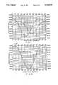
- FIG. 5 is a fragmentary cutaway elevational view of the double action press of the present invention.
- FIG. 6 is a graph of the displacements of the inner and outer slide versus the crank angle of the slides.
- Press 10 includes a crown housing 12 which is supported above the press bed (not shown) by uprights 14.
- a shaft 16 is rotatably supported by shaft bearings 18 and 19 which are fixedly mounted on housing 12.
- a flywheel 20 and V-pulleys 21, driven by a motor (not shown) are fixedly mounted to shaft 16 so as to rotate therewith.
- Attached to the end of shaft 16 is a pulley 22 around which is a belt 24 having the other end in rotational engagement with flywheel and clutch 26.
- Flywheel 20 imparts its rotational inertia through belt 24 and flywheel and clutch 26 to rotate crankshaft 28 connected at one end to clutch 26.
- Crankshaft 28 is rotatably supported in main bearings 30 and 32, and includes a hydraulic brake assembly 34 connected on one end thereof for stopping or slowing crankshaft 28.
- Four intermediate bearings 30, 31, 32 and 33 also rotatably support crankshaft 28.
- Outer slide throws 36 and 38 on crankshaft 28 are respectively radially surrounded by outer slide connections 40 and 42, which are respectively connected to outer pistons 44 and 46 by respective outer wrist pins 48 and 50.
- Outer slide 52 is securely connected to both outer pistons 44 and 46 by bolts 54.
- inner slide throws 56 and 58 on crankshaft 28 are respectively radially surrounded by inner slide connections 60 and 62, which are respectively connected to inner pistons 64 and 66 by respective inner wrist pins 68 and 70.
- Inner slide 72 is securely connected to both inner pistons 64 and 66 by bolts 74.
- a balance throw 76 is centrally located on crankshaft 28 between inner throws 56 and 58. Throw 76 is radially surrounded by balancer slide connection 78 which is connected to balancer 80 through balancer wrist pin 82.
- Outer throws 36 and 38, and inner throws 56 and 58 are eccentric on crankshaft 28 such that, as depicted in FIG. 3, the top of the stroke of inner slide 72 lags the top of the stroke of outer slide 52 by 80°.
- outer slide 52 contacts the stock material before inner slide 72 contacts the stock material.
- FIG. 3 shows that the top of the stroke of balancer 80 lags the top of the stroke of the outer slide by 212°.
- outer throws 36, 38 and inner throws 56, 58 both eccentrically rotate relative to crankshaft 28.
- outer pistons 44, 46 and inner pistons 64, 66 connected to their respective throws by outer connections 40, 42 through inner wrist pins 48, 50 and inner connections 60, 62 through outer wrist pins 68, 70, are vertically reciprocated which in turn vertically reciprocate outer slide 52 and inner slide 72 respectively connected thereto.
- the inner slide 72 has a 5.5 inch stroke and weighs 4,250 pounds with its respective die and is driven two 18 inch long connections, comprising inner slide connections 60, 62 and inner pistons 64, 66 respectively.
- the displacement of outer slide 52 with respect to its crank angle and the displacement of inner slide 72 with respect to its crank angle is plotted to yield outer slide displacement curve 94 and inner slide displacement curve 96.
- the upper apex of both curves correspond to the top of the stroke for that respective slide.
- the crank angle degrees coordinates are chosen so that the top of the stroke for the outer slide 52 occurs at 0°, thus the top of the stroke for the inner slide 72 occurs at an easily discernable angle, here being at 80°.
- Both the outer slide displacement curve 94 and the inner slide displacement curve 96 are substantially periodic sine waves.
- outer slide inertia force curve 84 begins at 0° which corresponds with the top of the stroke for the outer slide and has an inertia force of -52,000 pounds, where the negative sign denotes an upward force.
- Outer slide curve 84 is a substantially periodic sine wave that goes from an upward inertia force (-) of approximately 52,000 pounds to a downward inertia force (+) of approximately 62,000 pounds.
- Inner slide inertia force curve 86 lags outer slide curve 84 by approximately 80° as its top of the stroke occurs at approximately 80° as seen in FIG. 1.
- Inner slide curve 86 is also a substantially periodic sine wave that goes from an upward inertia force (-) of approximately 35,000 pounds to a downward inertia force (+) of approximately 47,000 pounds.
- outer slide curve 84 and inner slide curve 86 are then resolved into a single inertia force resultant slide curve 88 by standard wave superposition.
- Resultant curve 88 is also a substantially periodic sine wave which goes from an upward inertia force (-) of approximately 74,000 pounds to a downward inertia force (+) of approximately 77,000 pounds.
- resultant curve 88 represents the total inertia force exerted on the press by outer slide 52 and inner slide 72.
- resultant curve 88 representing the total inertia force can then be opposed by a 180° phase shifted substantially periodic sine wave of the same magnitude.
- This 180° phase shifted curve is the balancer curve 90 as shown plotted against the resultant curve 88 in FIG. 4. Since the top of the stroke of resultant curve 88 lags outer slide curve 84 (and thus the outer slide 52) by 32°, the top of the stroke of the balancer curve 90 must lag the outer slide curve 84 by 180°+32°, or 212°, diagrammatically shown in FIG. 3. The vertical inertia forces creating the vibration are reduced by the opposing vertical inertia force of the balancer.
- a physical balancer mechanism having a single mass shown as balancer throw 76, balancer connection 78, balancer 80, and balancer wrist pin 82 in FIG. 1, must be chosen which substantially approximates the generated balancer curve 90 should its inertia force be plotted against its crank angle.
- the term "single mass” is defined as a mass or plurality of masses which contemporaneously reciprocate in unison.
- the single mass can consist of a single weight 80 centrally mounted on crankshaft 28 or the single mass may constitute several weights (not shown), in summation equal to the single mass, mounted along crankshaft 28 and reciprocating in unison.
- a single balancer of 13,345 pounds with a 3.25 inch stroke length driven with a 28 inch long connection and phased 212° behind outer slide 52 approximates balancer curve 90.
- the total vertical inertia forces of a double action press generated by the inner and outer slides are balanced by a single balancer mass according to the inventive method within 4-10% of complete balance.
Landscapes
- Engineering & Computer Science (AREA)
- Mechanical Engineering (AREA)
- General Engineering & Computer Science (AREA)
- Physics & Mathematics (AREA)
- Acoustics & Sound (AREA)
- Aviation & Aerospace Engineering (AREA)
- Press Drives And Press Lines (AREA)
- Presses And Accessory Devices Thereof (AREA)
- Mounting, Exchange, And Manufacturing Of Dies (AREA)
Priority Applications (6)
| Application Number | Priority Date | Filing Date | Title |
|---|---|---|---|
| US07/666,255 US5136875A (en) | 1991-03-08 | 1991-03-08 | Single reciprocating dynamic balancer for a double action stamping press |
| DE69202370T DE69202370T2 (de) | 1991-03-08 | 1992-02-26 | Dynamische Massenausgleichsvorrichtung mit einzelnem hin- und herbewegenden Gewicht für eine Stanzpresse mit doppelter Wirkung. |
| EP92103233A EP0503367B1 (fr) | 1991-03-08 | 1992-02-26 | Dispositif d'équilibrage dynamique avec une seule masse à mouvement de va-et-vient pour une presse de découpage à double effet |
| AT92103233T ATE122285T1 (de) | 1991-03-08 | 1992-02-26 | Dynamische massenausgleichsvorrichtung mit einzelnem hin- und herbewegenden gewicht für eine stanzpresse mit doppelter wirkung. |
| CA002062380A CA2062380C (fr) | 1991-03-08 | 1992-03-06 | Equilibreur dynamique simple pour presse a marquer a double action |
| US07/880,542 US5182935A (en) | 1991-03-08 | 1992-05-08 | Single reciprocating dynamic balancer for a double action stamping press |
Applications Claiming Priority (1)
| Application Number | Priority Date | Filing Date | Title |
|---|---|---|---|
| US07/666,255 US5136875A (en) | 1991-03-08 | 1991-03-08 | Single reciprocating dynamic balancer for a double action stamping press |
Related Child Applications (1)
| Application Number | Title | Priority Date | Filing Date |
|---|---|---|---|
| US07/880,542 Division US5182935A (en) | 1991-03-08 | 1992-05-08 | Single reciprocating dynamic balancer for a double action stamping press |
Publications (1)
| Publication Number | Publication Date |
|---|---|
| US5136875A true US5136875A (en) | 1992-08-11 |
Family
ID=24673446
Family Applications (1)
| Application Number | Title | Priority Date | Filing Date |
|---|---|---|---|
| US07/666,255 Expired - Fee Related US5136875A (en) | 1991-03-08 | 1991-03-08 | Single reciprocating dynamic balancer for a double action stamping press |
Country Status (5)
| Country | Link |
|---|---|
| US (1) | US5136875A (fr) |
| EP (1) | EP0503367B1 (fr) |
| AT (1) | ATE122285T1 (fr) |
| CA (1) | CA2062380C (fr) |
| DE (1) | DE69202370T2 (fr) |
Cited By (7)
| Publication number | Priority date | Publication date | Assignee | Title |
|---|---|---|---|---|
| US5735165A (en) * | 1995-06-23 | 1998-04-07 | The Minster Machine Company | Bodymaker drive system |
| US5852970A (en) * | 1995-11-27 | 1998-12-29 | The Minster Machine Company | Underdrive opposing action press |
| US6067886A (en) * | 1996-08-02 | 2000-05-30 | The Vision Limited Partnership | Machine trim press having counterbalance features |
| US6477945B1 (en) * | 1999-09-07 | 2002-11-12 | Aida Engineering, Ltd. | Double-action mechanical press |
| US20030024295A1 (en) * | 2001-06-09 | 2003-02-06 | Daniel Edward A. | T-gib dynamic balancer weight guide |
| US20100043739A1 (en) * | 2008-08-25 | 2010-02-25 | Hyundai Motor Company | Balance weight system of crankshaft |
| CN109228447A (zh) * | 2018-11-13 | 2019-01-18 | 张彪 | 一种机械加工模具加热压合成型装置 |
Citations (10)
| Publication number | Priority date | Publication date | Assignee | Title |
|---|---|---|---|---|
| US2357557A (en) * | 1940-08-03 | 1944-09-05 | Henry & Wright Mfg Company | Dieing machine |
| US2610524A (en) * | 1948-06-23 | 1952-09-16 | Frederick K Maust | Counterbalancing device |
| US3450038A (en) * | 1967-04-04 | 1969-06-17 | Bliss Co | High speed press |
| US3611918A (en) * | 1969-09-29 | 1971-10-12 | Perkins Machine Co | Press |
| DE2444083A1 (de) * | 1973-10-23 | 1975-04-24 | Minster Machine Co | Mechanische presse, insbesondere napfziehpresse |
| DE2806976A1 (de) * | 1977-02-22 | 1978-08-31 | Vyzk Ustav Tvarecich Stroju | Vorrichtung zur auswuchtung des stoessels einer umformmaschine, insbesondere eines stoessels einer stufenpresse |
| DE3040686A1 (de) * | 1980-10-29 | 1982-05-27 | Volkswagenwerk Ag, 3180 Wolfsburg | Massenausgleichseinrichtung |
| US4674357A (en) * | 1984-04-27 | 1987-06-23 | Aida Engineering, Ltd. | Balancing device for press |
| US4757734A (en) * | 1986-04-28 | 1988-07-19 | Bruderer Ag | Balancing means in a punching machine |
| US4890524A (en) * | 1988-08-31 | 1990-01-02 | John Brown Inc. | Trim press with counterbalance |
Family Cites Families (3)
| Publication number | Priority date | Publication date | Assignee | Title |
|---|---|---|---|---|
| US4376410A (en) * | 1981-09-08 | 1983-03-15 | The Minster Machine Company | Press guide structure |
| JPS6018519B2 (ja) * | 1982-08-30 | 1985-05-10 | 株式会社山田ドビ− | プレスのための平衡装置 |
| EP0248917B1 (fr) * | 1986-06-06 | 1991-02-20 | L. SCHULER GmbH | Dispositif de réglage de la course du coulisseau dans une presse à arbre à excentrique |
-
1991
- 1991-03-08 US US07/666,255 patent/US5136875A/en not_active Expired - Fee Related
-
1992
- 1992-02-26 DE DE69202370T patent/DE69202370T2/de not_active Expired - Fee Related
- 1992-02-26 EP EP92103233A patent/EP0503367B1/fr not_active Expired - Lifetime
- 1992-02-26 AT AT92103233T patent/ATE122285T1/de not_active IP Right Cessation
- 1992-03-06 CA CA002062380A patent/CA2062380C/fr not_active Expired - Fee Related
Patent Citations (10)
| Publication number | Priority date | Publication date | Assignee | Title |
|---|---|---|---|---|
| US2357557A (en) * | 1940-08-03 | 1944-09-05 | Henry & Wright Mfg Company | Dieing machine |
| US2610524A (en) * | 1948-06-23 | 1952-09-16 | Frederick K Maust | Counterbalancing device |
| US3450038A (en) * | 1967-04-04 | 1969-06-17 | Bliss Co | High speed press |
| US3611918A (en) * | 1969-09-29 | 1971-10-12 | Perkins Machine Co | Press |
| DE2444083A1 (de) * | 1973-10-23 | 1975-04-24 | Minster Machine Co | Mechanische presse, insbesondere napfziehpresse |
| DE2806976A1 (de) * | 1977-02-22 | 1978-08-31 | Vyzk Ustav Tvarecich Stroju | Vorrichtung zur auswuchtung des stoessels einer umformmaschine, insbesondere eines stoessels einer stufenpresse |
| DE3040686A1 (de) * | 1980-10-29 | 1982-05-27 | Volkswagenwerk Ag, 3180 Wolfsburg | Massenausgleichseinrichtung |
| US4674357A (en) * | 1984-04-27 | 1987-06-23 | Aida Engineering, Ltd. | Balancing device for press |
| US4757734A (en) * | 1986-04-28 | 1988-07-19 | Bruderer Ag | Balancing means in a punching machine |
| US4890524A (en) * | 1988-08-31 | 1990-01-02 | John Brown Inc. | Trim press with counterbalance |
Cited By (8)
| Publication number | Priority date | Publication date | Assignee | Title |
|---|---|---|---|---|
| US5735165A (en) * | 1995-06-23 | 1998-04-07 | The Minster Machine Company | Bodymaker drive system |
| US5852970A (en) * | 1995-11-27 | 1998-12-29 | The Minster Machine Company | Underdrive opposing action press |
| US6067886A (en) * | 1996-08-02 | 2000-05-30 | The Vision Limited Partnership | Machine trim press having counterbalance features |
| US6477945B1 (en) * | 1999-09-07 | 2002-11-12 | Aida Engineering, Ltd. | Double-action mechanical press |
| US20030024295A1 (en) * | 2001-06-09 | 2003-02-06 | Daniel Edward A. | T-gib dynamic balancer weight guide |
| US7111549B2 (en) | 2001-06-09 | 2006-09-26 | The Minster Machine Company | T-gib dynamic balancer weight guide |
| US20100043739A1 (en) * | 2008-08-25 | 2010-02-25 | Hyundai Motor Company | Balance weight system of crankshaft |
| CN109228447A (zh) * | 2018-11-13 | 2019-01-18 | 张彪 | 一种机械加工模具加热压合成型装置 |
Also Published As
| Publication number | Publication date |
|---|---|
| DE69202370D1 (de) | 1995-06-14 |
| EP0503367A2 (fr) | 1992-09-16 |
| EP0503367B1 (fr) | 1995-05-10 |
| CA2062380C (fr) | 1995-02-14 |
| ATE122285T1 (de) | 1995-05-15 |
| EP0503367A3 (en) | 1993-02-24 |
| DE69202370T2 (de) | 1995-12-14 |
Similar Documents
| Publication | Publication Date | Title |
|---|---|---|
| US3808912A (en) | Arrangement for dynamic balancing of a mechanical press, especially a high speed mechanical press | |
| US4966042A (en) | Balanced reciprocating machines | |
| US5544577A (en) | Mechanical pressing machine with means for cancelling load fluctuation torque | |
| US4138897A (en) | Balanced crankshaft mechanism for the two piston Stirling engine | |
| KR101169255B1 (ko) | 압연기, 특히 냉간 필거 압연기를 위한 구동 장치 | |
| US5852970A (en) | Underdrive opposing action press | |
| US5136875A (en) | Single reciprocating dynamic balancer for a double action stamping press | |
| JPS5833944B2 (ja) | 4気筒複動熱ガスエンジン | |
| US5182935A (en) | Single reciprocating dynamic balancer for a double action stamping press | |
| ES461340A1 (es) | Motor bicilindrico en linea perfeccionado. | |
| US5201267A (en) | Balance mechanism for a press machine | |
| US4800852A (en) | Inline counterbalance weight system for a single cylinder engine | |
| GB1371803A (en) | Apparatus for fatigue testing of coiled springs | |
| JP3318071B2 (ja) | 機械式プレス装置 | |
| US5735165A (en) | Bodymaker drive system | |
| US3776046A (en) | Inertia balancing means for power presses | |
| US3797327A (en) | Arrangement for dynamic balancing of a high speed press | |
| RU2247614C1 (ru) | Приводная система для прокатного стана | |
| US5239921A (en) | Balance mechanism for a press machine | |
| JPS5950439B2 (ja) | コウソクカイテンニオイテ ドウテキニバランススルプレスキカイ | |
| JPS63101539A (ja) | 機関のバランスシヤフト駆動装置 | |
| US5615569A (en) | Wobble press | |
| JPH1110399A (ja) | プレス機械の動的バランス装置 | |
| JPS58157598A (ja) | 機械プレスの平衡装置 | |
| JPS63168300A (ja) | 合成軌跡クランクプレス |
Legal Events
| Date | Code | Title | Description |
|---|---|---|---|
| AS | Assignment |
Owner name: MINSTER MACHINE COMPANY, THE, 240 WEST FIFTH STREE Free format text: ASSIGNMENT OF ASSIGNORS INTEREST.;ASSIGNOR:SCHOCKMAN, ROBERT L.;REEL/FRAME:005636/0675 Effective date: 19910306 |
|
| FEPP | Fee payment procedure |
Free format text: PAYOR NUMBER ASSIGNED (ORIGINAL EVENT CODE: ASPN); ENTITY STATUS OF PATENT OWNER: LARGE ENTITY |
|
| FPAY | Fee payment |
Year of fee payment: 4 |
|
| REMI | Maintenance fee reminder mailed | ||
| LAPS | Lapse for failure to pay maintenance fees | ||
| FP | Lapsed due to failure to pay maintenance fee |
Effective date: 20000811 |
|
| STCH | Information on status: patent discontinuation |
Free format text: PATENT EXPIRED DUE TO NONPAYMENT OF MAINTENANCE FEES UNDER 37 CFR 1.362 |