US5143524A - Electrostatic particle filtration - Google Patents
Electrostatic particle filtration Download PDFInfo
- Publication number
- US5143524A US5143524A US07/481,854 US48185490A US5143524A US 5143524 A US5143524 A US 5143524A US 48185490 A US48185490 A US 48185490A US 5143524 A US5143524 A US 5143524A
- Authority
- US
- United States
- Prior art keywords
- electrical potential
- potential difference
- sets
- circuitry
- vacuum cleaner
- Prior art date
- Legal status (The legal status is an assumption and is not a legal conclusion. Google has not performed a legal analysis and makes no representation as to the accuracy of the status listed.)
- Expired - Lifetime
Links
- 238000001914 filtration Methods 0.000 title claims abstract description 31
- 239000002245 particle Substances 0.000 title claims description 31
- 239000013618 particulate matter Substances 0.000 claims abstract description 23
- 230000005684 electric field Effects 0.000 claims abstract description 18
- 238000009413 insulation Methods 0.000 claims description 15
- RYGMFSIKBFXOCR-UHFFFAOYSA-N Copper Chemical compound [Cu] RYGMFSIKBFXOCR-UHFFFAOYSA-N 0.000 claims description 3
- XAGFODPZIPBFFR-UHFFFAOYSA-N aluminium Chemical compound [Al] XAGFODPZIPBFFR-UHFFFAOYSA-N 0.000 claims description 3
- 229910052782 aluminium Inorganic materials 0.000 claims description 3
- 238000000034 method Methods 0.000 claims description 3
- 239000000428 dust Substances 0.000 claims description 2
- 239000012777 electrically insulating material Substances 0.000 claims 5
- 229910052802 copper Inorganic materials 0.000 claims 1
- 239000010949 copper Substances 0.000 claims 1
- 238000007599 discharging Methods 0.000 claims 1
- 239000007787 solid Substances 0.000 claims 1
- 239000000463 material Substances 0.000 abstract description 26
- 238000009825 accumulation Methods 0.000 abstract description 3
- 230000000717 retained effect Effects 0.000 abstract description 3
- 239000011882 ultra-fine particle Substances 0.000 abstract 1
- 150000002500 ions Chemical class 0.000 description 12
- TWNQGVIAIRXVLR-UHFFFAOYSA-N oxo(oxoalumanyloxy)alumane Chemical compound O=[Al]O[Al]=O TWNQGVIAIRXVLR-UHFFFAOYSA-N 0.000 description 5
- 239000004744 fabric Substances 0.000 description 3
- 241000894006 Bacteria Species 0.000 description 2
- 206010020751 Hypersensitivity Diseases 0.000 description 2
- PXHVJJICTQNCMI-UHFFFAOYSA-N Nickel Chemical compound [Ni] PXHVJJICTQNCMI-UHFFFAOYSA-N 0.000 description 2
- 239000004809 Teflon Substances 0.000 description 2
- 229920006362 Teflon® Polymers 0.000 description 2
- 238000007792 addition Methods 0.000 description 2
- 208000026935 allergic disease Diseases 0.000 description 2
- 230000009286 beneficial effect Effects 0.000 description 2
- 239000004020 conductor Substances 0.000 description 2
- 238000010292 electrical insulation Methods 0.000 description 2
- 239000010419 fine particle Substances 0.000 description 2
- 239000004033 plastic Substances 0.000 description 2
- 230000010287 polarization Effects 0.000 description 2
- 239000000843 powder Substances 0.000 description 2
- BFKJFAAPBSQJPD-UHFFFAOYSA-N tetrafluoroethene Chemical compound FC(F)=C(F)F BFKJFAAPBSQJPD-UHFFFAOYSA-N 0.000 description 2
- 239000002759 woven fabric Substances 0.000 description 2
- 241000238876 Acari Species 0.000 description 1
- 239000004677 Nylon Substances 0.000 description 1
- 239000011230 binding agent Substances 0.000 description 1
- 239000011248 coating agent Substances 0.000 description 1
- 238000000576 coating method Methods 0.000 description 1
- 238000010276 construction Methods 0.000 description 1
- 230000007423 decrease Effects 0.000 description 1
- 238000012217 deletion Methods 0.000 description 1
- 230000037430 deletion Effects 0.000 description 1
- 210000003298 dental enamel Anatomy 0.000 description 1
- 238000004720 dielectrophoresis Methods 0.000 description 1
- 238000001962 electrophoresis Methods 0.000 description 1
- PCHJSUWPFVWCPO-UHFFFAOYSA-N gold Chemical compound [Au] PCHJSUWPFVWCPO-UHFFFAOYSA-N 0.000 description 1
- 229910052737 gold Inorganic materials 0.000 description 1
- 239000010931 gold Substances 0.000 description 1
- 231100000206 health hazard Toxicity 0.000 description 1
- 239000011810 insulating material Substances 0.000 description 1
- 230000014759 maintenance of location Effects 0.000 description 1
- 238000012986 modification Methods 0.000 description 1
- 230000004048 modification Effects 0.000 description 1
- 230000007935 neutral effect Effects 0.000 description 1
- 229910052759 nickel Inorganic materials 0.000 description 1
- 229920001778 nylon Polymers 0.000 description 1
- 239000008188 pellet Substances 0.000 description 1
- 230000000135 prohibitive effect Effects 0.000 description 1
- 230000001846 repelling effect Effects 0.000 description 1
- 238000005728 strengthening Methods 0.000 description 1
- 238000011144 upstream manufacturing Methods 0.000 description 1
Images


Classifications
-
- A—HUMAN NECESSITIES
- A47—FURNITURE; DOMESTIC ARTICLES OR APPLIANCES; COFFEE MILLS; SPICE MILLS; SUCTION CLEANERS IN GENERAL
- A47L—DOMESTIC WASHING OR CLEANING; SUCTION CLEANERS IN GENERAL
- A47L9/00—Details or accessories of suction cleaners, e.g. mechanical means for controlling the suction or for effecting pulsating action; Storing devices specially adapted to suction cleaners or parts thereof; Carrying-vehicles specially adapted for suction cleaners
- A47L9/10—Filters; Dust separators; Dust removal; Automatic exchange of filters
- A47L9/14—Bags or the like; Rigid filtering receptacles; Attachment of, or closures for, bags or receptacles
-
- A—HUMAN NECESSITIES
- A47—FURNITURE; DOMESTIC ARTICLES OR APPLIANCES; COFFEE MILLS; SPICE MILLS; SUCTION CLEANERS IN GENERAL
- A47L—DOMESTIC WASHING OR CLEANING; SUCTION CLEANERS IN GENERAL
- A47L13/00—Implements for cleaning floors, carpets, furniture, walls, or wall coverings
- A47L13/10—Scrubbing; Scouring; Cleaning; Polishing
- A47L13/40—Cleaning implements actuated by electrostatic attraction; Devices for cleaning same; Magnetic cleaning implements
-
- A—HUMAN NECESSITIES
- A47—FURNITURE; DOMESTIC ARTICLES OR APPLIANCES; COFFEE MILLS; SPICE MILLS; SUCTION CLEANERS IN GENERAL
- A47L—DOMESTIC WASHING OR CLEANING; SUCTION CLEANERS IN GENERAL
- A47L9/00—Details or accessories of suction cleaners, e.g. mechanical means for controlling the suction or for effecting pulsating action; Storing devices specially adapted to suction cleaners or parts thereof; Carrying-vehicles specially adapted for suction cleaners
- A47L9/10—Filters; Dust separators; Dust removal; Automatic exchange of filters
- A47L9/12—Dry filters
-
- B—PERFORMING OPERATIONS; TRANSPORTING
- B03—SEPARATION OF SOLID MATERIALS USING LIQUIDS OR USING PNEUMATIC TABLES OR JIGS; MAGNETIC OR ELECTROSTATIC SEPARATION OF SOLID MATERIALS FROM SOLID MATERIALS OR FLUIDS; SEPARATION BY HIGH-VOLTAGE ELECTRIC FIELDS
- B03C—MAGNETIC OR ELECTROSTATIC SEPARATION OF SOLID MATERIALS FROM SOLID MATERIALS OR FLUIDS; SEPARATION BY HIGH-VOLTAGE ELECTRIC FIELDS
- B03C3/00—Separating dispersed particles from gases or vapour, e.g. air, by electrostatic effect
- B03C3/02—Plant or installations having external electricity supply
- B03C3/04—Plant or installations having external electricity supply dry type
- B03C3/14—Plant or installations having external electricity supply dry type characterised by the additional use of mechanical effects, e.g. gravity
- B03C3/155—Filtration
Definitions
- This invention relates generally and is applicable to most forms of electrostatic filtration. It relates more particularly to an on-board electrostatic filter for trapping minute particles picked up by a vacuum cleaner and propelled into its dirt collector.
- An important application of the present invention is in vacuum cleaners.
- Such machines include apparatus for applying suction to dislodge undesirable particulate matter from a surface to be cleaned, by generating a high velocity air flow.
- the suction apparatus includes structure for channelling the dirt-laden air into a narrow stream.
- a collection bag or other receptacle is mounted to receive the particle and air flow.
- a typical bag includes a jacket formed of air pervious material, such as paper and/or tightly woven fabric, to mechanically filter particulate matter, while allowing the filtered air to dissipate outwardly through the bag and back into the external environment.
- Vacuum cleaners which rely solely on mechanical filtration, however, filter only particles of greater than a given size, while allowing smaller particles to pass through the filter and re-enter the external environment. This is because, in order to permit the air to pass freely out of the bag, the interstices in the paper or fabric, which permit air to pass through, cannot be too small. Otherwise, the suction air stream is inhibited, and air velocity becomes too low for good suction. While one could increase suction and air volume by use of more powerful electric motor drive systems, the use of inordinately large and heavy electric motors in a household appliance such a vacuum cleaner can become both impractical and uneconomical. The weight and cost of large motors make their use prohibitive in vacuum cleaners designed for household use.
- the fine particles that pass through the bag and back into the external environment can include very small dust particles, contributing to odor and re-accumulation.
- Other particles escaping filtration are allergy-aggravating pollen and bacteria, as well as mites, which can be a health hazard.
- the elements are positioned in the particle-laden air stream.
- a charged element as noted above, attracts oppositely charged particles passing along in the air stream. Moreover, even some neutrally charged particles are attracted to the element by a phenomenon known as dielectrophoresis.
- corona It has also been proposed to augment such electrostatic filtration by provision of a so-called "corona” device in the air stream.
- a corona device produces an electrical space charge which is distributed generally throughout a region. Such space charge, if generated in the particle-laden air stream, pre-charges the particles. This imposition of charge on the particle increases the force attracting or repelling them to the electrically polarized filter element.
- a further proposal has been to place in the air stream a piece of electrically charged fleece.
- Electrode material Another type of device for electrostatic filtering incorporates what is known as "electret” material.
- Electret materials have low electrical conductivity and usually have dielectric properties as well. They also have the property of retaining charge polarization for a long time. Electret materials have been used as electrostatic filters in surgical masks.
- the filter equipment described above has a further disadvantage.
- a charged surface "loads up" with accumulated particles, the charge on the charged filter element can become neutralized or canceled, due to the opposite polarization of particles and ions attracted to its surfaces. This tends to cancel the generated electrical fields, hindering or totally disabling operation of the device.
- An object of this invention is to provide electrostatic filtering apparatus and circuitry (1) whose effectiveness does not deteriorate as the amount of retained filtered material increases, (2) which is effective at low operating voltages, and (3) which is lightweight, relatively inexpensive and compact.
- the disadvantages of the prior art are reduced or eliminated by the provision of a vacuum cleaner having a new and improved on-board electrostatic filtration system.
- the electrostatic filtration system includes a mesh finely woven of two sets of conductive filaments or fine wires which are electrically insulated one from another.
- a source of electrical potential is coupled to apply an electrical potential difference between the two sets of conductive filaments or wires.
- Circuitry is provided for repeatedly reversing the polarity of the electrical potential applied between the sets of conductive filaments or wires.
- the mesh is located within the vacuum cleaner's dirt receptacle, which typically is a bag.
- the mesh has an expanse large enough to cover a substantial portion of the interior of the bag.
- the reversal in polarity of the applied electrical potential difference assists in maintaining filtration effectiveness which would otherwise be degraded by the accumulation of a substantial layer of filtered particulate matter on the mesh, and by attraction to the mesh of oppositely charged neutrally occurring ions.
- the voltage polarity is abruptly reversed, the resulting suddenly reversed charge polarity on the wire insulation surface adds directly to other charge already on the nearby particles and which is left over from the previous cycle. This restores, and actually increase, the strength of the electrical field produced by the electrical potential difference applied, to achieve better electrostatic filtering results.
- the frequency of voltage polarity reversal is low, on the order of about one cycle per second or less.
- the low frequency allows for the desirable electrostatic phenomena to occur, while still providing for repeated polarity reversal to restore and magnify the filtering electric fields produced by the electrified mesh.
- stages of mesh are used.
- the stages are serially stacked in the air flow, and function together to filter the discharge air more thoroughly than a single mesh.
- a fibrous mechanical filter can be added in series with a mesh for enhanced filtration.
- a suitable high permitivity material comprises aluminum oxide powder.
- Another specific embodiment, applicable to a multi-stage construction involves the staggered placement of successive meshes. Such staggered placement increases the density of charged wire distribution across the cross section of the air stream, without appreciably increasing resistance to the air flow.
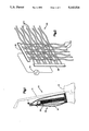
- FIG. 1 is a pictorial side view partly broken away and partly in phantom, illustrating a vacuum cleaner incorporating an embodiment of the present invention.
- FIG. 2 is a pictorial detail view showing a portion of the vacuum cleaner of FIG. 1;
- FIG. 3 is a detailed pictorial view illustrating a portion of the vacuum cleaner of FIG. 1 incorporating another embodiment of the present invention
- FIG. 4 shows an embodiment alternative to that of FIG. 3
- FIG. 5 is a detail elevational view illustrating a portion of the structure shown in FIG. 2 and incorporating an alternate embodiment of the present invention
- FIG. 6 is an elevational detail view illustrating a portion of the structure shown in FIG. 2 and incorporating another alternate embodiment of the present invention
- FIG. 7 is a detail showing of a portion of the structure shown in FIG. 2, showing another alternate embodiment of the invention.
- FIG. 8 is a schematic drawing of a circuit which constitutes a portion of an embodiment of the present invention.
- FIG. 9 is a tabular rendition describing an aspect of the operation of the present invention.
- FIG. 1 shows a vacuum cleaner 10 which incorporates the present inventive apparatus and circuitry for electrostatically filtering very fine particulate matter picked up by the vacuum cleaner. While the present invention is described in the environment of a vacuum cleaner, the invention is not limited to that particular application. Rather, the invention is believed applicable generally to electrostatic filtering in virtually any environment.
- the vacuum cleaner 10 in which the present invention is incorporated is of otherwise known type.
- a vacuum cleaner suitably incorporating the present invention is a Kirby Model, manufactured by Kirby Division, The Scott-Fetzer Company, Cleveland, Ohio, U.S.A.
- the vacuum cleaner includes a housing 12 and a handle 14 pivotally mounted to the housing (both in phantom).
- the housing 12 encloses a known electric motor and blower combination (not shown).
- the blower/motor combination when actuated, generates a high velocity air stream for providing suction, and ducting (also not shown) for applying the generated suction to a region below the underside of the housing 12.
- the suction so generated dislodges dirt and other particulate matter from a surface on which the housing rests.
- the air stream generated by the blower/motor combination thus becomes laden with the particulate matter.
- the ducting structure within the housing defines a discharge opening (not shown) near the rear of the housing 12.
- the particle-laden air stream is discharged from the discharge opening into a collection receptacle generally indicated by the reference character 16.
- the collection receptacle 16 comprises a flexible bag having an opening which is removably attachable to position the opening to receive the particle-laden air flow discharge.
- the collection bag 16 includes an air pervious outer jacket 18 made of finely woven fabric.
- the collection receptacle optionally further includes an inner air pervious and disposable filter paper liner.
- the collection bag 16 of FIG. 1 is shown partially broken away to illustrate a multi-element structure, generally indicated by the reference character 20.
- This structure constitutes a portion of apparatus and circuitry comprising an electrostatic filtering unit according to the present invention.
- the structure 20 is illustrated in more detail in FIG. 2.
- the structure 20 comprises a fine electrically conductive wire mesh, or cloth.
- the wire mesh 20 includes two sets of interlaced fine conductive filaments or wires.
- a first set of conductive wires extends generally horizontally as illustrated in FIG. 2.
- a second set of conductive wires extends generally vertically in FIG. 2. Representatives of the first set of wires are indicated collectively by reference character 22. Representatives of the second set of wires are denoted collectively by reference character 24.
- Each of the individual wires of the sets 22, 24 are electrically insulated.
- Each of the wires making up the mesh comprises a copper wire approximately 0.002 inches in diameter and covered by a thin insulating material, in this case a coating of enamel.
- each of the wires of the mesh comprises an aluminum wire of approximately 0.002 inches in diameter.
- aluminum aluminum oxide which naturally forms in the presence of air on the outside surface of the wires provides the needed insulation.
- the mesh 20 can optionally comprise filaments of known types of conductive plastic material.
- Each of the first set of conductors 22 is conductively coupled at one end, by gold or nickel contacts, to a common busbar 26.
- Each of the second set of conductive wires 24 is conductively coupled at one end by similar contacts, to a busbar 28.
- the first and second sets of conductors 22, 24 correspond, in Weaver's terminology, to the "warp” and "weft” of cloth.
- a source 30 of alternating electrical voltage is coupled between the busbars 26, 28.
- the source 30 applies a square wave having peak voltage of approximately 9 volts positive and negative, to the busbar 28.
- the busbar 26 is substantially grounded.
- the source 30 can be constructed from the combination of a 9 volt battery and a polarity reversing switch, circuitry well within the ordinary skill in the art, given the present disclosure.
- the battery can be disposable. Alternately, the battery can be of the rechargeable variety. In such an instance, the recharging of the battery can be accomplished by known apparatus and circuitry coupled to draw power from the main power operating system of the vacuum cleaner.
- the ends of the wires 24 of the second set opposite the busbar 28 also terminate in electrical insulation.
- This configuration renders the electrical source 30, combined with the wire sets 22, 24, a primarily capacitive open circuit, rather than a resistive circuit.
- the circuit is not conductively closed. As such, the current flow in the circuit, and the power consumed, is extremely small. Such low power requirements make it possible for the 9 volt battery to be very small and lightweight. This contributes to the portability, simplicity, and economy of the vacuum cleaner 10 with which the electrostatic filter is associated.
- a suitable frequency of electric polarity reversal, or alternation, for improving filtration effectiveness is on the order of one cycle per second, or lower, down to about one cycle every 20 minutes. It is believed, however, that selection of the optimum frequency of operation depends on other parameters of the system, such as wire diameter and the size of the interstices of the mesh, along with air flow velocity, voltage, humidity, etc.
- a low frequency of reversal is of value in all instances. Low frequency allows time between reversals for the circuit to reach a steady state and for beneficial electrostatic phenomena, described in more detail below, to occur.
- the mesh 20 is located within the collection bag 16, near the inner surface of the outer jacket portion 18.
- the mesh 20 is of sufficient lateral expanse to enable it to cover a substantial portion of the interior of the bag jacket.
- the mesh 20 intercepts the particle-laden air stream discharged into the bag.
- Filtered particles include allergy-causing pollen, which can be very small, and can even include bacteria, thus removing from the air a substantial amount of these health-hazardous organisms.
- the alternation, or reversal, of the polarity of the voltage applied between the first and second sets of wires of the mesh 20 helps maintain filtration performance even as the mesh begins to "load up” with accumulated trapped particulate matter, and with atmospheric ions. If the polarity of the voltage were always constant, accumulated particles and ions on the wires would inhibit further attraction and retention of other particles.
- the residual charge will decline only gradually, not all at one, after polarity reversal. Over time, however, the residual charge on the particles will decay. This is mainly due to oppositely charged particles and ions which are attracted to the wire insulation surface after its polarity goes negative.
- the charge reversal will cause some of the particles to move and adhere to the wires of the opposite set in the mesh.
- FIG. 3 illustrates an embodiment of the present invention incorporating multiple, serially arranged conductive wire meshes 32, 34, 36.
- Each of the meshes, 32, 34, 36 is the same as the mesh 20 illustrated in FIG. 2 and described in connection with that Figure.
- An alternating voltage source 40 is connected in parallel to the respective wire sets of each of the meshes 32, 34, 36.
- the circuitry and apparatus constituting the source 40 are the same as in the voltage source 30 illustrated in FIG. 2.
- the conductive wire meshes 32, 34, 36 are arranged serially with respect to air flow within the collection bag 16. For the purposes of FIG. 3, the direction of air flow is indicated by an arrow 42.
- the advantage of the multiple mesh embodiment of FIG. 3 is that the three meshes 32, 34, 36, acting serially in conjunction with one another, can normally be expected to attract and retain more of the fine particulate matter present in the air stream.
- a layer of fibrous mechanical filter material can be added between the mesh stages.
- FIG. 3 illustrates the alternating polarity voltage source 40 as a single source connected in parallel to each of the meshes 32, 34, 36
- the source 40 with its parallel connections to each of the meshes, could be replaced by an individual similar source each dedicated to a single one of the meshes 32, 34, 36.
- the use of individual sources for each of the meshes of FIG. 3 enables the polarity reversals on the three meshes to take place spaced in time from one another, rather than in unison, as in the FIG. 3 embodiment where the parallel coupled source 40 is used. Individual sources each coupled to a different mesh enable a sequential polarity reversal.
- FIG. 4 illustrates another embodiment of the present invention employing multiple meshes in a staggered configuration.
- FIG. 4 illustrates two serially arranged meshes 44, 46.
- the mesh 44 is located upstream, relative to the air flow, with respect to the mesh 46.
- FIG. 4 illustrates the mesh 44 as diagonally staggered with respect to the mesh 46.
- the amount of this diagonal staggering is such that the intersections of wires, such as 48, in the mesh 44 are located approximately in the center of the interstices of the mesh 46. This staggering increases the density of charged wires disposed in the air stream, without substantially increasing resistance to the air stream.
- filtration performance can be improved by the addition of a high permitivity material in, or between, the woven meshes.
- a suitable material has been found to comprise aluminum oxide grit.
- FIG. 5 shows a pair of vertically extending wires 60, 62.
- FIG. 5 is a view looking at two meshes edgewise.
- FIG. 5 is simplified for purposes of clarity, with the wires 60, 62 being isolated single vertical wires of adjacent meshes.
- the high permitivity material substantially fills the space between the adjacent meshes.
- the high permitivity material 64 comprises particles of aluminum oxide of the order of microns in diameter, held together, if need be, by a suitable insulative binder which can be provided by one of ordinary skill in the art.
- a suitable insulative binder which can be provided by one of ordinary skill in the art. The presence of this fine powder material between the meshes and in the vicinity of the conductive wires enhances the magnitude of the electric field which can be achieved between wires for a given voltage difference.
- the high permitivity material such as aluminum oxide
- the high permitivity material can be supported on a nylon mesh substraight, or can be impregnated into fused pellets made of the material commonly known by the trademark "TEFLON”.
- FIG. 6 illustrates a similar pair of wires 68, 70, but in this embodiment the high permitivity material is present not only between the meshes, as at reference character 72, but also extends through the meshes to the exterior, such as shown at reference characters 74, 76.
- FIG. 7 illustrates still another manner of employing the high permitivity material.
- FIG. 7 illustrates a single mesh 80.
- the high permitivity material is applied locally between each intersection of a horizontal and vertical wire, as shown for example at reference character 82.
- the electrostatic filtration unit 20 can be supplemented by inclusion in the vacuum cleaner of a corona discharge device in the dirty air stream.
- the corona discharge device imparts an electrical charge to dirt and other particulate matter passing through its corona. This additional charge renders the particles more susceptible of capture by the electrostatic filtration unit 20.
- a triboelectric device which can comprise tubes made of a plastic material known by the trademark TEFLON, can also impart an electrical charge to particles passing in the vicinity.
- the alternating voltage source such as at reference character 30 in FIG. 2 and 40 in FIG. 3, can comprise a 9 volt small lightweight battery in series with a polarity reversing switch.
- FIG. 8 illustrates in schematic form a circuit for providing a low voltage alternating polarity signal suitable for use in the present device.
- the circuit is generally indicated by the reference character 100.
- the circuit produces a low voltage alternating polarity output at a lead 101.
- the output 101 is fed by the output of an 8 position dip switch 102.
- the inputs to the dip switch 102 are provided by a seven stage clocking circuit 104. In operation, only one of the switching elements of the dip switch 102 is set to provide a conductive path from one of the inputs of the dip switch to a corresponding one of its outputs.
- the dip switch is used to divide the output of the clocking circuit 104 according to the respective significant bits of the outputs of the clock.
- the output appearing at the lead 101 has a frequency of reversal which is a function of which one of the output bits of the clock is selected by the setting of the dip switch 102.
- the clocking signal is supplied to the clocking circuit 104 at a lead 106.
- the frequency of the clocking signal can be adjusted by adjusting the setting of a potentiometer 110. This operation is described in more detail in connection with FIG. 9.
- FIG. 9 is a tabular rendition illustrating the functioning of the switching circuit 100.
- the upper table of FIG. 9 correlates the selected position of the dip switch 102 with the amount of time elapsing between successive reversals of polarity of the voltage applied to the meshes.
- the amount of time between successive polarity reversals can be selected to vary in increments between 1 second and 64 seconds. This corresponds to a frequency of alternation of between 30 cycles per minute and about 1/2 cycle per minute.
- switching frequency can be obtained by adjusting the potentiometer 110 in the switching circuit 100.
- the upper table of FIG. 9, described above, corresponds to the switching times which are available with the potentiometer turned to one extreme position.
- the table constituting the bottom portion of FIG. 9 gives the analogous switching times with the potentiometer in its opposite extreme position. As can be seen from the bottom table, with the potentiometer in its opposite position, switching times range between about 7 seconds and 448 seconds.
- the switching frequency can be adjusted to a virtual infinity of values between one switching per second and one switching per 448 seconds.
Landscapes
- Engineering & Computer Science (AREA)
- Mechanical Engineering (AREA)
- Filters For Electric Vacuum Cleaners (AREA)
- Filtering Materials (AREA)
- Electrostatic Separation (AREA)
Priority Applications (6)
| Application Number | Priority Date | Filing Date | Title |
|---|---|---|---|
| US07/481,854 US5143524A (en) | 1990-02-20 | 1990-02-20 | Electrostatic particle filtration |
| JP33087090A JP2934498B2 (ja) | 1990-02-20 | 1990-11-30 | 真空掃除器,真空掃除方法,空気流から粒子状物体を濾過する方法,その装置およびそのシステム |
| EP90313477A EP0443254A1 (fr) | 1990-02-20 | 1990-12-11 | Filtration électrostatique de particules |
| CA002036739A CA2036739C (fr) | 1990-02-20 | 1991-02-20 | Methode de filtration electrostatique |
| US07/909,082 US5376168A (en) | 1990-02-20 | 1992-06-05 | Electrostatic particle filtration |
| US08/125,076 US5405434A (en) | 1990-02-20 | 1993-09-22 | Electrostatic particle filtration |
Applications Claiming Priority (1)
| Application Number | Priority Date | Filing Date | Title |
|---|---|---|---|
| US07/481,854 US5143524A (en) | 1990-02-20 | 1990-02-20 | Electrostatic particle filtration |
Related Child Applications (1)
| Application Number | Title | Priority Date | Filing Date |
|---|---|---|---|
| US07/909,082 Continuation-In-Part US5376168A (en) | 1990-02-20 | 1992-06-05 | Electrostatic particle filtration |
Publications (1)
| Publication Number | Publication Date |
|---|---|
| US5143524A true US5143524A (en) | 1992-09-01 |
Family
ID=23913657
Family Applications (1)
| Application Number | Title | Priority Date | Filing Date |
|---|---|---|---|
| US07/481,854 Expired - Lifetime US5143524A (en) | 1990-02-20 | 1990-02-20 | Electrostatic particle filtration |
Country Status (4)
| Country | Link |
|---|---|
| US (1) | US5143524A (fr) |
| EP (1) | EP0443254A1 (fr) |
| JP (1) | JP2934498B2 (fr) |
| CA (1) | CA2036739C (fr) |
Cited By (18)
| Publication number | Priority date | Publication date | Assignee | Title |
|---|---|---|---|---|
| US5400465A (en) * | 1994-03-30 | 1995-03-28 | Home Care Industries, Inc. | Vacuum cleaner with charge generator and bag therefor |
| US5466279A (en) * | 1990-11-30 | 1995-11-14 | Kabushiki Kaisha Toshiba | Electric dust collector system |
| US5492677A (en) * | 1993-06-02 | 1996-02-20 | Ajiawasu Kabushiki Kaisha | Contaminated air purifying apparatus |
| US5547493A (en) * | 1994-12-08 | 1996-08-20 | Krigmont; Henry V. | Electrostatic precipitator |
| US5573577A (en) * | 1995-01-17 | 1996-11-12 | Joannou; Constantinos J. | Ionizing and polarizing electronic air filter |
| US5920954A (en) * | 1995-01-30 | 1999-07-13 | Increa Oy | Device for cleaning |
| US6238451B1 (en) | 1999-01-08 | 2001-05-29 | Fantom Technologies Inc. | Vacuum cleaner |
| US6344064B1 (en) | 1999-01-29 | 2002-02-05 | Fantom Technologies Inc. | Method and apparatus of particle transfer in multi-stage particle separators |
| KR100489192B1 (ko) * | 2000-08-25 | 2005-05-17 | 재단법인 포항산업과학연구원 | 초고진공장치로의 불순물 유입차단장치 및 그 방법 |
| US20060278087A1 (en) * | 2005-06-10 | 2006-12-14 | Arnold Sepke | Sodium bicarbonate vacuum bag inserts |
| US7163572B1 (en) * | 2005-09-16 | 2007-01-16 | Foshan Shunde Nasi Industry Co., Ltd. | Air purifier |
| US20100236012A1 (en) * | 2006-06-08 | 2010-09-23 | Dyson Technology Limited | Cleaning and/or filtering apparatus |
| US20100242221A1 (en) * | 2009-03-31 | 2010-09-30 | Dyson Technology Limited | Separating apparatus |
| GB2472098A (en) * | 2009-07-24 | 2011-01-26 | Dyson Technology Ltd | Electrostatic filtration |
| US20110016661A1 (en) * | 2009-07-24 | 2011-01-27 | Dyson Technology Limited | Separating apparatus |
| US20110016659A1 (en) * | 2009-07-24 | 2011-01-27 | Dyson Technology Limited | Surface treating appliance |
| US20110016660A1 (en) * | 2009-07-24 | 2011-01-27 | Dyson Technology Limited | Separating apparatus |
| WO2017218582A1 (fr) * | 2016-06-14 | 2017-12-21 | Pacific Air Filtration Holdings, LLC | Filtre à air électrostatique |
Families Citing this family (14)
| Publication number | Priority date | Publication date | Assignee | Title |
|---|---|---|---|---|
| US5405434A (en) * | 1990-02-20 | 1995-04-11 | The Scott Fetzer Company | Electrostatic particle filtration |
| US5376168A (en) * | 1990-02-20 | 1994-12-27 | The L. D. Kichler Co. | Electrostatic particle filtration |
| GB2324956A (en) * | 1997-05-06 | 1998-11-11 | Notetry Ltd | Motor for domestic appliance |
| WO2006097890A1 (fr) * | 2005-03-14 | 2006-09-21 | Arcelik Anonim Sirketi | Aspirateur |
| EP1829614A1 (fr) * | 2006-03-02 | 2007-09-05 | Technische Universiteit Delft | Procédé pour enlever le fumeron, poussières fines et particules des gaz d'échappement, appareil collecteur de particules pour l'utilisation dans ce procédé et utilisation de cet appareil pour générer d'un champ électrique statique |
| JP2007268405A (ja) * | 2006-03-31 | 2007-10-18 | Japan Vilene Co Ltd | 誘電フィルタ及び誘電フィルタの使用方法 |
| JP5262115B2 (ja) * | 2008-01-07 | 2013-08-14 | Nok株式会社 | 熱式混合気整流装置 |
| JP5119937B2 (ja) * | 2008-01-17 | 2013-01-16 | パナソニック株式会社 | 静電フィルタ装置 |
| DE102008062415A1 (de) * | 2008-12-17 | 2010-07-01 | Langner, Manfred H. | Ionisierungsvorrichtung für Luftbehandlungsanlagen |
| GB2479759B (en) | 2010-04-21 | 2014-06-18 | Dyson Technology Ltd | A surface treating appliance |
| CN104148183B (zh) * | 2014-08-19 | 2017-05-24 | 阮海生 | 一种介电电泳电极结构 |
| CN104190538B (zh) * | 2014-08-22 | 2017-05-24 | 成都代代吉前瞻科技股份有限公司 | 一种利用介电电泳技术的除尘单元 |
| CN104196594B (zh) * | 2014-08-22 | 2017-05-24 | 成都代代吉前瞻科技股份有限公司 | 一种汽车尾气净化系统 |
| CN104196609A (zh) * | 2014-08-22 | 2014-12-10 | 成都代代吉前瞻科技股份有限公司 | 新型dep尾气净化器 |
Citations (44)
| Publication number | Priority date | Publication date | Assignee | Title |
|---|---|---|---|---|
| US1059253A (en) * | 1912-06-04 | 1913-04-15 | Glenn Randolph Wimbish | Electrified wire-mesh screen. |
| GB334210A (en) * | 1929-05-28 | 1930-08-28 | Charles Frederick Gaunt | Improvements in signs |
| US2080242A (en) * | 1936-08-26 | 1937-05-11 | William R Kenan Jr | Electric screen |
| DE894154C (de) * | 1943-11-19 | 1953-10-22 | Siemens Ag | Staubsauger, insbesondere Haushaltstaubsauger |
| GB881975A (en) * | 1958-10-08 | 1961-11-08 | Electrolux Ltd | Vacuum cleaner having a filter |
| GB1025064A (en) * | 1963-01-24 | 1966-04-06 | Merckle Karl | Appliance for the purification and sterilisation of gases, in particular room air |
| US3334370A (en) * | 1964-11-17 | 1967-08-08 | Gen Electric | Lightweight portable vacuum cleaner |
| US3355562A (en) * | 1966-09-29 | 1967-11-28 | Gen Electric | Vacuum cleaner operating switch construction |
| GB1094832A (en) * | 1965-07-30 | 1967-12-13 | P & B Plastics Ltd | Improvements in bags for domestic vacuum cleaners or like apparatus |
| GB1154604A (en) * | 1966-10-26 | 1969-06-11 | Electrolux Ltd | Improvements in or relating to Vacuum Cleaners. |
| US3590412A (en) * | 1968-05-24 | 1971-07-06 | Xerox Corp | Brush cleaning device for electrostatic machines |
| US3592639A (en) * | 1968-08-19 | 1971-07-13 | Fansteel Inc | Tantalum-tungsten alloy |
| US3597789A (en) * | 1970-03-13 | 1971-08-10 | Gen Electric | Vacuum cleaner |
| US3724174A (en) * | 1970-09-28 | 1973-04-03 | Bergwerksverband Gmbh | Electrically operated dust mask |
| DE2166206A1 (de) * | 1971-08-14 | 1973-05-17 | Vorwerk & Co Elektrowerke Kg | Staubsauger-filterbeutel |
| US3739522A (en) * | 1971-07-22 | 1973-06-19 | G Greenbaum | Horticultural cell system and method of manufacture |
| US3930815A (en) * | 1971-05-12 | 1976-01-06 | Senichi Masuda | Electrostatic apparatus for removing entrained particulate material from a gas stream |
| US4058936A (en) * | 1976-01-20 | 1977-11-22 | Miksa Marton | Vacuum sander |
| GB1501927A (en) * | 1976-08-26 | 1978-02-22 | Bates W | Vacuum cleaner |
| GB1535635A (en) * | 1976-08-27 | 1978-12-13 | Vorwerk Co Interholding | Filter bag containers for suction cleaners |
| US4155727A (en) * | 1976-09-07 | 1979-05-22 | Vorwerk & Co. Interholding Gmbh | Vacuum cleaner bag |
| US4185972A (en) * | 1977-03-28 | 1980-01-29 | Nitta Belt Kabushiki Kaisha | Electric charge holding structure for electretized air-filter medium |
| GB2029259A (en) * | 1978-09-05 | 1980-03-19 | Newtron Products Co | Air cleaner assembly |
| US4198061A (en) * | 1978-03-06 | 1980-04-15 | Dunn Robert E | Electrostatic-vacuum record cleaning apparatus |
| GB2033248A (en) * | 1978-11-04 | 1980-05-21 | Vorwerk Co Interholding | End Plate for a Suction Cleaner Filter Bag |
| US4213224A (en) * | 1978-08-21 | 1980-07-22 | Shop-Vac Corporation | By-pass type portable vacuum cleaner |
| US4225086A (en) * | 1976-10-26 | 1980-09-30 | Bertil Sandell | Method and a device for adding material in an air stream to a nozzle |
| US4282626A (en) * | 1977-10-17 | 1981-08-11 | California Institute Of Technology | Cleaning devices |
| US4376642A (en) * | 1980-08-18 | 1983-03-15 | Biotech Electronics Ltd. | Portable air cleaner unit |
| GB2108377A (en) * | 1981-11-05 | 1983-05-18 | Vorwerk Co Interholding | Filter bag holder mounting in suction cleaner |
| GB2131320A (en) * | 1982-12-01 | 1984-06-20 | Vorwerk Co Interholding | Suction cleaner |
| SU1212584A1 (ru) * | 1983-07-08 | 1986-02-23 | Предприятие П/Я А-1997 | Способ фильтрации запыленных газов |
| US4588537A (en) * | 1983-02-04 | 1986-05-13 | Minnesota Mining And Manufacturing Company | Method for manufacturing an electret filter medium |
| US4626263A (en) * | 1984-04-24 | 1986-12-02 | Mitsui Petrochemical Industries, Ltd. | High-performance electret and air filter |
| US4652282A (en) * | 1984-03-19 | 1987-03-24 | Toyo Boseki Kabushiki Kaisha | Electretized material for a dust filter |
| US4665581A (en) * | 1982-07-06 | 1987-05-19 | Guido Oberdorfer Wap-Maschinen | Vacuum cleaner apparatus |
| US4697300A (en) * | 1986-10-08 | 1987-10-06 | Warlop Stephen M | Antistatic vacuum cleaner and method |
| US4715086A (en) * | 1986-12-19 | 1987-12-29 | Whirlpool Corporation | Vacuum cleaner and method of dissipating electrostatic charge through corona discharge |
| US4715085A (en) * | 1986-12-19 | 1987-12-29 | Whirlpool Corporation | Vacuum cleaner and method of dissipating electrostatic charge |
| US4715078A (en) * | 1982-11-29 | 1987-12-29 | Web Systems, Inc. | Paperboard edge buffer and cleaner |
| US4785492A (en) * | 1986-11-04 | 1988-11-22 | Vorwerk & Co. Interholding Gmbh | Floor cleaning apparatus |
| EP0332282A2 (fr) * | 1988-03-11 | 1989-09-13 | William Pick | Filtre à air à matière chargée plissée |
| EP0345828A2 (fr) * | 1985-05-30 | 1989-12-13 | Research Development Corporation of Japan | Collecteur de poussière électrostatique |
| US4980796A (en) * | 1988-11-17 | 1990-12-25 | Cybergen Systems, Inc. | Gas ionization system and method |
Family Cites Families (3)
| Publication number | Priority date | Publication date | Assignee | Title |
|---|---|---|---|---|
| JPS5913278B2 (ja) * | 1977-07-29 | 1984-03-28 | 荏原インフイルコ株式会社 | 有機性排水汚泥の凝集方法 |
| JPS6223659U (fr) * | 1985-07-30 | 1987-02-13 | ||
| JPS62190642U (fr) * | 1986-05-28 | 1987-12-04 |
-
1990
- 1990-02-20 US US07/481,854 patent/US5143524A/en not_active Expired - Lifetime
- 1990-11-30 JP JP33087090A patent/JP2934498B2/ja not_active Expired - Fee Related
- 1990-12-11 EP EP90313477A patent/EP0443254A1/fr not_active Withdrawn
-
1991
- 1991-02-20 CA CA002036739A patent/CA2036739C/fr not_active Expired - Fee Related
Patent Citations (44)
| Publication number | Priority date | Publication date | Assignee | Title |
|---|---|---|---|---|
| US1059253A (en) * | 1912-06-04 | 1913-04-15 | Glenn Randolph Wimbish | Electrified wire-mesh screen. |
| GB334210A (en) * | 1929-05-28 | 1930-08-28 | Charles Frederick Gaunt | Improvements in signs |
| US2080242A (en) * | 1936-08-26 | 1937-05-11 | William R Kenan Jr | Electric screen |
| DE894154C (de) * | 1943-11-19 | 1953-10-22 | Siemens Ag | Staubsauger, insbesondere Haushaltstaubsauger |
| GB881975A (en) * | 1958-10-08 | 1961-11-08 | Electrolux Ltd | Vacuum cleaner having a filter |
| GB1025064A (en) * | 1963-01-24 | 1966-04-06 | Merckle Karl | Appliance for the purification and sterilisation of gases, in particular room air |
| US3334370A (en) * | 1964-11-17 | 1967-08-08 | Gen Electric | Lightweight portable vacuum cleaner |
| GB1094832A (en) * | 1965-07-30 | 1967-12-13 | P & B Plastics Ltd | Improvements in bags for domestic vacuum cleaners or like apparatus |
| US3355562A (en) * | 1966-09-29 | 1967-11-28 | Gen Electric | Vacuum cleaner operating switch construction |
| GB1154604A (en) * | 1966-10-26 | 1969-06-11 | Electrolux Ltd | Improvements in or relating to Vacuum Cleaners. |
| US3590412A (en) * | 1968-05-24 | 1971-07-06 | Xerox Corp | Brush cleaning device for electrostatic machines |
| US3592639A (en) * | 1968-08-19 | 1971-07-13 | Fansteel Inc | Tantalum-tungsten alloy |
| US3597789A (en) * | 1970-03-13 | 1971-08-10 | Gen Electric | Vacuum cleaner |
| US3724174A (en) * | 1970-09-28 | 1973-04-03 | Bergwerksverband Gmbh | Electrically operated dust mask |
| US3930815A (en) * | 1971-05-12 | 1976-01-06 | Senichi Masuda | Electrostatic apparatus for removing entrained particulate material from a gas stream |
| US3739522A (en) * | 1971-07-22 | 1973-06-19 | G Greenbaum | Horticultural cell system and method of manufacture |
| DE2166206A1 (de) * | 1971-08-14 | 1973-05-17 | Vorwerk & Co Elektrowerke Kg | Staubsauger-filterbeutel |
| US4058936A (en) * | 1976-01-20 | 1977-11-22 | Miksa Marton | Vacuum sander |
| GB1501927A (en) * | 1976-08-26 | 1978-02-22 | Bates W | Vacuum cleaner |
| GB1535635A (en) * | 1976-08-27 | 1978-12-13 | Vorwerk Co Interholding | Filter bag containers for suction cleaners |
| US4155727A (en) * | 1976-09-07 | 1979-05-22 | Vorwerk & Co. Interholding Gmbh | Vacuum cleaner bag |
| US4225086A (en) * | 1976-10-26 | 1980-09-30 | Bertil Sandell | Method and a device for adding material in an air stream to a nozzle |
| US4185972A (en) * | 1977-03-28 | 1980-01-29 | Nitta Belt Kabushiki Kaisha | Electric charge holding structure for electretized air-filter medium |
| US4282626A (en) * | 1977-10-17 | 1981-08-11 | California Institute Of Technology | Cleaning devices |
| US4198061A (en) * | 1978-03-06 | 1980-04-15 | Dunn Robert E | Electrostatic-vacuum record cleaning apparatus |
| US4213224A (en) * | 1978-08-21 | 1980-07-22 | Shop-Vac Corporation | By-pass type portable vacuum cleaner |
| GB2029259A (en) * | 1978-09-05 | 1980-03-19 | Newtron Products Co | Air cleaner assembly |
| GB2033248A (en) * | 1978-11-04 | 1980-05-21 | Vorwerk Co Interholding | End Plate for a Suction Cleaner Filter Bag |
| US4376642A (en) * | 1980-08-18 | 1983-03-15 | Biotech Electronics Ltd. | Portable air cleaner unit |
| GB2108377A (en) * | 1981-11-05 | 1983-05-18 | Vorwerk Co Interholding | Filter bag holder mounting in suction cleaner |
| US4665581A (en) * | 1982-07-06 | 1987-05-19 | Guido Oberdorfer Wap-Maschinen | Vacuum cleaner apparatus |
| US4715078A (en) * | 1982-11-29 | 1987-12-29 | Web Systems, Inc. | Paperboard edge buffer and cleaner |
| GB2131320A (en) * | 1982-12-01 | 1984-06-20 | Vorwerk Co Interholding | Suction cleaner |
| US4588537A (en) * | 1983-02-04 | 1986-05-13 | Minnesota Mining And Manufacturing Company | Method for manufacturing an electret filter medium |
| SU1212584A1 (ru) * | 1983-07-08 | 1986-02-23 | Предприятие П/Я А-1997 | Способ фильтрации запыленных газов |
| US4652282A (en) * | 1984-03-19 | 1987-03-24 | Toyo Boseki Kabushiki Kaisha | Electretized material for a dust filter |
| US4626263A (en) * | 1984-04-24 | 1986-12-02 | Mitsui Petrochemical Industries, Ltd. | High-performance electret and air filter |
| EP0345828A2 (fr) * | 1985-05-30 | 1989-12-13 | Research Development Corporation of Japan | Collecteur de poussière électrostatique |
| US4697300A (en) * | 1986-10-08 | 1987-10-06 | Warlop Stephen M | Antistatic vacuum cleaner and method |
| US4785492A (en) * | 1986-11-04 | 1988-11-22 | Vorwerk & Co. Interholding Gmbh | Floor cleaning apparatus |
| US4715086A (en) * | 1986-12-19 | 1987-12-29 | Whirlpool Corporation | Vacuum cleaner and method of dissipating electrostatic charge through corona discharge |
| US4715085A (en) * | 1986-12-19 | 1987-12-29 | Whirlpool Corporation | Vacuum cleaner and method of dissipating electrostatic charge |
| EP0332282A2 (fr) * | 1988-03-11 | 1989-09-13 | William Pick | Filtre à air à matière chargée plissée |
| US4980796A (en) * | 1988-11-17 | 1990-12-25 | Cybergen Systems, Inc. | Gas ionization system and method |
Non-Patent Citations (1)
| Title |
|---|
| European Patent Appln. No. 87103225.6, filed Mar. 6, 1987. * |
Cited By (37)
| Publication number | Priority date | Publication date | Assignee | Title |
|---|---|---|---|---|
| US5466279A (en) * | 1990-11-30 | 1995-11-14 | Kabushiki Kaisha Toshiba | Electric dust collector system |
| US5492677A (en) * | 1993-06-02 | 1996-02-20 | Ajiawasu Kabushiki Kaisha | Contaminated air purifying apparatus |
| US5400465A (en) * | 1994-03-30 | 1995-03-28 | Home Care Industries, Inc. | Vacuum cleaner with charge generator and bag therefor |
| WO1995026828A3 (fr) * | 1994-03-30 | 1995-11-09 | Home Care Ind Inc | Aspirateur a generateur de charge et son sac |
| US5547493A (en) * | 1994-12-08 | 1996-08-20 | Krigmont; Henry V. | Electrostatic precipitator |
| US5573577A (en) * | 1995-01-17 | 1996-11-12 | Joannou; Constantinos J. | Ionizing and polarizing electronic air filter |
| US5920954A (en) * | 1995-01-30 | 1999-07-13 | Increa Oy | Device for cleaning |
| US6238451B1 (en) | 1999-01-08 | 2001-05-29 | Fantom Technologies Inc. | Vacuum cleaner |
| US6383266B1 (en) | 1999-01-08 | 2002-05-07 | Fantom Technologies Inc. | Vacuum cleaner utilizing electrostatic filtration and electrostatic precipitator for use therein |
| US6482252B1 (en) | 1999-01-08 | 2002-11-19 | Fantom Technologies Inc. | Vacuum cleaner utilizing electrostatic filtration and electrostatic precipitator for use therein |
| US6740144B2 (en) | 1999-01-08 | 2004-05-25 | Fantom Technologies Inc. | Vacuum cleaner utilizing electrostatic filtration and electrostatic precipitator for use therein |
| US6344064B1 (en) | 1999-01-29 | 2002-02-05 | Fantom Technologies Inc. | Method and apparatus of particle transfer in multi-stage particle separators |
| US6582489B2 (en) | 1999-01-29 | 2003-06-24 | Polar Light Limited | Method and apparatus of particle transfer in multi-stage particle separators |
| US20030200734A1 (en) * | 1999-01-29 | 2003-10-30 | Conrad Wayne Ernest | Method and apparatus of particle transfer in multi-stage particle separators |
| KR100489192B1 (ko) * | 2000-08-25 | 2005-05-17 | 재단법인 포항산업과학연구원 | 초고진공장치로의 불순물 유입차단장치 및 그 방법 |
| US20100175559A1 (en) * | 2005-06-10 | 2010-07-15 | Electrolux Home Care Products North America | Vacuum Cleaner Filter Assembly |
| US7615109B2 (en) | 2005-06-10 | 2009-11-10 | Electrolux Home Care Products, Inc. | Sodium bicarbonate vacuum bag inserts |
| US20060278087A1 (en) * | 2005-06-10 | 2006-12-14 | Arnold Sepke | Sodium bicarbonate vacuum bag inserts |
| US7837772B2 (en) | 2005-06-10 | 2010-11-23 | Electrolux Home Care Products, Inc. | Vacuum cleaner filter assembly |
| US7163572B1 (en) * | 2005-09-16 | 2007-01-16 | Foshan Shunde Nasi Industry Co., Ltd. | Air purifier |
| US20100236012A1 (en) * | 2006-06-08 | 2010-09-23 | Dyson Technology Limited | Cleaning and/or filtering apparatus |
| US8252096B2 (en) | 2006-06-08 | 2012-08-28 | Dyson Technology Limited | Cleaning and/or filtering apparatus |
| US20100242221A1 (en) * | 2009-03-31 | 2010-09-30 | Dyson Technology Limited | Separating apparatus |
| US8257457B2 (en) | 2009-03-31 | 2012-09-04 | Dyson Technology Limited | Separating apparatus |
| US8182563B2 (en) | 2009-03-31 | 2012-05-22 | Dyson Technology Limited | Separating apparatus |
| US20110016659A1 (en) * | 2009-07-24 | 2011-01-27 | Dyson Technology Limited | Surface treating appliance |
| US20110016663A1 (en) * | 2009-07-24 | 2011-01-27 | Dyson Technology Limited | Filter |
| US20110016660A1 (en) * | 2009-07-24 | 2011-01-27 | Dyson Technology Limited | Separating apparatus |
| US20110016662A1 (en) * | 2009-07-24 | 2011-01-27 | Dyson Technology Limited | Filter |
| US20110016661A1 (en) * | 2009-07-24 | 2011-01-27 | Dyson Technology Limited | Separating apparatus |
| GB2472098A (en) * | 2009-07-24 | 2011-01-26 | Dyson Technology Ltd | Electrostatic filtration |
| US8409335B2 (en) | 2009-07-24 | 2013-04-02 | Dyson Technology Limited | Separating apparatus |
| US8465574B2 (en) | 2009-07-24 | 2013-06-18 | Dyson Technology Limited | Filter |
| US8551227B2 (en) | 2009-07-24 | 2013-10-08 | Dyson Technology Limited | Filter |
| US8572789B2 (en) | 2009-07-24 | 2013-11-05 | Dyson Technology Limited | Separating apparatus |
| GB2472098B (en) * | 2009-07-24 | 2014-05-28 | Dyson Technology Ltd | An electrostatic filter |
| WO2017218582A1 (fr) * | 2016-06-14 | 2017-12-21 | Pacific Air Filtration Holdings, LLC | Filtre à air électrostatique |
Also Published As
| Publication number | Publication date |
|---|---|
| EP0443254A1 (fr) | 1991-08-28 |
| JP2934498B2 (ja) | 1999-08-16 |
| CA2036739A1 (fr) | 1991-08-21 |
| CA2036739C (fr) | 1996-10-22 |
| JPH03244425A (ja) | 1991-10-31 |
Similar Documents
| Publication | Publication Date | Title |
|---|---|---|
| US5143524A (en) | Electrostatic particle filtration | |
| US5405434A (en) | Electrostatic particle filtration | |
| CA2097574C (fr) | Filtrage de particules electrostatiques | |
| US3853512A (en) | Air purifier | |
| US5474599A (en) | Apparatus for electrostatically cleaning particulates from air | |
| US4976749A (en) | Air filter and particle removal system | |
| US4119415A (en) | Electrostatic dust precipitator | |
| US6790259B2 (en) | Method and device for cleaning a gaseous fluid using a conductive grid between charging head and filter | |
| US7204038B2 (en) | Hairdryer with electrostatic precipitator and filter cleanout warning | |
| EP0646416A1 (fr) | Filtre chargé bipolairement et méthode pour son utilisation | |
| EP0403230B1 (fr) | Epurateur de fluide | |
| JPH08108092A (ja) | 集塵フィルタおよび集塵フィルタユニット | |
| WO1995026828A2 (fr) | Aspirateur a generateur de charge et son sac | |
| DE69716427T2 (de) | Staubsauger mit direkt erzeugtem elektrostatischen Effekt | |
| KR100317297B1 (ko) | 전기 집진장치 | |
| JPS6099356A (ja) | 電気集塵装置 | |
| JPH05317750A (ja) | 空気清浄装置 | |
| DE19644589A1 (de) | Staubsauger mit Einrichtung zur Unterstützung der Reinigungsleistung durch elektrostatische Kräfte | |
| SU1002012A1 (ru) | Электроочиститель | |
| JPH0263561A (ja) | 空気清浄機の集塵装置 | |
| JPH0824711A (ja) | 空気清浄装置 | |
| JPH0687994B2 (ja) | 荷電式フィルター | |
| KR19990017061A (ko) | 입자조대화부를 갖는 전기집진기 | |
| JP3529656B2 (ja) | 空気清浄装置 | |
| Inculet et al. | High efficiency electrostatic filter built with dual wire fibres |
Legal Events
| Date | Code | Title | Description |
|---|---|---|---|
| AS | Assignment |
Owner name: SCOTT FETZER COMPANY, THE, A DE CORP., OHIO Free format text: ASSIGNMENT OF ASSIGNORS INTEREST.;ASSIGNOR:INCULET, ION I.;REEL/FRAME:005333/0389 Effective date: 19900419 Owner name: SCOTT FETZER COMPANY, THE, 28800 CLEMENS ROAD, WES Free format text: ASSIGNMENT OF ASSIGNORS INTEREST.;ASSIGNOR:MURPHY, JAMES C.;REEL/FRAME:005333/0393 Owner name: SCOTT FETZER COMPANY, THE, A CORP. OF DE, OHIO Free format text: ASSIGNMENT OF ASSIGNORS INTEREST.;ASSIGNOR:LACKNER, JOHN R.;REEL/FRAME:005333/0391 Effective date: 19900321 |
|
| STCF | Information on status: patent grant |
Free format text: PATENTED CASE |
|
| FEPP | Fee payment procedure |
Free format text: PAYOR NUMBER ASSIGNED (ORIGINAL EVENT CODE: ASPN); ENTITY STATUS OF PATENT OWNER: LARGE ENTITY |
|
| FPAY | Fee payment |
Year of fee payment: 4 |
|
| FPAY | Fee payment |
Year of fee payment: 8 |
|
| FPAY | Fee payment |
Year of fee payment: 12 |