US5195012A - Electronic trip device comprising an improved long delay function - Google Patents
Electronic trip device comprising an improved long delay function Download PDFInfo
- Publication number
- US5195012A US5195012A US07/719,186 US71918691A US5195012A US 5195012 A US5195012 A US 5195012A US 71918691 A US71918691 A US 71918691A US 5195012 A US5195012 A US 5195012A
- Authority
- US
- United States
- Prior art keywords
- threshold
- current
- value
- trip device
- representative
- Prior art date
- Legal status (The legal status is an assumption and is not a legal conclusion. Google has not performed a legal analysis and makes no representation as to the accuracy of the status listed.)
- Expired - Lifetime
Links
- 239000004020 conductor Substances 0.000 claims abstract description 8
- 238000005070 sampling Methods 0.000 claims description 28
- 238000001514 detection method Methods 0.000 claims description 14
- 238000012545 processing Methods 0.000 claims description 9
- 101000763579 Homo sapiens Toll-like receptor 1 Proteins 0.000 abstract description 42
- 102100027010 Toll-like receptor 1 Human genes 0.000 abstract description 42
- DAZSWUUAFHBCGE-KRWDZBQOSA-N n-[(2s)-3-methyl-1-oxo-1-pyrrolidin-1-ylbutan-2-yl]-3-phenylpropanamide Chemical compound N([C@@H](C(C)C)C(=O)N1CCCC1)C(=O)CCC1=CC=CC=C1 DAZSWUUAFHBCGE-KRWDZBQOSA-N 0.000 abstract description 42
- 230000007423 decrease Effects 0.000 abstract description 10
- 101000831567 Homo sapiens Toll-like receptor 2 Proteins 0.000 description 30
- 102100024333 Toll-like receptor 2 Human genes 0.000 description 30
- 238000010438 heat treatment Methods 0.000 description 16
- 238000001816 cooling Methods 0.000 description 13
- 230000010354 integration Effects 0.000 description 13
- 102000002689 Toll-like receptor Human genes 0.000 description 9
- 108020000411 Toll-like receptor Proteins 0.000 description 9
- 101100311217 Caenorhabditis elegans strl-1 gene Proteins 0.000 description 2
- 230000005405 multipole Effects 0.000 description 2
- 238000013021 overheating Methods 0.000 description 2
- 238000012935 Averaging Methods 0.000 description 1
- 230000003111 delayed effect Effects 0.000 description 1
- 238000011161 development Methods 0.000 description 1
- 238000010586 diagram Methods 0.000 description 1
- 238000005259 measurement Methods 0.000 description 1
- 230000007935 neutral effect Effects 0.000 description 1
- 230000010355 oscillation Effects 0.000 description 1
- 230000000737 periodic effect Effects 0.000 description 1
- 238000007493 shaping process Methods 0.000 description 1
- 238000004088 simulation Methods 0.000 description 1
Images




Classifications
-
- H—ELECTRICITY
- H01—ELECTRIC ELEMENTS
- H01H—ELECTRIC SWITCHES; RELAYS; SELECTORS; EMERGENCY PROTECTIVE DEVICES
- H01H45/00—Details of relays
-
- H—ELECTRICITY
- H02—GENERATION; CONVERSION OR DISTRIBUTION OF ELECTRIC POWER
- H02H—EMERGENCY PROTECTIVE CIRCUIT ARRANGEMENTS
- H02H3/00—Emergency protective circuit arrangements for automatic disconnection directly responsive to an undesired change from normal electric working condition with or without subsequent reconnection ; integrated protection
- H02H3/08—Emergency protective circuit arrangements for automatic disconnection directly responsive to an undesired change from normal electric working condition with or without subsequent reconnection ; integrated protection responsive to excess current
- H02H3/093—Emergency protective circuit arrangements for automatic disconnection directly responsive to an undesired change from normal electric working condition with or without subsequent reconnection ; integrated protection responsive to excess current with timing means
- H02H3/0935—Emergency protective circuit arrangements for automatic disconnection directly responsive to an undesired change from normal electric working condition with or without subsequent reconnection ; integrated protection responsive to excess current with timing means the timing being determined by numerical means
Definitions
- the invention relates to an electronic trip device comprising detection means for detecting the current flowing in a conductor designed to be protected by an electrical circuit breaker associated with the trip device, an electronic processing unit performing at least a delayed tripping function of the long delay type, the assembly, connected to the detection means, comprising means for producing a value representative of the current, means for producing a first quantity, representative of the thermal state of the circuit breaker, the variations of which are proportional to the difference between the square of the value representative of the current and the square of a preset current threshold, and means for comparing the first quantity to a preset first threshold.
- the time delay of the long delay function is inversely proportional to the square of the fault current.
- These trip devices also take account of a possible decrease of the current, dropping below the current threshold, during the time delay.
- the quantity TLR representative of the thermal state of the circuit breaker initially set to a minimum value, 0 in the figure, increases proportionally to the square of the current, simulating heating, whereas, when the value I representative of the current is lower than the current threshold Is, the quantity TLR decreases exponentially with time, simulating cooling.
- a tripping signal is produced when the quantity TLR exceeds a preset maximum value TLRmax.
- a tripping signal is produced, although the mean value of the value representative of the current, during the time delay period, remains lower than the tripping threshold. This has, for the user, the same consequences as a decrease of the tripping threshold.
- the object of the invention is to overcome this type of drawback and to provide the trip device with an improved long delay function.
- Is 1.05 to 1.20 Ir, Ir being the trip device adjustment current.
- the cooling time constant is in the order of 30 minutes.
- the variations of the first quantity are proportional to the difference between the square of the value representative of the current and the square of the current threshold.
- the assembly produces a tripping signal when the first quantity is greater than said first threshold, the tripping curve obtained is close to that of a fuse or bimetal strip.
- the assembly comprises means for incrementing a second quantity representative of the thermal state of the circuit breaker when the first quantity is greater than the first threshold, means for decrementing the second quantity when the first quantity is lower than the first threshold, and means for comparing the second quantity to a second, preset threshold, producing a tripping signal when the second quantity is greater than the second threshold.
- the homogeneity principle is only used for small variations of the quantity representative of the current.
- the tripping curve is then essentially determined by the type of variations of the second quantity.
- a curve close to conventional I 2 t curves is obtained if the incrementation of the second quantity is proportional to the square of the value representative of the current and its decrementation is an exponential function of time.
- the first quantity is preferably limited to preset high and low levels. This makes it possible to determine the inertia of the long delay function to small variations and the precise shape of the tripping curve.
- the value of the first and/or second quantities representative of the thermal state of the circuit breaker is not determined continuously, but on each collection of a value representative of the current.
- this collection is generally performed by sampling of the output signal from the current detection means.
- said signal is applied to a rectifier and peak detection circuit before being sampled.
- Each sample for example each sample representative of the peak value of the current, can be used, according to the invention, to determine the corresponding variation of the first and/or second quantities representative of the thermal state of the circuit breaker. Small variations in the amplitude of the signal are thus not taken into account, and tripping does not take place so long as the mean value of the sampled current value, during the time delay, for example its peak value, remains lower than the tripping threshold.
- the value representative of the current is representative of the rms value of the current, and is obtained by sampling of the output signal from the detection means, squaring of the samples and integration over a preset integration period.
- a value depends to a very great extent on the frequency variations of the mains system supplying the conductor to be protected, and may lead to nuisance tripping in electronic trip devices of the conventional type.
- the invention implemented in a trip device sensitive to the rms value of the current, enables the problem of these frequency variations to be overcome to a large extent.
- the output signal from the detection means is sampled in successive groups of "n" samples with a preset sampling period, the adjacent samples of two successive groups being separated by a period slightly greater than the sampling period.
- the period separating adjacent samples of two successive groups is equal to the sampling period increased by a quarter of the sampling period.
- the output signal from the detection means is sampled in successive groups of n samples with predetermined sampling periods (Te1-Te4), different for two successive groups.
- the samples then preferably constitute cycles of q successive groups, with an identical succession of the sampling periods (Te1-Te4) within a cycle.
- FIG. 1 illustrates the variations, with respect to time, of the value representative of the current and of a quantity representative of the thermal state of the circuit breaker in a conventional electronic trip device.
- FIG. 2 represents a simplified block diagram of a state-of-the-art trip device in which the invention can be implemented.
- FIG. 3 illustrates the long delay tripping curves of a conventional trip device (curve a) and of an alternative embodiment using the current threshold as balance point (curves b).
- FIGS. 4 to 6 represent the variations with respect to time of a quantity representative of the thermal state of the circuit breaker and of the value representative of the current, respectively for a conventional long delay function (FIG. 4), and for a long delay function according to curves b of FIG. 3 (FIGS. 5 and 6).
- FIG. 7 illustrates the variations with respect to time of two quantities representative of the thermal state of the circuit breaker and of the value representative of the current for a long delay function according to the invention.
- FIG. 8 illustrates the long delay tripping curves of a trip device according to the invention.
- FIG. 9 represents the flow chart of the long delay function according to the invention.
- FIG. 10 illustrates the difference between the square of the computed rms value and the square of the actual rms value of a sinusoidal signal with a frequency of 50 Hz (curve e), 49 Hz (curve f) and 51 Hz (curve g).
- FIG. 11 represents, with respect to the frequency, the maximum difference between the square of the computed rms value and the square of the actual rms value of a sinusoidal signal.
- FIG. 12 represents a flow chart of the same type as that according to FIG. 9, applied to a multipole trip device.
- a conductor 1 of an electrical mains system is protected by a circuit breaker 2.
- the mechanism 3 of the circuit breaker 2 is controled by a polarized relay 4 ordering tripping of the circuit breaker in the event of an overload or short-circuit.
- a current transformer 5, associated with the conductor 1 delivers an analog signal representative of the current flowing in the conductor. This signal is applied, via a shaping circuit 6, to an electronic processing unit 7 whose output controls the polarized relay 4.
- the trip device performs at least a long delay function, well-known to those specialized in the art, when a fault occurs in the conductor.
- the variations of a quantity TLR1, representative of the thermal state of the circuit breaker are proportional to the difference I 2 -Is 2 , between the square of the value representative of the current and the square of the current threshold.
- this unit determines a new value of the quantity TLR1, such that:
- the quantity TLR1 being initially set to low level, preferably zero.
- a tripping signal can be produced on output of the unit 7 when the quantity TLR1 is greater than a preset value TLR1max.
- curves b are rounded at the level of the threshold current Is, which is advantageous.
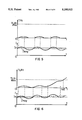
- FIG. 4 illustrates the variations, versus time, of TLR for a conventional long delay function, of the same type as in FIG. 1, when the value I representative of the current oscillates periodically around a mean value Imoy lower than the current threshold Is.
- the dissymmetry of the heating and cooling functions implies taking great account of the overshoots of the threshold Is by the value I, leading to tripping at a tripping time td1, when TLR reaches TLRmax, although the mean value of I remains constantly lower than the current threshold Is.
- TLR1 The same periodic oscillation of I around a mean value Imoy lower than the current threshold Is does not however lead to tripping if the variations of TLR1 are proportional to the difference between the square of I and the square of Is. Indeed, as represented in FIG. 5, the quantity TLR1, which can not be lower than a preset low value, zero in the figure, taking into account in the same way the values greater and lower than Is, returns to zero before the end of each variation period of I and can not reach the value TLR1max which would give rise to tripping. This variation law of TLR1 nevertheless gives rise to tripping (td2) if the mean value Imoy of the current exceeds the tripping threshold Is for a sufficiently long time (FIG. 6).
- the quantity TLR1 is combined with another quantity TLR2 representative of the thermal state of the circuit breaker.
- This quantity TLR2 has, like the quantity TLR of conventional long delay functions, a positive variation, preferably proportional to I 2 , to simulate heating, and a negative variation, preferably exponential, to simulate cooling.
- switching between the heating and cooling functions of the quantity TLR2 is not directly linked to the comparison of the value I with the current threshold (Is), but with the comparison of the quantity TLR1 to an intermediate heating threshold STLR1.
- FIG. 7 represents the variations versus time of TLR1 (curve c) and TLR2 (curve d) for various relative values of I and Is:
- I is less than Is, the quantities TLR1 and TLR2, nil at the outset, remain at zero.
- TLR1 then increases proportionally to I 2 -Is 2 .
- TLR1 remaining less than STRL1
- TLR2 remains at zero.
- TLR1 which continues to increase, reaches the threshold STLR1, and leads the quantity TLR2 to simulate overheating.
- TLR2 increases according to I 2 t.
- the quantity TLR1 has a maximum limit of a high level PTLR1. When it reaches this value, at the time t3, it remains equal to this value so long as I is greater than Is.
- I becomes slightly lower than Is again, and TLR1 decreases.
- I 2 -Is 2 being, in absolute value, slightly smaller after the time t4 than between the times t1 and t3, the decrease of TLR1 after the time t4 is less fast than its increase between the times t1 and t3.
- TLR1 remains greater than STLR1 and TLR2 continues to simulate overheating, and therefore to increase proportionally to I 2 .
- the value of I between t4 and t5 being lower than its value between t1 and t4, the increase of TLR2 is then less fast than before.
- TLR1 drops below STLR1, from t5, TLR2 simulates cooling and decreases exponentially.
- TLR1 At the time t6, I becomes greater than Is. TLR1 then increases quickly and reaches the threshold STLR1 at the time t7. Between t6 and t7, TLR2 continues to decrease exponentially.
- TLR2 increases very quickly up to the time t8 when I becomes smaller than Is again.
- TLR1 decreases proportionally to the difference I 2 -Is 1 , i.e. fairly quickly in the example represented in the figure, I then being much lower than Is. TLR1 remains greater than STLR1 up to the time t9. Between t8 and t9, TLR2 continues to increase, but less quickly than between t7 and t8 as I is much weaker.
- TLR2 starts to decrease exponentially again.
- TLR2 remains lower than a maximum value TLR2max, no tripping signal is emitted.
- the quantity TLR2 only simulates heating or cooling with a certain delay with respect to time when the value I becomes respectively greater or smaller than the current threshold Is.
- the time delay on heating is represented by tr1, between the times t1 and t2, and tr3 between the times t6 and t7, the time delay on cooling corresponding to tr2 between the times t4 and t5 and tr4 between the times t8 and t9.
- This inertia on heating and cooling depends on the level of the value I representative of the current with respect to the current threshold Is.
- the time delay tr3 on heating is much shorter than the time delay tr1 on heating corresponding to a smaller overshoot of the threshold Is by the value I from the time t1.
- a value representative of the current whose mean value is lower than the threshold during the time delay will not result in tripping.
- the inertia on heating of the quantity TLR2 resulting from the use of the quantity TLR1 prevents any increase of TLR2 so long as TLR1 has not exceeded the threshold STLR1.
- the choice of the threshold STLR1 enables the shape of the tripping curve to be adjusted.
- the threshold STLR1 should preferably be chosen equal to PTLR1/2, as represented in FIG. 7.
- FIGS. 5 and 6 apply to the variations of TLR1 according to the invention, if TLR1max is replaced by STLR1. In FIG.
- TLR1 increases continuously, and when TLR1 reaches the threshold STLR1, TLR2 starts simulating heating. If the latter continues for a sufficient length of time, TLR2 will reach TLR2max and give rise to tripping.
- FIG. 8 illustrates various tripping curves of a long delay function according to the invention.
- the tripping curve represented in FIG. 8 corresponds to the conventional long delay tripping curve represented by a in FIG. 3.
- the electronic processing unit 7 comprises a microprocessor and the long delay function is performed according to the flow chart represented in FIG. 9.
- TLR1 is recomputed (F2), then (F3) compared with the threshold STLR1. If TLR1 is greater than STLR1, the square of the value I is added to TLR2 (F4) and the new value TLR2 is compared with TLR2max (F5). If TLR2 is greater than TLR2max, a tripping order is produced (F6). If (F3) TLR1 is lower than STLR1, TLR2 is reduced according to an exponential function (F7). At the end of the cycle (F8), if TLR1 is less than zero, TLR1 is zero reset, and if TLR1 is greater than PTLR1, it is limited to this value for the next cycle. This limiting of TLR1 to high and low values could possibly be performed between stages F2 and F3.
- Variations of the value representative of the current around a mean value can have numerous causes.
- a value I representative of the rms value of the current obtained by sampling of the output signal from the detection means, raising to the square and integration over a preset integration period, results in a value I of this type being obtained, oscillating periodically around the actual rms value of the current as soon as the current frequency varies.
- a frequency of 50 Hz curve e
- the difference E is nil
- a frequency variation of 1 Hz results in a non-negligible difference, of nil mean value, varying sinusoidally with a period Tv of 0.5 s (curves f and g).
- This curve presents a succession of lobes, the maximum difference varying very greatly with the frequency according to the relative values of the sampling period, the integration period and the signal period.
- the maximum difference is nil when the integration period is an integer multiple of the signal half-period and increases to form intermediate lobes when it moves away from these values.
- the variation period Tv of the difference E is greater the smaller the maximum difference Emax, and in all cases the mean value of the difference E tends to zero.
- the invention described above by eliminating the influence of the variations of the value representative of the current around a mean value, enables the trip device to be rendered practically insensitive to numerization errors due to the choice of the integration period with respect to the mains frequency and, for preset sampling and integration periods, enables it to be rendered insensitive to mains frequency variations. All the intermediate lobes can be eliminated by implementing the invention under the sampling and integration conditions represented in FIG. 11.
- the signal is sampled in successive groups of 4 samples with a sampling period Te, the adjacent samples of two successive groups being separated by Te +Te/4.
- another embodiment consists in sampling the output signals from the detection means in successive groups of n samples, the sampling periods of two successive groups being different.
- a cycle of four groups of 64 samples can, for a mean sampling period Te, be performed as follows:
- the values of the sampling period (Te1, Te2; Te3, Te4) are distributed symmetrically with respect to a mean value (Te) of the sampling period.
- the different values of the sampling periods are chosen in such a way as to have maximum covering of the signal in the shortest possible time while remaining independent from the mains frequency.
- the number n of samples of a group is independent from the number of samples taken into account during an integration period Ti.
- the invention applies not only to a single-phase trip device, but also to a multipole trip device. It is then indispensable to separate processing of the currents of the different phases for collection of the values Ii, for example I1, I2, I3 and In for a trip device with three phases and neutral, representative of the current in the different phases and computation of associated quantities TLR1 Ii, as shown in FIG. 12 (stages F11 to F14 and F21 to F24). However, a single quantity TLR2 can be used.
- the quantities TLR1 Ii are compared to the threshold STLR1 (F30) and if at least one of them is greater than the threshold, TLR2 is increased by the square of the maximum value Iimax representative of the currents (F40) before being compared to TLR2max (F50), so as to produce a tripping signal (F60) if TLR2 is greater than TLR2max. If none of the quantities TLR1 Ii is greater than STLR1, the quantity TLR2 is decremented exponentially (F70).
Landscapes
- Physics & Mathematics (AREA)
- Electromagnetism (AREA)
- Emergency Protection Circuit Devices (AREA)
- Breakers (AREA)
- Pulse Circuits (AREA)
Applications Claiming Priority (2)
| Application Number | Priority Date | Filing Date | Title |
|---|---|---|---|
| FR9008527 | 1990-07-03 | ||
| FR9008527A FR2664442B1 (fr) | 1990-07-03 | 1990-07-03 | Declencheur electronique comportant une fonction long retard amelioree. |
Publications (1)
| Publication Number | Publication Date |
|---|---|
| US5195012A true US5195012A (en) | 1993-03-16 |
Family
ID=9398380
Family Applications (1)
| Application Number | Title | Priority Date | Filing Date |
|---|---|---|---|
| US07/719,186 Expired - Lifetime US5195012A (en) | 1990-07-03 | 1991-06-21 | Electronic trip device comprising an improved long delay function |
Country Status (9)
| Country | Link |
|---|---|
| US (1) | US5195012A (fr) |
| EP (1) | EP0465384B1 (fr) |
| JP (1) | JP3027237B2 (fr) |
| KR (1) | KR0180746B1 (fr) |
| CA (1) | CA2045043A1 (fr) |
| DE (1) | DE69114061T2 (fr) |
| ES (1) | ES2080280T3 (fr) |
| FR (1) | FR2664442B1 (fr) |
| MY (1) | MY106378A (fr) |
Cited By (6)
| Publication number | Priority date | Publication date | Assignee | Title |
|---|---|---|---|---|
| US6141202A (en) * | 1998-08-07 | 2000-10-31 | Daimlerchrysler Ag | Method and apparatus for triggering a fuse |
| US20010014068A1 (en) * | 2000-01-28 | 2001-08-16 | Meng-Huang Chu | Device and method for preventing excess current flowing into pick-up head of optical storage device |
| SG96689A1 (en) * | 2001-06-19 | 2003-06-16 | Schneider Electric Ind Sa | Electronic trip device comprising a capacitor for supply of a trip coil |
| US7421353B1 (en) | 2002-11-20 | 2008-09-02 | National Hybrid, Inc | Digital integration method |
| US20100045263A1 (en) * | 2006-12-18 | 2010-02-25 | Schneider Electric Industries Sas | Current measurement device with electrical isolation, electronic trip unit, and circuit breaker comprising one such device |
| US20100060261A1 (en) * | 2006-12-18 | 2010-03-11 | Schneider Electric Industries Sas | Measurement signal coupling device with electrical isolation and electrical equipment unit comprising one such device |
Families Citing this family (4)
| Publication number | Priority date | Publication date | Assignee | Title |
|---|---|---|---|---|
| US5763993A (en) * | 1994-04-01 | 1998-06-09 | Samsung Display Devices Co., Ltd. | Focusing electrode structure for a color cathode ray tube |
| DE102009027387B4 (de) * | 2009-07-01 | 2019-01-03 | Lisa Dräxlmaier GmbH | Vorrichtung und Verfahren zum Absichern einer elektrischen Leitung mit einem steuerbaren Schaltelement |
| US20240186784A1 (en) * | 2022-12-02 | 2024-06-06 | Hamilton Sundstrand Corporation | Residual overcurrent protection |
| DE102024205474A1 (de) * | 2024-06-13 | 2025-12-18 | Robert Bosch Gesellschaft mit beschränkter Haftung | System und Verfahren zum Verdrahtungsschutz |
Citations (3)
| Publication number | Priority date | Publication date | Assignee | Title |
|---|---|---|---|---|
| US4445183A (en) * | 1981-12-23 | 1984-04-24 | Rockwell International Corporation | Electrical switch |
| FR2540303A1 (fr) * | 1983-01-31 | 1984-08-03 | Gen Electric | Dispositif de protection i2t pour un composant electrique |
| US4717985A (en) * | 1985-02-25 | 1988-01-05 | Merlin Gerin S.A. | Circuit breaker with digitized solid-state trip unit with inverse time tripping function |
-
1990
- 1990-07-03 FR FR9008527A patent/FR2664442B1/fr not_active Expired - Fee Related
-
1991
- 1991-06-20 CA CA002045043A patent/CA2045043A1/fr not_active Abandoned
- 1991-06-21 US US07/719,186 patent/US5195012A/en not_active Expired - Lifetime
- 1991-06-25 ES ES91420209T patent/ES2080280T3/es not_active Expired - Lifetime
- 1991-06-25 EP EP91420209A patent/EP0465384B1/fr not_active Expired - Lifetime
- 1991-06-25 DE DE69114061T patent/DE69114061T2/de not_active Expired - Fee Related
- 1991-07-01 MY MYPI91001188A patent/MY106378A/en unknown
- 1991-07-02 KR KR1019910011211A patent/KR0180746B1/ko not_active Expired - Fee Related
- 1991-07-02 JP JP3188206A patent/JP3027237B2/ja not_active Expired - Fee Related
Patent Citations (3)
| Publication number | Priority date | Publication date | Assignee | Title |
|---|---|---|---|---|
| US4445183A (en) * | 1981-12-23 | 1984-04-24 | Rockwell International Corporation | Electrical switch |
| FR2540303A1 (fr) * | 1983-01-31 | 1984-08-03 | Gen Electric | Dispositif de protection i2t pour un composant electrique |
| US4717985A (en) * | 1985-02-25 | 1988-01-05 | Merlin Gerin S.A. | Circuit breaker with digitized solid-state trip unit with inverse time tripping function |
Cited By (9)
| Publication number | Priority date | Publication date | Assignee | Title |
|---|---|---|---|---|
| US6141202A (en) * | 1998-08-07 | 2000-10-31 | Daimlerchrysler Ag | Method and apparatus for triggering a fuse |
| US20010014068A1 (en) * | 2000-01-28 | 2001-08-16 | Meng-Huang Chu | Device and method for preventing excess current flowing into pick-up head of optical storage device |
| US7020061B2 (en) * | 2000-01-28 | 2006-03-28 | Via Technologies, Inc. | Device and method for preventing excess current flowing into pick-up head of optical storage device |
| SG96689A1 (en) * | 2001-06-19 | 2003-06-16 | Schneider Electric Ind Sa | Electronic trip device comprising a capacitor for supply of a trip coil |
| US7421353B1 (en) | 2002-11-20 | 2008-09-02 | National Hybrid, Inc | Digital integration method |
| US20100045263A1 (en) * | 2006-12-18 | 2010-02-25 | Schneider Electric Industries Sas | Current measurement device with electrical isolation, electronic trip unit, and circuit breaker comprising one such device |
| US20100060261A1 (en) * | 2006-12-18 | 2010-03-11 | Schneider Electric Industries Sas | Measurement signal coupling device with electrical isolation and electrical equipment unit comprising one such device |
| US8378663B2 (en) | 2006-12-18 | 2013-02-19 | Schneider Electric Insustries SAS | Current measurement signal device with electrical isolation, electronic trip unit, and circuit breaker comprising one such device |
| US8390270B2 (en) * | 2006-12-18 | 2013-03-05 | Schneider Electric Industries Sas | Measurement signal coupling device with electrical isolation and electrical equipment unit comprising one such device |
Also Published As
| Publication number | Publication date |
|---|---|
| MY106378A (en) | 1995-05-30 |
| FR2664442B1 (fr) | 1996-04-26 |
| EP0465384B1 (fr) | 1995-10-25 |
| JP3027237B2 (ja) | 2000-03-27 |
| EP0465384A1 (fr) | 1992-01-08 |
| CA2045043A1 (fr) | 1992-01-04 |
| ES2080280T3 (es) | 1996-02-01 |
| KR920003357A (ko) | 1992-02-29 |
| JPH04229014A (ja) | 1992-08-18 |
| DE69114061T2 (de) | 1996-05-09 |
| DE69114061D1 (de) | 1995-11-30 |
| FR2664442A1 (fr) | 1992-01-10 |
| KR0180746B1 (ko) | 1999-05-15 |
Similar Documents
| Publication | Publication Date | Title |
|---|---|---|
| JP2510508B2 (ja) | 遮断器のデジタル固体引外し装置 | |
| US4710845A (en) | Circuit breaker with solid-state trip unit with sampling and latching at the last signal peak | |
| US4689712A (en) | Circuit breaker with solid-state trip unit with a digital processing system shunted by an analog processing system | |
| US4682264A (en) | Circuit breaker with digital solid-state trip unit fitted with a calibration circuit | |
| US4589052A (en) | Digital I2 T pickup, time bands and timing control circuits for static trip circuit breakers | |
| US5115371A (en) | Circuit breaker comprising an electronic trip device | |
| US5195012A (en) | Electronic trip device comprising an improved long delay function | |
| JPS61240818A (ja) | 遮断器のデジタル固体引外し装置 | |
| JPH04255414A (ja) | 過負荷電流保安装置 | |
| US4571659A (en) | Static overcurrent trip device to operate a circuit breaker in response of fault conditions in an alternating current net system | |
| US3946281A (en) | Overcurrent protection system with variable inverse-time characteristic | |
| US6040689A (en) | Current sensing method and apparatus | |
| EP0300078B1 (fr) | Détecteur de surcharge et disjoncteur de puissance | |
| US3467890A (en) | Electrical circuit protection devices utilizing capacitor discharge | |
| CA1059608A (fr) | Relai statique de surintensite | |
| US3968410A (en) | Static overcurrent relays | |
| US4208688A (en) | Multipole ground fault circuit interrupter with trip level adjustment | |
| US5208720A (en) | Electronic trip device with short delay function | |
| JPH0884431A (ja) | 電流信号の補正方法およびその装置 | |
| US4428021A (en) | Current monitoring apparatus | |
| JP2506477B2 (ja) | 過電流検出装置 | |
| RU2015624C1 (ru) | Система наружного освещения | |
| JP2567439B2 (ja) | 過電流検出装置 | |
| SU748644A1 (ru) | Устройство дл защиты потребител от пропадани фазы трехфазной сети | |
| JP2994067B2 (ja) | ディジタル形周波数継電器 |
Legal Events
| Date | Code | Title | Description |
|---|---|---|---|
| AS | Assignment |
Owner name: MERLIN GERIN Free format text: LICENSE;ASSIGNOR:TRIPODI, PAUL;REEL/FRAME:005986/0052 Effective date: 19920113 |
|
| FEPP | Fee payment procedure |
Free format text: PAYOR NUMBER ASSIGNED (ORIGINAL EVENT CODE: ASPN); ENTITY STATUS OF PATENT OWNER: LARGE ENTITY |
|
| STCF | Information on status: patent grant |
Free format text: PATENTED CASE |
|
| FPAY | Fee payment |
Year of fee payment: 4 |
|
| FPAY | Fee payment |
Year of fee payment: 8 |
|
| FPAY | Fee payment |
Year of fee payment: 12 |