US5211162A - Apparatus and method for massaging the back utilizing pneumatic cushions - Google Patents
Apparatus and method for massaging the back utilizing pneumatic cushions Download PDFInfo
- Publication number
- US5211162A US5211162A US07/727,666 US72766691A US5211162A US 5211162 A US5211162 A US 5211162A US 72766691 A US72766691 A US 72766691A US 5211162 A US5211162 A US 5211162A
- Authority
- US
- United States
- Prior art keywords
- chamber
- pad
- chambers
- sectional area
- outer portions
- Prior art date
- Legal status (The legal status is an assumption and is not a legal conclusion. Google has not performed a legal analysis and makes no representation as to the accuracy of the status listed.)
- Expired - Fee Related
Links
- 238000000034 method Methods 0.000 title claims abstract description 28
- 210000000115 thoracic cavity Anatomy 0.000 claims abstract description 52
- 239000011800 void material Substances 0.000 claims abstract description 19
- 210000004872 soft tissue Anatomy 0.000 claims abstract description 16
- 230000001105 regulatory effect Effects 0.000 claims 3
- 230000000977 initiatory effect Effects 0.000 claims 2
- 238000002560 therapeutic procedure Methods 0.000 description 16
- 238000012163 sequencing technique Methods 0.000 description 10
- 238000010168 coupling process Methods 0.000 description 9
- 238000005859 coupling reaction Methods 0.000 description 9
- 210000003195 fascia Anatomy 0.000 description 9
- 230000008878 coupling Effects 0.000 description 5
- 230000033001 locomotion Effects 0.000 description 5
- 210000003205 muscle Anatomy 0.000 description 4
- 238000007789 sealing Methods 0.000 description 4
- 208000002193 Pain Diseases 0.000 description 3
- 238000010276 construction Methods 0.000 description 3
- 238000010586 diagram Methods 0.000 description 3
- 208000027418 Wounds and injury Diseases 0.000 description 2
- 230000006378 damage Effects 0.000 description 2
- 230000000694 effects Effects 0.000 description 2
- 239000011521 glass Substances 0.000 description 2
- 208000014674 injury Diseases 0.000 description 2
- 230000000007 visual effect Effects 0.000 description 2
- LQIAZOCLNBBZQK-UHFFFAOYSA-N 1-(1,2-Diphosphanylethyl)pyrrolidin-2-one Chemical compound PCC(P)N1CCCC1=O LQIAZOCLNBBZQK-UHFFFAOYSA-N 0.000 description 1
- 206010063493 Premature ageing Diseases 0.000 description 1
- 208000032038 Premature aging Diseases 0.000 description 1
- 230000002745 absorbent Effects 0.000 description 1
- 239000002250 absorbent Substances 0.000 description 1
- 230000032683 aging Effects 0.000 description 1
- 210000003484 anatomy Anatomy 0.000 description 1
- 230000037396 body weight Effects 0.000 description 1
- 210000000988 bone and bone Anatomy 0.000 description 1
- 230000003247 decreasing effect Effects 0.000 description 1
- 238000011161 development Methods 0.000 description 1
- 230000018109 developmental process Effects 0.000 description 1
- 201000010099 disease Diseases 0.000 description 1
- 208000037265 diseases, disorders, signs and symptoms Diseases 0.000 description 1
- 229940079593 drug Drugs 0.000 description 1
- 239000003814 drug Substances 0.000 description 1
- -1 flexible Substances 0.000 description 1
- 230000007794 irritation Effects 0.000 description 1
- 210000003041 ligament Anatomy 0.000 description 1
- 238000004519 manufacturing process Methods 0.000 description 1
- 239000000463 material Substances 0.000 description 1
- 230000001483 mobilizing effect Effects 0.000 description 1
- 238000012986 modification Methods 0.000 description 1
- 230000004048 modification Effects 0.000 description 1
- 231100000862 numbness Toxicity 0.000 description 1
- 230000000399 orthopedic effect Effects 0.000 description 1
- 229920003023 plastic Polymers 0.000 description 1
- 239000004033 plastic Substances 0.000 description 1
- 229920002635 polyurethane Polymers 0.000 description 1
- 239000004814 polyurethane Substances 0.000 description 1
- 230000000630 rising effect Effects 0.000 description 1
- 238000005096 rolling process Methods 0.000 description 1
- 230000035882 stress Effects 0.000 description 1
- 238000001356 surgical procedure Methods 0.000 description 1
- 208000024891 symptom Diseases 0.000 description 1
- 230000001225 therapeutic effect Effects 0.000 description 1
Images



Classifications
-
- A—HUMAN NECESSITIES
- A61—MEDICAL OR VETERINARY SCIENCE; HYGIENE
- A61H—PHYSICAL THERAPY APPARATUS, e.g. DEVICES FOR LOCATING OR STIMULATING REFLEX POINTS IN THE BODY; ARTIFICIAL RESPIRATION; MASSAGE; BATHING DEVICES FOR SPECIAL THERAPEUTIC OR HYGIENIC PURPOSES OR SPECIFIC PARTS OF THE BODY
- A61H9/00—Pneumatic or hydraulic massage
- A61H9/005—Pneumatic massage
- A61H9/0078—Pneumatic massage with intermittent or alternately inflated bladders or cuffs
-
- A—HUMAN NECESSITIES
- A61—MEDICAL OR VETERINARY SCIENCE; HYGIENE
- A61H—PHYSICAL THERAPY APPARATUS, e.g. DEVICES FOR LOCATING OR STIMULATING REFLEX POINTS IN THE BODY; ARTIFICIAL RESPIRATION; MASSAGE; BATHING DEVICES FOR SPECIAL THERAPEUTIC OR HYGIENIC PURPOSES OR SPECIFIC PARTS OF THE BODY
- A61H2201/00—Characteristics of apparatus not provided for in the preceding codes
- A61H2201/01—Constructive details
- A61H2201/0119—Support for the device
- A61H2201/0134—Cushion or similar support
-
- A—HUMAN NECESSITIES
- A61—MEDICAL OR VETERINARY SCIENCE; HYGIENE
- A61H—PHYSICAL THERAPY APPARATUS, e.g. DEVICES FOR LOCATING OR STIMULATING REFLEX POINTS IN THE BODY; ARTIFICIAL RESPIRATION; MASSAGE; BATHING DEVICES FOR SPECIAL THERAPEUTIC OR HYGIENIC PURPOSES OR SPECIFIC PARTS OF THE BODY
- A61H2201/00—Characteristics of apparatus not provided for in the preceding codes
- A61H2201/16—Physical interface with patient
- A61H2201/1602—Physical interface with patient kind of interface, e.g. head rest, knee support or lumbar support
- A61H2201/1623—Back
-
- A—HUMAN NECESSITIES
- A61—MEDICAL OR VETERINARY SCIENCE; HYGIENE
- A61H—PHYSICAL THERAPY APPARATUS, e.g. DEVICES FOR LOCATING OR STIMULATING REFLEX POINTS IN THE BODY; ARTIFICIAL RESPIRATION; MASSAGE; BATHING DEVICES FOR SPECIAL THERAPEUTIC OR HYGIENIC PURPOSES OR SPECIFIC PARTS OF THE BODY
- A61H2205/00—Devices for specific parts of the body
- A61H2205/08—Trunk
- A61H2205/081—Back
Definitions
- This invention is directed to therapy apparatus and a method for massaging a patient's back. More particularly, the apparatus and method relate to the massaging of portions of a patient's back in a sequential manner by a pad having a plurality of adjacent inflatable and deflatable chambers to mobilize the spine and massage, stretch, and relax the musculature and soft tissue. This allows the spine to realign, thereby decreasing pain and increasing mobility and range of motion.
- the back consists of a column of bones called vertebrae, which are separated by discs that act as cushions and are held together by muscles and ligaments.
- a normal healthy back has three natural curves, the upper cervical curve, the thoracic curve and the lower lumbar curve. When these three curves are in normal alignment, a person's body weight is evenly distributed throughout the vertebrae and discs, and when the muscle groups of the back are strong and flexible the person may move freely and without effort.
- Natural aging, premature aging, misuse, or injury give rise to certain spinal problems which cause a variety of symptoms, such as stiffness, pain, tingling and numbness. More serious back problems may require corrective surgery, but the majority of back problems respond favorably to non-surgical therapy. Many back problems may be healed by a combination of rest, modalities, medication, or bracing.
- U.S. Pat. No. 4,231,355 to Katsumasa Hara discloses an air device for massaging a body or body portion by means of a pad on a mat which holds the whole body or by means of a shaped article wrapped about a body portion.
- the pad/mat and the shaped articles are formed with a plurality of adjacent air inflatable bags which may be provided with their own inlet and exhaust ports for compressed air.
- U.S. Pat. No. 4,688,556 to Moreau A. Keller, Jr. is directed to a spinal massage and exercise device comprising one or more yielding oblate spheroids rotatably held in a support frame.
- the user of the device places his or her spine on the spheroids and propels the device with his or her legs to move the device and massage the spine.
- U.S. Pat. No. 3,826,249 to Arthur L. Lee, et al.; U.S. Pat. No. 4,013,069 to James H. Hasty; U.S. Pat. No. 4,396,010 to Edward J. Arkans; U.S. Pat. No. 4,480,599 to Thomas A. Mummert; U.S. Pat. No. 4,762,121 to Izhar Shienfeld; U.S. Pat. No. 4,793,328 to Mark Kolstedt; and U.S. Pat. No. 4,865,020 to Horace Bullard are directed to apparatus and/or a method for the sequential application of pressure to a portion of the body.
- the therapy apparatus comprises a pad, which includes a plurality of adjacent inflatable chambers connected to a sequential pressure device that includes a pneumatic system and a control system.
- the pad chambers extend transverse to the pad length and each is connected to the pneumatic system.
- the control system regulates the flow of compressed air from the pneumatic system to the pad chambers in a manner to sequentially inflate one or more chambers of the pad in a cyclical wave motion from pad bottom to top.
- the pad has a length to extend from bottom to top through the lumbar, thoracic and cervical portions of the spine of a patient.
- the lengths of the pad chambers extend transverse to the length of the pad.
- Two adjacent chambers in the lower section of the pad have approximately the same transverse cross sectional area for about their lengths. When inflated these two chambers assume a flattened cylindrical form for their lengths.
- In the upper section of the pad are a plurality of adjacent chambers, several of which have a right portion, a left portion, and a narrowed intermediate portion.
- the right and left portions of each such chamber have about the same transverse cross-sectional area and each intermediate portion narrows from the right and left portions toward the chamber's center to form an intermediate portion with a narrow center passage connecting right and left chamber portions.
- the narrowed intermediate portion of each such chamber creates a depression or valley, most apparent in a vertical plane, and a dead area on at least one side of the intermediate portion of such chamber passage, most apparent in the horizontal plane.
- the method of this invention utilizes the above described apparatus to mobilize the spine and massage, stretch, and relax the musculature and soft tissues of a user's back in a sequential manner from pad bottom to top for a selected time period.
- the user is placed in a supine position on the apparatus pad, with the user's spinal column extending along the longitudinal centerline of the pad.
- the two adjacent chambers of the pad lower section which each have the same transverse cross-sectional area for its length, are positioned to extend across the patient's back beneath the spinal column lumbar vertebrae.
- the adjacent chambers of the pad upper section are positioned to extend at least partially across the patient's back, with the intermediate portions thereof beneath the spinal column thoracic and cervical vertebrae.
- the sequential pressure device control system is activated to select the manner in which the chambers are to be sequenced, the time of inflation for each chamber, the total time for the cycles of sequencing, the air compressor of the pneumatic system is started, and the operating pressure for the chamber is selected.
- Each of the chambers is inflated and deflated in a sequential manner from pad bottom to top for a single cycle and the cycle repeated for the preselected time of operation.
- Each of the chambers of the pad lower section is sequentially inflated to contact and exert pressure upwardly across the user's back through the lumbar area thereof and raise that portion of the back, including the lumbar vertebrae, for the preselected time and then permitted to deflate.
- Each of the chambers of the pad upper section is sequentially inflated and the right and left portions expanded to contact and exert pressure upwardly against the patient's back in areas spaced from the spinal column and through the thoracic area thereof.
- the narrowed intermediate portion of each such chamber extends beneath the thoracic area of the spinal column with little, if any, contact with the thoracic vertebrae by virtue of the depression and dead areas formed by the intermediate portion.
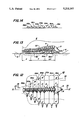
- FIG. 1 is a perspective view of the trunk of a patient positioned on a treatment table for treatment by the therapy apparatus of this invention.
- FIG. 2 is a plan view of the top sheet of the inflatable-deflatable therapy pad, which is in a deflated condition, of the apparatus of this invention.
- FIG. 3 is a schematic diagram of an embodiment of the apparatus of this invention showing the manner in which the sequential pressure device comprising the pneumatic system and the control system operates in conjunction with the inflatable-deflatable therapy pad.
- FIG. 4 is a plan view of the therapy pad of this invention in the inflated condition.
- FIG. 5 is an enlarged sectional view of the therapy pad taken along the line 5--5 of FIG. 4.
- FIG. 6 is an enlarged sectional view of the therapy pad taken along the line 6--6 of FIG. 4.
- FIG. 7 is an enlarged sectional view of one of the chambers of the therapy pad taken along the line 7--7 of FIG. 4.
- FIG. 8 is an enlarged sectional view of another of the chambers of the therapy pad taken along the line 8--8 of FIG. 4.
- FIGS. 9-11 are charts showing the inflation-deflation intervals of the chambers of the pad of this invention, for a single cycle of the operation of the pad for one-chamber, two-chamber and three chamber sequency.
- FIG. 12 is a plan view of the therapy pad of this invention with a schematic rendition of a patient's torso, partially in phantom, positioned on the pad, which is in the deflated condition, and showing the patient's spine.
- FIG. 13 is a cross-sectional view of the pad and torso of FIG. 12 taken along the line 13--13 of FIG. 12 and showing two chambers inflated and the remainder of the chambers deflated.
- FIG. 14 is a cross-sectional view only of the therapy pad of this invention taken along the line 14-14 of FIG. 12 with all of the chambers inflated.
- FIG. 15 is a schematic cross-section through the lumbar portion of a patient's torso showing the manner in which a pad chamber extending through that area contacts the surface of the back.
- FIG. 16 is a schematic cross-section through the thoracic portion of a patient's torso showing the manner in which a pad chamber extending through that area contacts the surface of the back.
- Apparatus 10 comprises sequential pressure device 11, including cabinet 12 in which are mounted pneumatic system 15 and control system 30, both shown in the schematic diagram of FIG. 3, and flat pad 40 positioned on treatment table 9 beneath trunk 2 of patient 1.
- pad 40 comprises flat top sheet 41 and flat bottom sheet 42, which in a deflated condition is beneath and in contact with the underside of top sheet 41
- Top sheet 41 and bottom sheet 42 are substantially identical in size and shape and made from non-absorbent, flexible, plastic or rubberized material, e.g. polyurethane sheeting, which easily can be cleaned and maintained in a sanitary condition.
- Sheets 41 and 42 are laid out in substantially the same manner, and the description, including numbers and letters, for top sheet 41 applies equally to bottom sheet 42.
- sheet 41 has seams 43-49 which are spaced transverse to longitudinal center line X-X' to form sections 51-58, respectively.
- Section 51 is at the bottom of sheet 41 and section 58 at the top.
- Each section has a lower edge c, upper edge d, right end portion e and left end portion f, which includes tube extension portion g.
- Sections 51-54 are of about the same length L-1 of about 24 inches.
- Section 55 has a length L-2 of about 22 inches
- section 56 has a length L-3 of about 18 inches
- section 57 has a length L-4 of about 11 inches
- section 58 has a length L-5 of about 7 inches, each of sections 55-58 being progressively shorter than the adjacent lower section.
- Sections 52 and 53 are the widest with a width w-1 of about 41/4 inches; section 54 has a width w-2 of about 31/2 inches, slightly narrower than width w-1; section 55 has a width w-3 of about 31/4 inches, slightly narrower than width w-2; lower section 51 and section 56 have a width w-4 of about 3 inches, slightly narrower than width w-3; section 57 has a width w-5 of about 23/4 inches, slightly narrower than width w-4; and top section 58 has a width w-6 of about 21/2 inches, slightly narrower than width w-5.
- the widths of sections 51-58 should not differ by more than about ⁇ 1/8 inch from those stated above.
- top sheet 41 is symmetrical about longitudinal center line X-X'.
- arcs J and K are arcs J and K, respectively, each having a chord length L-10 of about 53/4 inches.
- arcs M and N are arcs M and N, respectively, each having a chord length L-11 of about 43/4 inches.
- chord lengths of L-10 and L-11 should not differ by more than about ⁇ 1/8 inch and the distances D-1 and D-2 should not differ by more than about ⁇ 1/16, inch from those stated above.
- section 51 between lower edge c and arc J and between upper edge d and arc K, and of sections 54-56 between lower edge c and arc M and between upper edge d and arc N and of section 57 between lower edge c and arc M arc shaded in FIG. 2.
- Each two shaded areas for sections 51 have the same dimensions and area.
- Each of the two shaded areas for sections 54-56 and the one for section 57 have the same dimensions and area.
- the overall length of top sheet 41 in a deflated condition is N-1, about 261/2 inches.
- the distance between arcs J and K of section 51 is d-1, about 11/8 inches; between arcs M and N of section 54 is d-2, about 1 inch; between arcs M and N of section 55 is d-3, about 3/4 of an inch; between arcs M and N of section 56 is d-4, about 1/2 of an inch; and between arc M and upper edge d of section 57 is d-5, about 11/2 inches.
- the arcs formed in sections 51, and 54-57 divide each such section into a left portion A, right portion B, and narrower intermediate portion I, with left portion A and right portion B of each section being about the same length and width.
- Top sheet 41 and bottom sheet 42 are heat sealed along seams 43-49, along lower edge c of section 51, along upper edge d of section 58, along right end portions e, along left end portions f, and along tube extensions g, except for their ends which form a passage or opening, not identified, in all of chamber sections 51-58.
- the heat scaling is shown by the double lines in FIG. 2.
- a quick-lock adaptor half 50 extends into each passage or opening, not identified, between top and bottom sheet tube extensions g, which are sealed along their edges.
- FIG. 3 is a schematic diagram of the sequential pressure device 11 as used in conjunction with the operation of pad 40 and which comprises pneumatic system 15 and control system 30.
- Pneumatic system 15 includes air inlet line 16, air compressor 17, having filters, not identified, at its inlet and discharge ends, compressed air manifold 18 which connects with compressed air feed lines 21-28 that each terminates in multi-tube quick-coupling half 19.
- interconnecting with quick-coupling half 19 is multi-tube quick-coupling half 19A to which are connected compressed air feed lines 21A-28A that are extensions of feed lines 21-28, respectively.
- a quick-lock adaptor half 50A which interconnects with a quick-lock adaptor half 50 associated with one of the end portions g of one of sections 51-58, respectively, of top and bottom sheets 41 and 42, respectively, of pad 40.
- Compressor 17 is a rotary vane air compressor, rated at 1.2 C.F.M. at 5 p.s.i. and manufactured by Gast Manufacturing Corporation of Benton Harbor, Mich.
- Multitube quick-coupling halves 50-50A are of a type manufactured by Burron Medical Corporation of Bethlehem, Pa.
- Solenoid valves 21V-28V are well known to those skilled in the art and each includes a solenoid and a two-position, three-way valve. The two positions are open or close, and the valve has three ports, inlet, discharge, and exhaust.
- Control system 30 mounted in cabinet 12 with display panel 12A comprises a user interface device 31, e.g. a keypad which interconnects through line 32 with electronic control sub-system 33.
- Keypad 31 is a fourteen-button keypad with number buttons 0-9, and buttons for pause, start, clear, and stop.
- Electronic control sub-section 33 includes a printed circuit board, microprocessor/controller, and related elements, not identified, all well known to those skilled in the control art, and interconnects through line 34 with visual display screen 35, through line 36 with compressor 17, and through line 37 and branch lines 38A-38H with solenoid valves 21V-28V, respectively.
- Manual on-off rocker-switch 39 connected to a source of power, not shown, provides power to sequential pressure device 11.
- compressed air from air compressor 17 passes through manifold 18, in a manner hereinafter described, through feed lines 21-28, sequentially through valves 21V-28V, quick coupling 19/19A, feed lines 21A-28A and adaptor 50/50A, through tube extensions g and between sections 51-58 of pad top sheet 41 and bottom sheet 42.
- the compressed air separates sections 51-58 of bottom sheet 41 from sections 51-58 of pad top sheet 42 inflating chambers 51A-58A of pad 40.
- pad 40 is shown, for illustrative purposes only, with all chambers 51A-58A inflated. With all chambers inflated pad 40 has a length N-2 of about 201/2 inches.
- Chambers 52A, 53A and 58A resemble slightly flattened tubes.
- FIG. 7 shows a longitudinal cross section 53A.
- Chambers 52A and 53A have about the same length L'-1, about 221/2 inches; about the same width W-1, about 3 inches; about the same height H-1, about 25/8 inches; about the same transverse cross-sectional area, i.e. about 6.2 square inches; and are the largest chambers of pad 40.
- the length L'-1 is wider than the width of the back of almost all patients.
- Chamber 58A has a length L'-5, about 61/4 inches, a width W-6, about 17/8 inches; a height H-6, about 13/4 inches, a transverse cross sectional area of about 2.6 square inches, and is the smallest chamber of pad 40.
- Chambers 51A and 54A-57A have a different configuration than that of chambers 52A, 53A and 58A.
- Chambers 51A and 54A-57A each has a left portion A', a right portion B' and an intermediate portion I'.
- Left portion A' and right portion B' of each of chambers 51A and 54A-57A are generally of the same size, i.e. length, width, and height. However, the dimensions of chambers 51A and 54A-57A are somewhat different.
- Chamber 51A has a length L'-1 of about 221/2 inches and for left portion A' and right portion B' a width W-4 of about 21/4 inches, a height H-4 of about 21/8 inches and a transverse cross sectional area of about 4.52 square inches.
- Chamber 54A has a length L'-1 of about 221/2 inches and for left portion A' and right portion B' a width W-2 of about 25/8 inches, a height H-2 of about 23/8 inches, and a transverse cross-sectional area of about 4.91 square inches.
- Chamber 55A has a length L'-2 of about 21 inches, and for left portion A' and right portion B' a width W-3 of about 23/8 inches, a height H-3 of about 21/8 and a transverse cross-sectional area of about 3.98 square inches.
- Chamber 56A has a length L'-3 of about 16 inches and for left portion A' and right portion B' a width W-4 of about 21/4 inches, a height H-4 of about 21/8 inches, and a transverse cross-sectional area of about 4.52 square inches.
- Chamber 57A has a length L'-4 of about 10 inches and for left portion A' and right portion B' a width W-5 of about 2 inches, a height H-5 of about 17/8 inches, and a transverse cross-sectional area of about 2.45 square inches.
- the width and height of left portion A' and right portion B' of each of chambers 51A and 54A-57A are the dimensions through the transverse cross sections thereof, which are about equal.
- the intermediate portion I' of each of chambers 51A and 54A-57A is narrower at its center and in a horizontal plane extending through the longitudinal center line of each such chamber, than its adjacent left portion A' and right portion B' by virtue of the heat sealing of arc M of chamber 57A, the two arcs M and N of chambers 54A-56A, and the two arcs J and K of chamber 51A.
- the area between heat sealed bottom edge c and arc M is a flat, dead area and will not inflate.
- each of chambers 51A and 54A-57A narrows or tapers, as best shown for chambers 54A-57A in FIG. 4 and better shown for chamber 51A in FIG. 8.
- the narrowing or tapering begins at inner ends A'-1 and B'-1 of each chamber portion A' and B', respectively, and extends toward the chamber center lying on pad longitudinal center line X-X'.
- intermediate portion I' has a length I'L of about 8 inches between inner end A'-1 of chamber portion A' and inner end B'-1 of chamber portion B'.
- intermediate portion I' has a length I'L of about 7 inches between inner end A'-1 of chamber portion A' and inner end B'-1 of chamber portion B'.
- intermediate portion I' has a length I'L, not identified, of about 6 inches;
- intermediate portion I' has a length I'L, not identified, of about 51/2 inches;
- intermediate portion I' has a length I'L, not identified, of about 5 inches.
- each of chambers 51A and 54A-56A imparts an hour-glass configuration to each such chamber, i.e. larger at both ends and narrower in the center.
- the sealing of arcs M of chamber 57A causes it to narrow only along the upper edge D.
- each of chambers 51A and 54A-57A has a small passage or opening through the center of its intermediate portion I' of generally transverse oval, almost circular, shape.
- Chamber 51A has passage 51Z with a width of about 3/4 inch and a transverse cross-sectional area of about 0.44 square inch.
- Chamber 54A has passage 54Z with a width of about 7/8 inch and a transverse cross-sectional area of about 0.60 square inch.
- Chamber 55A has passage 55Z with a width of about 5/8 inch and a transverse cross-sectional area of about 0.31 square inch.
- Chamber 56A has passage 56Z with a width of about 1/2 inch and a transverse cross-sectional area of about 0.20 square inch.
- Chamber 57A has passage 57Z with a width of about 11/8 inch and a transverse cross sectional area of about 1.0 square inch.
- each of their longitudinal centerlines, not identified, extends centrally through left portion A', right portion B' and intermediate portion I', including passages 51Z, 54Z, 55Z, and 56Z, respectively.
- the longitudinal centerline through left portion A' and right portion B' is offset horizontally from the longitudinal centerline through intermediate portion I' including passage 57Z.
- Each of passages 51Z, 54Z-57Z is of a size to effect about simultaneous inflation of the left portion A' and right portion B' of its respective chamber to ensure that both portions inflate in about the same time period.
- a further result of the hour-glass configuration of intermediate portion I' of chambers 51A and chambers 54A-56A is the creation of a void or depression D about each such intermediate portion I' except through a horizontal plane extending through the longitudinal centerline of each such chamber in which top sheet 41 and bottom sheet 42 are sealed to form dead spaces on each side of the intermediate portion I.
- FIG. 8 which is a vertical sectional view through the longitudinal centerline of chamber 51A, void or depression D is shown shaded above and below intermediate portion I'. At the center of I', depression or void D has a depth Dd of about 3/4 of an inch.
- FIG. 6 which is a vertical sectional view through the longitudinal centerline of pad 40, depression or void D is shown shaded to illustrate that it extends for almost 360° about the periphery of intermediate passage 51Z.
- the heat sealing of top pad 41 and bottom pad 42 along lower edge c and arc J and upper edge d and arc K form dead areas on each side of a major portion of chamber intermediate portion I', as best shown in FIG. 4.
- FIG. 8 which is a vertical sectional view through the longitudinal centerline of chamber 51A, void or depression D is shown shaded above and below intermediate portion I'. At the center of I', depression or void D has a depth Dd of about 3/4 of an inch.
- FIG. 6 which is a vertical sectional view through the longitudinal center
- each of chambers 54A, 55A and 56A has void or depression D about openings 54Z, 55Z, and 56Z, respectively.
- Depth Dd for both voids or depressions D of chambers 54A, 55A and 56A is about 1 inch.
- depth Dd for void or depression D is measured in a vertical plane extending through the longitudinal centerline of passage 57Z at the center of the chamber to horizontal planes extending tangentially of the top center and bottom center of chamber 57A.
- therapy apparatus 10 is initiated by a user moving rocker switch 39, which is located on display panel 12A of cabinet 12, to the on-position.
- the user is guided through a series of displays or options programmed into the electronic control sub-system 33 of sequential pressure device 11 to enter all desired information or parameters before operation of pad 40 is begun.
- the menu or options appear on visual display screen 35.
- Menu 1 offers "back" appliance option only, but others may be added.
- Menu 2 enters "chamber” options, i.e. single-chamber, double-chamber, triple-chamber, which corresponds to the number of chambers to be inflated during a cycle of the sequential inflation of chambers 51A-58A of pad 40.
- each of chambers 51A-58A is inflated by itself sequentially, i.e. 51A, 52A, 53A etc. until the cycle through chamber 58A is completed.
- double or triple-chamber option is elected the chambers are sequentially inflated in a staggered manner as hereinafter described.
- Menu 3 offers an option of the time or duration that each chamber is, or chambers are, to be inflated, i.e. fast, e.g. 3 seconds/chamber, medium, e.g. 6 seconds/chamber, or slow, e.g. 9 seconds/chamber.
- Menu 4 permits a choice of operation time in minutes for the number of cycles or period that sequential inflation of pad chambers 51A-58A is to occur.
- Knob 14A is turned to set the operating pressure of the compressed air to be fed to chambers 51A-58A, at a preferred range of between 3 to 5 p.s.i., maximum 8 p.s.i. depending upon several variables, including the weight of patient 1.
- the sequential inflation of chambers 51A-58A creates the appearance of a wave moving through pad 40.
- the moving wave may be described as having four attributes, speed, width, amplitude, and direction.
- the speed of the wave relates to how fast it travels through pad 40 and is a function of the time period that each chamber is, or double chambers or triple chambers are, inflated. As mentioned above, for menu 3, three speeds are available, 3 seconds per chamber, 6 seconds per chamber or chambers, or 9 seconds per chamber or chambers.
- the width of the wave relates to the maximum number of chambers inflated during a sequence. This relates to the choice of menu 2, i.e., single chamber, double-chamber, or triple chamber.
- the amplitude of the wave relates to the maximum air pressure to be fed to a particular chamber. This variable is established by rotation of knob 4A on panel 12A. Safety relief valve 13 and the capabilities of compressor 17 prevent the system pressure from exceeding 8 p.s.i.
- the sequencing of inflation of chambers 51A-58A and the movement of the wave through pad 40 progresses from bottom chamber 51A to top chamber 58A then repeats the sequence from bottom to top until the operating time or time for the number of cycles and total period of sequencing desired is completed.
- switch 39 To initiate operation of pad 40, switch 39 is moved to the "on" position, the appropriate buttons of keypad 31a of sequential pressure device 11 are pressed and the desired air pressure is selected by turning knob 14A. For example, a pressure of about 5 p.s.i. is selected, then single-chamber sequencing is selected for menu 2, medium--6 seconds/chamber inflation for menu 3, 8 minute operation time, i.e. 10 cycles for menu 4, and the start button is pressed to initiate operation. Compressor 17 starts and feeds air at a pressure of about 5 p.s.i. through manifold 18 and feed lines 21-28 to solenoid valves 21V-28V.
- Valve 21V is moved to the open-port position by the programming of electronic control sub-system 33 and compressed air rapidly passes through the open-port of valve 21V, the continuation of line 21, multi-tube coupling 19/19A, line 21A, quick-lock adaptor 50/50A into chamber 51A and inflates it.
- Valve 21V remains in the open-port position for 6 seconds then moves to the closed-port position at which time the compressed air from chamber 51A slowly exhausts through the valve exhaust port to the atmosphere permitting chamber 51A to slowly deflate.
- valve 21V At the moment valve 21V is moved to the closed-port position by electronic control sub-system 33, it also signals solenoid valve 22V to move to the open-port position and compressed air rapidly passes through the open-port of valve 22V, the continuation of line 22, multi-tube coupling 19/19A, line 22A, quick-lock adaptor 50/50A into chamber 52A, and inflates it. Chamber 52A is inflated before chamber 51A is completely deflated. Valve 22V remains in the open-port position for 6 seconds then moves to the closed-port position at which time the compressed air from chamber 52A slowly passes through the valve exhaust port to the atmosphere permitting chamber 52A to slowly deflate.
- valves 23V-28V is caused to operate in an identical manner for 6 seconds to cause chambers 53A-58A to sequentially, rapidly inflate and then slowly deflate until one cycle of operation of pad 40 is completed.
- the sequential inflation and deflation of chambers 51A-58A gives the appearance of a wave moving from the bottom to the top of pad 40.
- the sequential inflation-deflation of chambers 51A-58A continues through nine more cycles until the operating time of 8 minutes, i.e. 10 cycles is completed.
- FIG. 9 graphically illustrates the manner in which chambers 51A-58A inflate and deflate, each for an interval of 6 seconds, for a total cycle time of 48 seconds.
- buttons of keypad 31 are pressed for that option of menu 2.
- Medium speed 6 seconds/chamber may be selected for menu 3
- a running time of 9 minutes, i.e. 20 cycles, is selected for menu 4 and start button 39 is pressed to the "on" position to initiate operation.
- Compressor 17 starts and feeds air at a pressure of about 5 p.s.i. through manifold 18 and feed lines 21-28 to solenoid valves 21V-28V.
- Valve 21V is moved to the open-port position for 6 seconds by the programming of electronic control sub-system 33 and compressed air rapidly passes through the open-port of valve 21V, the continuation of line 21, multi-tube coupling 19/19A, line 21A, quick-lock adaptor 50/50A into chamber 51A and inflates it.
- Valve 21V remains in the open-port position for 6 seconds then moves to the closed-port position at which time the compressed air from chamber 51A slowly exhausts through the valve exhaust port permitting chamber 51A to slowly deflate.
- valve 22V After valve 21V has been open for 3 seconds the electronic control sub-system 33 signals solenoid valve 22V to move to the open-port position and compressed air rapidly passes through the open-port of valve 22V, the continuation of line 22, multi-tube coupling 19/19A, line 22A, quick-lock adaptor 50/50A into chamber 52A, and inflates it.
- Valve 22V remains in the open-port position for 6 seconds and switches to the closed-port position, at which time the compressed air from chamber 52A slowly passes through the valve exhaust port permitting chamber 52A to slowly deflate.
- Valves 23V-28A are each caused to operate in an identical manner for 6 seconds to cause chambers 53A-58A to sequentially, in a staggered, overlapping manner, inflate and then deflate and complete one cycle.
- the ending 3 second inflation portion of the 6 second inflation period for chamber 51A is overlapped by the beginning 3 second inflation portion of the 6 second inflation period of chamber 52A and chambers 51A and 52A are both inflated in an overlapping manner during the 3 to 6 second portion of each pad inflation/deflation cycle of 27 seconds.
- chambers 52A and 53A, 53A and 54A, 54A and 55A and 56A, 56A and 57A and 57A and 58A are both inflated for an overlapping portion of their inflation periods.
- Chamber 51A is inflated by itself for a 3 second period at the start of each cycle and chamber 58A is inflated by itself for a 3 second period at the end of each cycle.
- the double-chamber staggered, overlapping sequencing continues for 20 cycles until the end of the selected running time of 9 minutes for menu 4.
- FIG. 11 graphically illustrates the manner in which chambers 51A-58A inflate and deflate for triple-chamber staggered, overlapping sequencing. Chamber 51A is inflated for 9 seconds and then deflates.
- chamber 52A is inflated for 9 seconds.
- the ending 6 second inflation portion of the 9 second inflation period for chamber 51A is overlapped by the beginning 6 second inflation portion of the 9 second inflation period of chamber 52A and chambers 51A and 52A are both inflated during the 3-9 second period of the pad inflation cycle of 30 seconds.
- chamber 53A is inflated for 9 seconds.
- the ending 3 second inflation portion of the 9 second inflation period of chamber 51A is overlapped by the beginning 3 second inflation portion of the 9 second inflation period of chamber 53A.
- the ending 6 second inflation of the 9 second inflation period of chamber 52A is overlapped by the beginning 6 second inflation portion of the 9 second inflation period of chamber 53A during the 6 to 12 second period of the pad inflation cycle of 30 seconds.
- the triple-chamber staggered sequencing continues for 20 cycles until the end of the running time of 10 minutes selected for menu 4.
- Chamber 51A is inflated by itself for a 3 second at the start of each cycle and overlaps the initial 6 seconds of inflation of chamber 52A and the initial 3 second inflation of chamber 53A.
- the inflation period of chamber 52A overlaps a portion of the inflation periods of chambers 53A and 54A, etc.
- FIGS. 12-16 The manner in which pad 40 is used to treat patient 1 is best shown in FIGS. 12-16.
- Patient 1 is placed in a supine position on treatment table 9 with trunk 2 of back 30 on top of deflated pad 40 so that spinal column 4 is positioned along its longitudinal centerline X-X'.
- Spinal column 4 comprises upper cervical portion C, thoracic portion T, lumbar portion LU, and sacrum 5 and coccyx 6.
- cervical portion C has a slight inward or concave curve and includes seven cervical vertebrae, which are the smallest vertebrae in column 4.
- Thoracic portion T has a distinct outward or convex curve and includes twelve thoracic vertebrae, which from top to bottom are progressively larger in size.
- Lumbar portion LU has a prominent inward or concave curve and includes five lumbar vertebrae, which are larger than those of the cervical and thoracic portions C and T, respectively.
- the vertebrae of spinal column 4 are structurally strongest and heaviest in lumbar portion LU and progressively less strong and smaller through the thoracic portion T and cervical portion C.
- Pad 40 is designed in a somewhat similar manner. As shown in FIG. 2, sections 52-54 of top and bottom sheets 41 and 42 arc the longest and widest pad sections, while sections 55-58 are progressively shorter and narrower. Lowest section 51 is as long as sections 52-54 but not as wide. Sections 52 and 53 of top and bottom sheets 41 and 42 form chambers 52A and 53A, which are the largest chambers and have the greatest transverse cross-sectional areas.
- chambers 52A and 53A of pad 40 When chambers 52A and 53A of pad 40 are inflated as shown in FIG. 13, they first expand to occupy a portion of the space between treatment table 9 and the space beneath back 3 in the lumbar portion LU of spinal column 4, which has an inward curve. More importantly, as chambers 52A and 53A continue to expand to their full size, the upper surfaces of the chambers exert upward pressure, in the direction shown by the arrows, against back 3 in the areas adjacent lumbar portion LU of column 4 across the width of back 3. In FIG. 14 chambers 51A-58A are all shown inflated only to illustrate the manner in which each chamber expands to exert upward pressure against back 3 in the direction shown by the arrows. The height of the chambers are largest across back lumbar portion LU, i.e.
- chambers 52A and 53A and become progressively smaller in the upper portion of the pad, i.e. chambers 54A-58A, in the thoracic portion T and cervical portion C.
- the narrowed intermediate portion I' of chamber 51A is positioned beneath sacrum 6, and the narrowed intermediate portions I' of chambers 53A-57A are positioned beneath the vertebrae of spinal column thoracic portion T and the lower part of cervical portion C.
- Chamber 58A is positioned beneath cervical portion C.
- FIG. 15 schematically illustrates a cross-section of trunk 2 through lumbar portion LU of spinal column 4.
- lumbar vertebrae 101 includes body 102, spinous process 103, and transverse process 104.
- Para lumbar musculature 105 extends adjacent both sides of spinal column 4 along each side of spinous process 103, and fascia and soft tissue 106, extends across an extensive area, shaded, of back 3 between its outer surface and spinous process 103 of lumbar vertebrae 101.
- FIG. 16 schematically illustrates a cross section of trunk 2 through thoracic portion T of spinal column 4.
- thoracic vertebrae 111 includes body 112, spinous process 113 and transverse process 114.
- Ribs 120 connect with thoracic vertebrae 111 at the costovertebral joint 117 and extend toward back 3 and around trunk 2 in the usual cage shape well known to those knowledgeable about anatomy.
- Para thoracic musculature 115 extends adjacent both sides of spinal column 4, along each side of spinous process 113, and fascia and soft tissue 116 extends across an extensive area, shaded, of back 3 between its outer surface and spinous process 113 of thoracic vertebrae 111 and ribs 120.
- lumbar vertebrae 101 is larger than thoracic vertebrae 111 and spinous process 103 of lumbar vertebrae 101 is a greater distance from the surface of back 3 then is spinous process 113 of thoracic vertebrae 111.
- Para lumbar musculature 105 and fascia and soft tissue 106 adjacent lumbar vertebrae spinous process 103 and between it and the surface of back 3 is larger and more dense than para thoracic musculature 115 and fascia and soft tissue 116 adjacent thoracic vertebrae spinous process 113 and the surface of back 3.
- Chambers 51A-58A are inflated in a sequential manner, either single, double or triple-chamber option, to effect relaxation of the user's musculature and mobilize the vertebrae in an up/down motion. As shown in FIGS. 5, 6, 13 and 14, inflated chambers 51A-58A, through transverse sections thereof, conform generally to the normal curvature of spinal column 4, particularly with respect to intermediate portions I' of chambers 51A and 54A-57A. Chamber 51A expands across back 3 and under the upper portion of sacrum 5.
- Chambers 52A and 53A expand upwardly into contact with back 3 above them and conform to the prominent inward curvature of the lumbar portion LU of spinal column 4.
- Chambers 54A-57A progressively decrease in width and height to top chamber 58A, to conform to the outward curve of back thoracic portion T of spinal column 4.
- Chambers 51A-54A have the greatest length L'-1 of about 221/2 inches, which is sufficiently long to provide support across the sacrum, lumbar, and lower thoracic vertebrae portions of a normal patient's back, where such person' s weight is concentrated and where the greatest rising or lifting action of pad 40 occurs.
- Chambers 55A-58A have progressively shorter lengths L'-2 to L'-5, respectively, which combined with their progressively smaller widths W'-3 to W'-6, and heights H-3 to H-6, respectively, apply less lift action for sequentially raising the thoracic portion T and lower cervical portion C of spinal column 4 of the back 3 of a patient.
- pad sheets 41 and 42 and their sections 52, 53 and 58, which inflate to form pad chambers 52A, 53A, and 58A are designed to have substantially uniform transverse cross-sections for the major portions of the lengths L'-1 for chambers 52A and 53A and L'-5 for chamber 58A.
- Inflation of chamber 52A in FIG. 15 illustrate the manner in which chamber 52A and 53A act upon the vertebrae in the lumbar portion LU of spinal column 4.
- top chamber 58A has a uniform transverse cross-section, it has the shortest length L'-5, and the smallest width W-6 and height H-6 and is designed to raise the vertebrae above it only a short distance equal to chamber height H-6.
- pad sheets 41 and 42 and their sections 51 and 54-57 which inflate to form pad chambers 51A and 54A-57A are designed specifically to have intermediate portions I' form a void or depression D about the intermediate portion of each such chamber and dead areas adjacent thereto in a horizontal plane.
- Void or depression D of chamber 51A is best shown in FIG. 8 and for chamber 54A is shown in FIG. 16.
- the voids and dead areas for chambers 55A and 56A and somewhat for chamber 57A are similar to that of chambers 51A and 54A.
- Inflation of chamber 51A causes chamber left portion A' and right portion B' to expand and move upwardly, raise the portion of back 3 and sacrum 5 above chamber 51A and massage and relax the musculature, fascia and soft tissue on either side of sacrum 5.
- Inflation of chamber 54A as best shown in FIG.
- the above described construction of the progressively smaller chambers 54A-57A results in limited upward pressure and raising of back 3 in the areas above such chambers and on either side of the thoracic portion T of spinal column 4.
- the voids or depressions D and the dead areas adjacent the intermediate portions I' of chambers 54A-57A act to minimize or avoid contact of such intermediate portions with back 3 above them.
- the voids and dead areas act to avoid to a large extent, if not entirely, pressure being exerted upon, and irritation, of the bony prominences of the vertebrae of thoracic portion T and lower vertebrae of cervical portion C.
- the uniform pressure exerted laterally and upwardly by chamber portions A' and B' on those portions of back 3 above them, which are spaced from the vertebrae of spinal column 4, utilizes the ribs 120 as a fulcrum in mobilizing the vertebrae of spine thoracic portion T due to the anatomic articulation to such vertebrae at the costo-vertebral joints 117. This occurs with minimized lifting of the vertebrae 111 and ribs 120.
- the sequential inflation and deflation of the chambers of pad 40 to exert upward pressure and lifting of localized areas of back 3 acts to mobilize spinal column 4 and massage, stretch, and relax the musculature and soft tissue upon which such chambers act.
- the inner and outer portions A' and B' for chambers 51A and 54A-57A may have an intermediate portion I' of cylindrical shape for the length thereof.
- the intermediate portion I' may also be positioned to extend between inner and outer portions A' and B' offset from, e.g. below, the longitudinal centerline thereof. This construction creates a void or depression of a larger dimension to one side or above the top surface of the cylinder intermediate portion described above for the preferred embodiment.
- the combined dimension Dd and the voids or depression D above and below the centers of the intermediate portion I' are 11/2 inches for chamber 51A and 2 inches for chamber 54A-56A.
- the combined dimension Dd for the void or depressions D above and below the center of the intermediate portion I' for chamber 57A is about 1 inch.
Landscapes
- Health & Medical Sciences (AREA)
- Epidemiology (AREA)
- Pain & Pain Management (AREA)
- Physical Education & Sports Medicine (AREA)
- Rehabilitation Therapy (AREA)
- Life Sciences & Earth Sciences (AREA)
- Animal Behavior & Ethology (AREA)
- General Health & Medical Sciences (AREA)
- Public Health (AREA)
- Veterinary Medicine (AREA)
- Invalid Beds And Related Equipment (AREA)
- Massaging Devices (AREA)
Priority Applications (2)
| Application Number | Priority Date | Filing Date | Title |
|---|---|---|---|
| US07/727,666 US5211162A (en) | 1991-07-09 | 1991-07-09 | Apparatus and method for massaging the back utilizing pneumatic cushions |
| CA002073487A CA2073487C (fr) | 1991-07-09 | 1992-07-08 | Appareil et methode de massage pour le dos |
Applications Claiming Priority (1)
| Application Number | Priority Date | Filing Date | Title |
|---|---|---|---|
| US07/727,666 US5211162A (en) | 1991-07-09 | 1991-07-09 | Apparatus and method for massaging the back utilizing pneumatic cushions |
Publications (1)
| Publication Number | Publication Date |
|---|---|
| US5211162A true US5211162A (en) | 1993-05-18 |
Family
ID=24923527
Family Applications (1)
| Application Number | Title | Priority Date | Filing Date |
|---|---|---|---|
| US07/727,666 Expired - Fee Related US5211162A (en) | 1991-07-09 | 1991-07-09 | Apparatus and method for massaging the back utilizing pneumatic cushions |
Country Status (2)
| Country | Link |
|---|---|
| US (1) | US5211162A (fr) |
| CA (1) | CA2073487C (fr) |
Cited By (57)
| Publication number | Priority date | Publication date | Assignee | Title |
|---|---|---|---|---|
| USD368525S (en) | 1992-10-13 | 1996-04-02 | Stuart Karten | Combined bed bracket and tether strap for suspending an air pump on a hospital bed |
| WO1997004732A1 (fr) * | 1995-07-25 | 1997-02-13 | Franco Cengarle | Coussin de massage pneumatique |
| US5611772A (en) * | 1994-03-15 | 1997-03-18 | Kabushiki Kaisha Fuji Iryoki | Air massage device |
| WO1997040751A1 (fr) * | 1996-04-29 | 1997-11-06 | Medtronic, Inc. | Dispositif et procede pour repositionner le coeur lors d'une intervention chirurgicale |
| EP0760233A4 (fr) * | 1995-03-20 | 1999-05-19 | Tokyo Electric Co Ltd | Appareil de massage a l'air de type fauteuil |
| US5906586A (en) * | 1998-01-22 | 1999-05-25 | Graham; Richard A. | Vectored pneumatic joint separator |
| US6241693B1 (en) | 1998-04-30 | 2001-06-05 | Brian D. Lambden | Method and apparatus for applying acupressure |
| US20010029344A1 (en) * | 2000-03-01 | 2001-10-11 | Blomberg Patrick J. | Back support |
| USD452570S1 (en) | 2001-01-12 | 2001-12-25 | Salton, Inc. | Control unit |
| US6336907B1 (en) * | 1998-11-25 | 2002-01-08 | Matsushita Electric Works, Ltd. | Massaging system |
| US6447467B1 (en) | 1997-08-31 | 2002-09-10 | Medical Compression Systems (D.B.N.) | Device for pressurizing limbs |
| US6478757B1 (en) * | 1997-08-31 | 2002-11-12 | Medical Compression Systems (D. B. N.) | Device for pressurizing limbs |
| US6494851B1 (en) | 2000-04-19 | 2002-12-17 | James Becher | Real time, dry mechanical relaxation station and physical therapy device simulating human application of massage and wet hydrotherapy |
| US6494852B1 (en) | 1998-03-11 | 2002-12-17 | Medical Compression Systems (Dbn) Ltd. | Portable ambulant pneumatic compression system |
| US6544203B2 (en) | 2001-01-10 | 2003-04-08 | Ergomedics, Inc. | Apparatus and method for continuous passive motion of the lumbar region |
| US6607499B1 (en) | 2000-04-19 | 2003-08-19 | James Becher | Portable real time, dry mechanical relaxation and physical therapy device simulating application of massage and wet hydrotherapy for limbs |
| US20040097854A1 (en) * | 2002-11-14 | 2004-05-20 | Bowles Fluidics Corporation | Seat massager |
| US20050228321A1 (en) * | 2004-04-13 | 2005-10-13 | Liao Bi-Chih | Spine massager |
| US7044924B1 (en) | 2000-06-02 | 2006-05-16 | Midtown Technology | Massage device |
| US20060128538A1 (en) * | 2003-06-19 | 2006-06-15 | Yoshiaki Sato | Pressure muscular strength enhancing system and controller, and method being carried out by controller |
| US20060201522A1 (en) * | 2005-03-10 | 2006-09-14 | Yoshiaki Sato | Method for lowering blood glucose levels, method of treating diabetes, and method of prevention of diabetes |
| US20060229661A1 (en) * | 2003-04-15 | 2006-10-12 | Yoshiaki Sato | Device for building up muscle |
| US20060258964A1 (en) * | 2003-04-11 | 2006-11-16 | Biondo John P | System for compression therapy |
| US20070088239A1 (en) * | 2000-06-02 | 2007-04-19 | Midtown Technology Ltd. | Inflatable massage garment |
| US20070135742A1 (en) * | 2005-12-12 | 2007-06-14 | Ann Meyer | Compression sleeve having air conduit |
| US20080249440A1 (en) * | 2007-04-09 | 2008-10-09 | Tyco Healthcare Group Lp | Method of Making Compression Sleeve with Structural Support Features |
| US20080249455A1 (en) * | 2007-04-09 | 2008-10-09 | Tyco Healthcare Group Lp | Compression Device with Improved Moisture Evaporation |
| US20080249449A1 (en) * | 2007-04-09 | 2008-10-09 | Tyco Healthcare Group Lp | Methods of Making Compression Device with Improved Evaporation |
| US20080249447A1 (en) * | 2007-04-09 | 2008-10-09 | Tyco Healthcare Group Lp | Compression Device Having Cooling Capability |
| US20090070938A1 (en) * | 2007-09-19 | 2009-03-19 | Jessica Joy Kell | Dynamic infant head support |
| USD608006S1 (en) | 2007-04-09 | 2010-01-12 | Tyco Healthcare Group Lp | Compression device |
| ITCL20080021A1 (it) * | 2008-09-18 | 2010-03-19 | Emanuele Pane | Macchina per effettuare la correzione delle vertebre non in asse mediante rimozione antalgica dei miuscoli paravertebrali. |
| US7871387B2 (en) | 2004-02-23 | 2011-01-18 | Tyco Healthcare Group Lp | Compression sleeve convertible in length |
| US8021388B2 (en) | 2007-04-09 | 2011-09-20 | Tyco Healthcare Group Lp | Compression device with improved moisture evaporation |
| US8029450B2 (en) | 2007-04-09 | 2011-10-04 | Tyco Healthcare Group Lp | Breathable compression device |
| US8029451B2 (en) | 2005-12-12 | 2011-10-04 | Tyco Healthcare Group Lp | Compression sleeve having air conduits |
| US8034007B2 (en) | 2007-04-09 | 2011-10-11 | Tyco Healthcare Group Lp | Compression device with structural support features |
| US8114117B2 (en) | 2008-09-30 | 2012-02-14 | Tyco Healthcare Group Lp | Compression device with wear area |
| US8128584B2 (en) | 2007-04-09 | 2012-03-06 | Tyco Healthcare Group Lp | Compression device with S-shaped bladder |
| US8162861B2 (en) | 2007-04-09 | 2012-04-24 | Tyco Healthcare Group Lp | Compression device with strategic weld construction |
| US8235923B2 (en) | 2008-09-30 | 2012-08-07 | Tyco Healthcare Group Lp | Compression device with removable portion |
| US8506508B2 (en) | 2007-04-09 | 2013-08-13 | Covidien Lp | Compression device having weld seam moisture transfer |
| US8539647B2 (en) | 2005-07-26 | 2013-09-24 | Covidien Ag | Limited durability fastening for a garment |
| US8652079B2 (en) | 2010-04-02 | 2014-02-18 | Covidien Lp | Compression garment having an extension |
| US8734372B1 (en) | 2013-11-20 | 2014-05-27 | Richard A. Graham | Systems and methods for decompression and elliptical traction of the cervical and thoracic spine |
| US8764693B1 (en) | 2013-11-20 | 2014-07-01 | Richard A. Graham | Systems and methods for decompression and elliptical traction of the cervical and thoracic spine |
| US20150245976A1 (en) * | 2012-10-30 | 2015-09-03 | Huntleigh Technology Limited | Pressure cuff or garment |
| US9205021B2 (en) | 2012-06-18 | 2015-12-08 | Covidien Lp | Compression system with vent cooling feature |
| US9737454B2 (en) | 2012-03-02 | 2017-08-22 | Hill-Rom Services, Inc. | Sequential compression therapy compliance monitoring systems and methods |
| US10363193B2 (en) | 2017-12-28 | 2019-07-30 | Richard A. Graham | Systems and methods for decompression, elliptical traction, and linear traction of the occiput, cervical spine, and thoracic spine |
| US10406397B1 (en) | 2018-06-18 | 2019-09-10 | Richard A. Graham | Joint separator for body alignment |
| US10413464B2 (en) | 2015-05-05 | 2019-09-17 | Hill-Rom Services, Inc. | Multi-mode sacral unloading pressure relief in a patient support surface |
| US10507158B2 (en) | 2016-02-18 | 2019-12-17 | Hill-Rom Services, Inc. | Patient support apparatus having an integrated limb compression device |
| US10751221B2 (en) | 2010-09-14 | 2020-08-25 | Kpr U.S., Llc | Compression sleeve with improved position retention |
| US11065993B2 (en) * | 2015-11-19 | 2021-07-20 | Ts Tech Co., Ltd. | Seat apparatus |
| US11471357B2 (en) | 2010-12-16 | 2022-10-18 | Richard A. Graham | Pneumatic joint separator for lower body alignment |
| US20240065927A1 (en) * | 2022-08-25 | 2024-02-29 | Bohdan Miroslaw Luklinski | Electric spine back rack orthopedic apparatus for alleviating back pain and decompressing facet joints and spine vertebras |
Citations (15)
| Publication number | Priority date | Publication date | Assignee | Title |
|---|---|---|---|---|
| US2361242A (en) * | 1942-04-10 | 1944-10-24 | Blanche B Rosett | Therapeutic device and method of constructing same |
| US3678520A (en) * | 1970-03-13 | 1972-07-25 | Talley Surgical Instr Ltd | Alternating pressure pads for bed patients |
| US3760801A (en) * | 1971-03-22 | 1973-09-25 | A Borgeas | Therapeutic exercising apparatus for torso and body extremities |
| US3826249A (en) * | 1973-01-30 | 1974-07-30 | A Lee | Leg constricting apparatus |
| US4013069A (en) * | 1975-10-28 | 1977-03-22 | The Kendall Company | Sequential intermittent compression device |
| US4231355A (en) * | 1977-09-29 | 1980-11-04 | Katsumasa Hara | Device for air-massage |
| US4396010A (en) * | 1980-06-30 | 1983-08-02 | The Kendall Company | Sequential compression device |
| US4408599A (en) * | 1981-08-03 | 1983-10-11 | Jobst Institute, Inc. | Apparatus for pneumatically controlling a dynamic pressure wave device |
| US4551874A (en) * | 1982-12-16 | 1985-11-12 | Nitto Kohki Co., Ltd. | Pneumatic massage mat |
| US4583255A (en) * | 1983-03-05 | 1986-04-22 | Nitto Kohki Co., Ltd. | Massage arrangement of the pneumatic type |
| US4688556A (en) * | 1986-02-07 | 1987-08-25 | Keller Jr Moreau A | Spinal massage and exercise deivce |
| US4762121A (en) * | 1981-08-14 | 1988-08-09 | Mego Afek, Industrial Measuring Instruments | Massaging sleeve for body limbs |
| US4793328A (en) * | 1988-02-19 | 1988-12-27 | The Kendall Company | Method of producing pressure for a multi-chambered sleeve |
| US4865020A (en) * | 1987-06-29 | 1989-09-12 | Horace Bullard | Apparatus and method for movement of blood by external pressure |
| US4986260A (en) * | 1986-06-06 | 1991-01-22 | Superspine, Inc. | Apparatus and method for providing continuous passive motion to the spine |
-
1991
- 1991-07-09 US US07/727,666 patent/US5211162A/en not_active Expired - Fee Related
-
1992
- 1992-07-08 CA CA002073487A patent/CA2073487C/fr not_active Expired - Fee Related
Patent Citations (15)
| Publication number | Priority date | Publication date | Assignee | Title |
|---|---|---|---|---|
| US2361242A (en) * | 1942-04-10 | 1944-10-24 | Blanche B Rosett | Therapeutic device and method of constructing same |
| US3678520A (en) * | 1970-03-13 | 1972-07-25 | Talley Surgical Instr Ltd | Alternating pressure pads for bed patients |
| US3760801A (en) * | 1971-03-22 | 1973-09-25 | A Borgeas | Therapeutic exercising apparatus for torso and body extremities |
| US3826249A (en) * | 1973-01-30 | 1974-07-30 | A Lee | Leg constricting apparatus |
| US4013069A (en) * | 1975-10-28 | 1977-03-22 | The Kendall Company | Sequential intermittent compression device |
| US4231355A (en) * | 1977-09-29 | 1980-11-04 | Katsumasa Hara | Device for air-massage |
| US4396010A (en) * | 1980-06-30 | 1983-08-02 | The Kendall Company | Sequential compression device |
| US4408599A (en) * | 1981-08-03 | 1983-10-11 | Jobst Institute, Inc. | Apparatus for pneumatically controlling a dynamic pressure wave device |
| US4762121A (en) * | 1981-08-14 | 1988-08-09 | Mego Afek, Industrial Measuring Instruments | Massaging sleeve for body limbs |
| US4551874A (en) * | 1982-12-16 | 1985-11-12 | Nitto Kohki Co., Ltd. | Pneumatic massage mat |
| US4583255A (en) * | 1983-03-05 | 1986-04-22 | Nitto Kohki Co., Ltd. | Massage arrangement of the pneumatic type |
| US4688556A (en) * | 1986-02-07 | 1987-08-25 | Keller Jr Moreau A | Spinal massage and exercise deivce |
| US4986260A (en) * | 1986-06-06 | 1991-01-22 | Superspine, Inc. | Apparatus and method for providing continuous passive motion to the spine |
| US4865020A (en) * | 1987-06-29 | 1989-09-12 | Horace Bullard | Apparatus and method for movement of blood by external pressure |
| US4793328A (en) * | 1988-02-19 | 1988-12-27 | The Kendall Company | Method of producing pressure for a multi-chambered sleeve |
Non-Patent Citations (4)
| Title |
|---|
| Hammacher Schlemmer Late Spring 91 Catalog Stress Soothing All Body Massager (p. 18); Orthopedic Seat Back (p. 19); The Shiatsu Massaging Lounger (p. 20); and the Personal Shiatsu Massager (p. 21). * |
| Hammacher Schlemmer Late Spring '91 Catalog--Stress Soothing All Body Massager (p. 18); Orthopedic Seat Back (p. 19); The Shiatsu Massaging Lounger (p. 20); and the Personal Shiatsu Massager (p. 21). |
| The Sharper Image Catalog, Jul. through Aug. 1991 Get A Way Chair (p. 8) and The Shiatsu Massager (p. 54). * |
| The Sharper Image Catalog, Jul. through Aug. 1991--Get-A-Way Chair (p. 8) and The Shiatsu Massager (p. 54). |
Cited By (100)
| Publication number | Priority date | Publication date | Assignee | Title |
|---|---|---|---|---|
| USD368525S (en) | 1992-10-13 | 1996-04-02 | Stuart Karten | Combined bed bracket and tether strap for suspending an air pump on a hospital bed |
| US5611772A (en) * | 1994-03-15 | 1997-03-18 | Kabushiki Kaisha Fuji Iryoki | Air massage device |
| EP0760233A4 (fr) * | 1995-03-20 | 1999-05-19 | Tokyo Electric Co Ltd | Appareil de massage a l'air de type fauteuil |
| US6267739B1 (en) | 1995-07-25 | 2001-07-31 | Franco Cengarle | Pneumatically operated massaging cushion |
| WO1997004732A1 (fr) * | 1995-07-25 | 1997-02-13 | Franco Cengarle | Coussin de massage pneumatique |
| WO1997040751A1 (fr) * | 1996-04-29 | 1997-11-06 | Medtronic, Inc. | Dispositif et procede pour repositionner le coeur lors d'une intervention chirurgicale |
| AU710409B2 (en) * | 1996-04-29 | 1999-09-23 | Medtronic, Inc. | Device and method for repositioning the heart during surgery |
| US6036640A (en) * | 1996-04-29 | 2000-03-14 | Medtronic, Inc. | Device and method for repositioning the heart during surgery |
| US6447467B1 (en) | 1997-08-31 | 2002-09-10 | Medical Compression Systems (D.B.N.) | Device for pressurizing limbs |
| US6478757B1 (en) * | 1997-08-31 | 2002-11-12 | Medical Compression Systems (D. B. N.) | Device for pressurizing limbs |
| US5906586A (en) * | 1998-01-22 | 1999-05-25 | Graham; Richard A. | Vectored pneumatic joint separator |
| US8784346B2 (en) | 1998-03-11 | 2014-07-22 | Medical Compression Systems, (Dbn) Ltd. | Portable ambulant pneumatic compression system |
| US6494852B1 (en) | 1998-03-11 | 2002-12-17 | Medical Compression Systems (Dbn) Ltd. | Portable ambulant pneumatic compression system |
| US7063676B2 (en) | 1998-03-11 | 2006-06-20 | Medical Compression Systems (Dbn) Ltd. | Automatic portable pneumatic compression system |
| US6241693B1 (en) | 1998-04-30 | 2001-06-05 | Brian D. Lambden | Method and apparatus for applying acupressure |
| US6336907B1 (en) * | 1998-11-25 | 2002-01-08 | Matsushita Electric Works, Ltd. | Massaging system |
| US20010029344A1 (en) * | 2000-03-01 | 2001-10-11 | Blomberg Patrick J. | Back support |
| US6494851B1 (en) | 2000-04-19 | 2002-12-17 | James Becher | Real time, dry mechanical relaxation station and physical therapy device simulating human application of massage and wet hydrotherapy |
| US6607499B1 (en) | 2000-04-19 | 2003-08-19 | James Becher | Portable real time, dry mechanical relaxation and physical therapy device simulating application of massage and wet hydrotherapy for limbs |
| US7771376B2 (en) | 2000-06-02 | 2010-08-10 | Midtown Technology Ltd. | Inflatable massage garment |
| US7044924B1 (en) | 2000-06-02 | 2006-05-16 | Midtown Technology | Massage device |
| US20070088239A1 (en) * | 2000-06-02 | 2007-04-19 | Midtown Technology Ltd. | Inflatable massage garment |
| US6544203B2 (en) | 2001-01-10 | 2003-04-08 | Ergomedics, Inc. | Apparatus and method for continuous passive motion of the lumbar region |
| USD452570S1 (en) | 2001-01-12 | 2001-12-25 | Salton, Inc. | Control unit |
| US6916300B2 (en) | 2002-11-14 | 2005-07-12 | Bowles Fluidics Corporation | Seat massager |
| US20040097854A1 (en) * | 2002-11-14 | 2004-05-20 | Bowles Fluidics Corporation | Seat massager |
| US7641623B2 (en) | 2003-04-11 | 2010-01-05 | Hill-Rom Services, Inc. | System for compression therapy with patient support |
| US20060258964A1 (en) * | 2003-04-11 | 2006-11-16 | Biondo John P | System for compression therapy |
| US20100076356A1 (en) * | 2003-04-11 | 2010-03-25 | Biondo John P | System for compression therapy |
| US9220655B2 (en) | 2003-04-11 | 2015-12-29 | Hill-Rom Services, Inc. | System for compression therapy |
| US20060229661A1 (en) * | 2003-04-15 | 2006-10-12 | Yoshiaki Sato | Device for building up muscle |
| US20060128538A1 (en) * | 2003-06-19 | 2006-06-15 | Yoshiaki Sato | Pressure muscular strength enhancing system and controller, and method being carried out by controller |
| US8021283B2 (en) * | 2003-06-19 | 2011-09-20 | Sato Sports Plaza Co., Ltd. | Pressure muscle strength increasing apparatus, control device, and method being carried out by control device |
| US7871387B2 (en) | 2004-02-23 | 2011-01-18 | Tyco Healthcare Group Lp | Compression sleeve convertible in length |
| US20050228321A1 (en) * | 2004-04-13 | 2005-10-13 | Liao Bi-Chih | Spine massager |
| US7264601B2 (en) * | 2004-04-13 | 2007-09-04 | Liao Bi-Chih | Spine massager using inflatable bladders |
| US20060201522A1 (en) * | 2005-03-10 | 2006-09-14 | Yoshiaki Sato | Method for lowering blood glucose levels, method of treating diabetes, and method of prevention of diabetes |
| US8539647B2 (en) | 2005-07-26 | 2013-09-24 | Covidien Ag | Limited durability fastening for a garment |
| US9364037B2 (en) | 2005-07-26 | 2016-06-14 | Covidien Ag | Limited durability fastening for a garment |
| US7442175B2 (en) | 2005-12-12 | 2008-10-28 | Tyco Healthcare Group Lp | Compression sleeve having air conduit |
| US8079970B2 (en) | 2005-12-12 | 2011-12-20 | Tyco Healthcare Group Lp | Compression sleeve having air conduits formed by a textured surface |
| US8029451B2 (en) | 2005-12-12 | 2011-10-04 | Tyco Healthcare Group Lp | Compression sleeve having air conduits |
| US20070135742A1 (en) * | 2005-12-12 | 2007-06-14 | Ann Meyer | Compression sleeve having air conduit |
| US8029450B2 (en) | 2007-04-09 | 2011-10-04 | Tyco Healthcare Group Lp | Breathable compression device |
| US8992449B2 (en) | 2007-04-09 | 2015-03-31 | Covidien Lp | Method of making compression sleeve with structural support features |
| US8016778B2 (en) | 2007-04-09 | 2011-09-13 | Tyco Healthcare Group Lp | Compression device with improved moisture evaporation |
| US8016779B2 (en) | 2007-04-09 | 2011-09-13 | Tyco Healthcare Group Lp | Compression device having cooling capability |
| US8021388B2 (en) | 2007-04-09 | 2011-09-20 | Tyco Healthcare Group Lp | Compression device with improved moisture evaporation |
| US9808395B2 (en) | 2007-04-09 | 2017-11-07 | Covidien Lp | Compression device having cooling capability |
| US9387146B2 (en) | 2007-04-09 | 2016-07-12 | Covidien Lp | Compression device having weld seam moisture transfer |
| USD608006S1 (en) | 2007-04-09 | 2010-01-12 | Tyco Healthcare Group Lp | Compression device |
| US8034007B2 (en) | 2007-04-09 | 2011-10-11 | Tyco Healthcare Group Lp | Compression device with structural support features |
| US20080249440A1 (en) * | 2007-04-09 | 2008-10-09 | Tyco Healthcare Group Lp | Method of Making Compression Sleeve with Structural Support Features |
| US8070699B2 (en) | 2007-04-09 | 2011-12-06 | Tyco Healthcare Group Lp | Method of making compression sleeve with structural support features |
| US20080249455A1 (en) * | 2007-04-09 | 2008-10-09 | Tyco Healthcare Group Lp | Compression Device with Improved Moisture Evaporation |
| US8109892B2 (en) | 2007-04-09 | 2012-02-07 | Tyco Healthcare Group Lp | Methods of making compression device with improved evaporation |
| US9114052B2 (en) | 2007-04-09 | 2015-08-25 | Covidien Lp | Compression device with strategic weld construction |
| US9107793B2 (en) | 2007-04-09 | 2015-08-18 | Covidien Lp | Compression device with structural support features |
| US8128584B2 (en) | 2007-04-09 | 2012-03-06 | Tyco Healthcare Group Lp | Compression device with S-shaped bladder |
| US8162861B2 (en) | 2007-04-09 | 2012-04-24 | Tyco Healthcare Group Lp | Compression device with strategic weld construction |
| US9084713B2 (en) | 2007-04-09 | 2015-07-21 | Covidien Lp | Compression device having cooling capability |
| US8506508B2 (en) | 2007-04-09 | 2013-08-13 | Covidien Lp | Compression device having weld seam moisture transfer |
| US20080249447A1 (en) * | 2007-04-09 | 2008-10-09 | Tyco Healthcare Group Lp | Compression Device Having Cooling Capability |
| US8597215B2 (en) | 2007-04-09 | 2013-12-03 | Covidien Lp | Compression device with structural support features |
| US8622942B2 (en) | 2007-04-09 | 2014-01-07 | Covidien Lp | Method of making compression sleeve with structural support features |
| USD618358S1 (en) | 2007-04-09 | 2010-06-22 | Tyco Healthcare Group Lp | Opening in an inflatable member for a pneumatic compression device |
| US20080249449A1 (en) * | 2007-04-09 | 2008-10-09 | Tyco Healthcare Group Lp | Methods of Making Compression Device with Improved Evaporation |
| US8721575B2 (en) | 2007-04-09 | 2014-05-13 | Covidien Lp | Compression device with s-shaped bladder |
| US8740828B2 (en) | 2007-04-09 | 2014-06-03 | Covidien Lp | Compression device with improved moisture evaporation |
| US20120048281A1 (en) * | 2007-09-19 | 2012-03-01 | Jessica Joy Kell | Dynamic infant head support |
| US8069856B2 (en) * | 2007-09-19 | 2011-12-06 | Jessica Joy Kell | Dynamic infant head support |
| US20090070938A1 (en) * | 2007-09-19 | 2009-03-19 | Jessica Joy Kell | Dynamic infant head support |
| US9693888B2 (en) * | 2007-09-19 | 2017-07-04 | Jessica Joy Kell | Dynamic infant head support |
| US10137052B2 (en) | 2008-04-07 | 2018-11-27 | Kpr U.S., Llc | Compression device with wear area |
| EP2181675A1 (fr) * | 2008-09-18 | 2010-05-05 | Emanuele Pane | Machine pour réaliser un ajustement des vertèbres désaxées par retrait antalgique des muscles paravertébraux |
| ITCL20080021A1 (it) * | 2008-09-18 | 2010-03-19 | Emanuele Pane | Macchina per effettuare la correzione delle vertebre non in asse mediante rimozione antalgica dei miuscoli paravertebrali. |
| US8114117B2 (en) | 2008-09-30 | 2012-02-14 | Tyco Healthcare Group Lp | Compression device with wear area |
| US8235923B2 (en) | 2008-09-30 | 2012-08-07 | Tyco Healthcare Group Lp | Compression device with removable portion |
| US8632840B2 (en) | 2008-09-30 | 2014-01-21 | Covidien Lp | Compression device with wear area |
| US8652079B2 (en) | 2010-04-02 | 2014-02-18 | Covidien Lp | Compression garment having an extension |
| US10751221B2 (en) | 2010-09-14 | 2020-08-25 | Kpr U.S., Llc | Compression sleeve with improved position retention |
| US11471357B2 (en) | 2010-12-16 | 2022-10-18 | Richard A. Graham | Pneumatic joint separator for lower body alignment |
| US9737454B2 (en) | 2012-03-02 | 2017-08-22 | Hill-Rom Services, Inc. | Sequential compression therapy compliance monitoring systems and methods |
| US10943678B2 (en) | 2012-03-02 | 2021-03-09 | Hill-Rom Services, Inc. | Sequential compression therapy compliance monitoring systems and methods |
| US9205021B2 (en) | 2012-06-18 | 2015-12-08 | Covidien Lp | Compression system with vent cooling feature |
| US20150245976A1 (en) * | 2012-10-30 | 2015-09-03 | Huntleigh Technology Limited | Pressure cuff or garment |
| US10561571B2 (en) * | 2012-10-30 | 2020-02-18 | Huntleigh Technolagy Limited | Pressure cuff or garment |
| US8734372B1 (en) | 2013-11-20 | 2014-05-27 | Richard A. Graham | Systems and methods for decompression and elliptical traction of the cervical and thoracic spine |
| US8764693B1 (en) | 2013-11-20 | 2014-07-01 | Richard A. Graham | Systems and methods for decompression and elliptical traction of the cervical and thoracic spine |
| US9095419B2 (en) | 2013-11-20 | 2015-08-04 | Richard A. Graham | Systems and methods for decompression and elliptical traction of the cervical and thoracic spine |
| US10413464B2 (en) | 2015-05-05 | 2019-09-17 | Hill-Rom Services, Inc. | Multi-mode sacral unloading pressure relief in a patient support surface |
| US11065993B2 (en) * | 2015-11-19 | 2021-07-20 | Ts Tech Co., Ltd. | Seat apparatus |
| US11613193B2 (en) | 2015-11-19 | 2023-03-28 | Ts Tech Co., Ltd. | Seat apparatus |
| US10507158B2 (en) | 2016-02-18 | 2019-12-17 | Hill-Rom Services, Inc. | Patient support apparatus having an integrated limb compression device |
| US10952920B2 (en) | 2016-02-18 | 2021-03-23 | Hill-Rom Services, Inc. | Patient support apparatus having an integrated limb compression device |
| US10363193B2 (en) | 2017-12-28 | 2019-07-30 | Richard A. Graham | Systems and methods for decompression, elliptical traction, and linear traction of the occiput, cervical spine, and thoracic spine |
| US10406397B1 (en) | 2018-06-18 | 2019-09-10 | Richard A. Graham | Joint separator for body alignment |
| US11103743B2 (en) | 2018-06-18 | 2021-08-31 | Richard A. Graham | Joint separator for body alignment |
| US11786779B2 (en) | 2018-06-18 | 2023-10-17 | Richard A. Graham | Joint separator for body alignment |
| US20240065927A1 (en) * | 2022-08-25 | 2024-02-29 | Bohdan Miroslaw Luklinski | Electric spine back rack orthopedic apparatus for alleviating back pain and decompressing facet joints and spine vertebras |
Also Published As
| Publication number | Publication date |
|---|---|
| CA2073487A1 (fr) | 1993-01-10 |
| CA2073487C (fr) | 1996-12-03 |
Similar Documents
| Publication | Publication Date | Title |
|---|---|---|
| US5211162A (en) | Apparatus and method for massaging the back utilizing pneumatic cushions | |
| US3483862A (en) | Massaging apparatus | |
| JP4258209B2 (ja) | エアーマッサージマット | |
| US3920006A (en) | Inflatable device for healing of tissue | |
| US7044924B1 (en) | Massage device | |
| US20100100017A1 (en) | Motion therapy system | |
| US7074166B2 (en) | Exercise apparatus and method | |
| JPH0889540A (ja) | エアーマッサージ機 | |
| JPH1057436A (ja) | エアーマッサージ機 | |
| CN112741762B (zh) | 一种新型按摩矫正装置及其气囊充气控制方法 | |
| JP2002248144A (ja) | ストレッチマット | |
| CN110123603A (zh) | 一种手套按摩器 | |
| JP2013022404A (ja) | 椅子式マッサージ機 | |
| JP2004344589A (ja) | 椅子型マッサージ機 | |
| JPH07184970A (ja) | エアマッサージ装置 | |
| JPH0583262B2 (fr) | ||
| CN217118860U (zh) | 新型按摩矫正装置及利用其的枕头、床、椅、关节按摩装置 | |
| JP2004081623A (ja) | エアマッサージ装置及びエアマッサージ装置を備えた椅子式マッサージ機 | |
| JP2001161768A (ja) | ストレッチマット | |
| JP2681662B2 (ja) | 寝具用マット | |
| CN223111928U (zh) | 一种俯卧位脊柱曲度调整装置 | |
| CN216603443U (zh) | 一种多功能腰椎治疗仪 | |
| US12465547B2 (en) | Therapeutic massage system | |
| JP2000334010A (ja) | マッサージ装置 | |
| JP3783867B2 (ja) | マッサージ装置 |
Legal Events
| Date | Code | Title | Description |
|---|---|---|---|
| AS | Assignment |
Owner name: PNEU-MOBILITY, INC., PENNSYLVANIA Free format text: ASSIGNMENT OF ASSIGNORS INTEREST.;ASSIGNORS:GILLEN, JOHN F., JR.;MARTIN, ANDREW J.;REEL/FRAME:005769/0006;SIGNING DATES FROM 19910708 TO 19910709 |
|
| CC | Certificate of correction | ||
| FPAY | Fee payment |
Year of fee payment: 4 |
|
| FPAY | Fee payment |
Year of fee payment: 8 |
|
| REMI | Maintenance fee reminder mailed | ||
| LAPS | Lapse for failure to pay maintenance fees | ||
| LAPS | Lapse for failure to pay maintenance fees |
Free format text: PATENT EXPIRED FOR FAILURE TO PAY MAINTENANCE FEES (ORIGINAL EVENT CODE: EXP.); ENTITY STATUS OF PATENT OWNER: SMALL ENTITY |
|
| STCH | Information on status: patent discontinuation |
Free format text: PATENT EXPIRED DUE TO NONPAYMENT OF MAINTENANCE FEES UNDER 37 CFR 1.362 |
|
| FP | Lapsed due to failure to pay maintenance fee |
Effective date: 20050518 |
|
| FEPP | Fee payment procedure |
Free format text: PETITION RELATED TO MAINTENANCE FEES FILED (ORIGINAL EVENT CODE: PMFP); ENTITY STATUS OF PATENT OWNER: SMALL ENTITY |
|
| FEPP | Fee payment procedure |
Free format text: PETITION RELATED TO MAINTENANCE FEES FILED (ORIGINAL EVENT CODE: PMFP); ENTITY STATUS OF PATENT OWNER: SMALL ENTITY |