US5224243A - Cleaning line with false air infeed valve for regulating air flow therein - Google Patents
Cleaning line with false air infeed valve for regulating air flow therein Download PDFInfo
- Publication number
- US5224243A US5224243A US07/745,715 US74571591A US5224243A US 5224243 A US5224243 A US 5224243A US 74571591 A US74571591 A US 74571591A US 5224243 A US5224243 A US 5224243A
- Authority
- US
- United States
- Prior art keywords
- duct
- cleaning
- air
- opening
- fiber flocks
- Prior art date
- Legal status (The legal status is an assumption and is not a legal conclusion. Google has not performed a legal analysis and makes no representation as to the accuracy of the status listed.)
- Expired - Fee Related
Links
Images



Classifications
-
- D—TEXTILES; PAPER
- D01—NATURAL OR MAN-MADE THREADS OR FIBRES; SPINNING
- D01G—PRELIMINARY TREATMENT OF FIBRES, e.g. FOR SPINNING
- D01G23/00—Feeding fibres to machines; Conveying fibres between machines
- D01G23/08—Air draught or like pneumatic arrangements
-
- D—TEXTILES; PAPER
- D01—NATURAL OR MAN-MADE THREADS OR FIBRES; SPINNING
- D01G—PRELIMINARY TREATMENT OF FIBRES, e.g. FOR SPINNING
- D01G13/00—Mixing, e.g. blending, fibres; Mixing non-fibrous materials with fibres
Definitions
- the present invention relates to a new and improved cleaning or blow room line and to a new and improved method of regulating or controlling such cleaning or blow room line.
- the cleaning or blow room line of the present development is of the type comprising at least one bale opening machine for extracting fiber flocks from bales, such as typically cotton bales.
- the bale opening machine is connected with a plurality of cards for carding textile fibers of the fiber flocks by means of ducts or conduits and at least one cleaning machine for cleaning the fiber flocks and at least one blender or mixing machine for blending the textile fibers of the fiber flocks.
- the transport of the fiber flocks removed by the at least one bale opening machine through the cleaning or blow room line is accomplished by suction ventilators or fans provided in the cleaning or blow room line.
- such cleaning or blow room machines are equipped with cleaning locations, and the cleaning effect of such machines is partially dependent upon the transport of the material by suction, that is, the cleaning effect of such machines is partially influenced by the suctional conveyance of the material.
- the air or pneumatic conditions for the suctional material transport are not always constant, rather they are unintentionally altered by different external effects, for example, depending upon whether the associated filter installation has just been cleaned or now requires cleaning.
- Another and more specific object of the present invention aims at constructing and controlling a cleaning or blow room line in a manner such that for a predetermined production quantity, namely, throughflow quantity per unit of time, there can be established constant air or pneumatic conditions in the ducts or conduits or the like and the machines themselves, with the result that there can be obtained at least essentially constant technological parameters, especially at the cleaning locations.
- Still a further noteworthy object of the present invention is the provision of an improved cleaning or blow room line for textile material and method of regulating or controlling such cleaning or blow room line, so that essentially constant pneumatic conditions prevail for a predetermined production quantity, with the result that there is realized substantially constant cleaning of the textile material at the cleaning machines or the like.
- the cleaning or blow room line of the present development is manifested, among other things, by the features that following at least one cleaning machine or cleaning location, as the case may be, a pressure sensor or feeler is arranged in the duct or duct means.
- the output signal of the pressure sensor or feeler is delivered to a regulator which controls or regulates the size of a false air opening which co-determines or co-dictates the air flow through the duct or duct means.
- the undertaken regulation operation is designed for maintaining essentially constant the pressure or volume flow in the relevant duct, that is, at the region of the pressure sensor.
- the cleaning machine can be constituted, for example, by a fine cleaning machine.
- the false air opening is arranged in the duct downstream of the fine cleaning machine, and preferably also downstream of the associated pressure sensor. The same observations are valid when the cleaning machine is constituted by a coarse cleaning machine, and in corresponding manner also then when there is of concern only one cleaning location located at the end of a blender or mixing device or machine.
- the pneumatic pressure sensor or feeler can be arranged upstream or downstream of the false air opening, depending upon which quantity of air is to be maintained essentially constant.
- the false air opening can be, for instance, controlled by an adjustment or setting element in the form of a motor-driven pivotal flap or flap member, which preferably can be outwardly pivoted from a closed position substantially flush with the wall of the associated duct or conduit about a hinge or pivot means provided at the downstream located end of the pivotal flap or flap member.
- the false air opening also can be controlled by an adjustment or setting element constituted by a motor-driven displaceable slide or even by a pivotably arranged butterfly valve or gate or the like.
- the motor-driven pivotably arranged butterfly valve is preferably disposed in a branch line or conduit opening into the duct.
- the function of the regulator can be assumed by a computer controlling or regulating the cleaning or blow room installation and/or the relevant cleaning machine.
- the present invention therefore is a combination of a false air infeed unit having a motor-operated adjustable false air opening which can be installed in a duct or conduit or the like, and a pressure sensor or feeler which likewise can be installed in the duct or conduit or the like, and through the action of a regulator or control the pressure sensor or feeler regulates or controls, as the case may be, the effective size of the adjustable false air opening, in order to maintain a predeterminable pressure or volume flow .
- a duct equipped with a false air infeed means possessing an opening this false air infeed means comprising motor-operated control means for controlling the effective size of the opening through which there is admitted false air
- a pressure sensor is installed at the duct for maintaining a predetermined pressure or volume flow condition of the air in the duct
- regulator means are provided which are responsive to the pressure sensor for operating the motor-operated control means in order to regulate the effective size of the opening.
- the invention also is concerned with a method of controlling or regulating a cleaning or blow room line of the previously mentioned type, wherein, such method, among other things, is manifested by the features of regulating the effective size of at least one false air opening provided in a duct by a pressure signal obtained from a pressure sensor.
- the pressure signal is compared with a predeterminable reference or set value signal.
- a control signal is derived when there exists a difference between the pressure signal and the predetermined reference or set value signal, and such derived control signal is then used in order to maintain constant or predeterminable air pressure or volume flow conditions in the duct.
- FIG. 1 is a schematic illustration of a cleaning or blow room line defining a product line and constructed according to the present invention
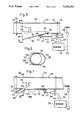
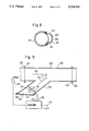
- FIG. 2A is a front view of a coarse cleaning machine incorporated into the cleaning or blow room line depicted in FIG. 1;
- FIG. 2B is a top plan view of the coarse cleaning machine of FIG. 2A;
- FIG. 3 is a schematic side view of a blender or mixing machine containing a subsequently or downstream arranged cleaning location or site and incorporated into the cleaning or blow room line depicted in FIG. 1;
- FIG. 4 is a schematic side view of a fine cleaning machine incorporated into the cleaning or blow room line depicted in FIG. 1;
- FIG. 5 is a schematic cross-sectional view of a first embodiment of a false air infeed unit or device which can be used in the cleaning or blow room line depicted in FIG. 1;
- FIG. 6 is a cross-sectional view of the false air infeed unit or device depicted in FIG. 5, taken substantially along the section line VI--VI thereof;
- FIG. 7 is a schematic cross-sectional view of a modified second embodiment or construction of false air infeed unit or device in contrast to that depicted in FIG. 5 and which can be used in the cleaning or blow room line depicted in FIG. 1;
- FIG. 7A is a schematic view of an alternative embodiment of a false air infeed unit or device simpler than that depicted in FIG. 7 and which can be used in the cleaning or blow room line depicted in FIG. 1;
- FIG. 8 is a cross-sectional view of the false air infeed unit or device depicted in FIG. 7, taken substantially along the section line VIII--VIII thereof;
- FIG. 9 is a schematic longitudinal sectional view of a modified third embodiment or construction of false air infeed unit or device which can be used in the cleaning or blow room line depicted in FIG. 1;
- FIG. 10 is a graph illustrating the relationship between the measured static pressure and the volume flow at a pressure measuring location.
- FIG. 11 schematically illustrates the pneumatic conditions prevailing between the blender and both of the fine cleaning machines of the cleaning or blow room line of FIG. 1 defining a product line.
- the cleaning or blow room line 1 depicted therein and defining a product line comprises a bale opening machine 10 which extracts fiber flocks or flock material from a row of fiber bales 12, typically cotton bales, and delivers the removed fiber flocks to a duct or conduit 14 or the like.
- the infeed or intake of the fiber flocks is accomplished by a suction ventilator or fan 16 which subsequently supplies the fiber flocks by means of a duct or duct section 18 to a coarse cleaning machine 20.
- a pressure measuring sensor or feeler 24, an adjustable or adjustable size false air opening or infeed opening 26 and a suction ventilator or fan 28 are located at a further duct or duct section 22 downstream of the coarse cleaning machine 20.
- the suction ventilator or fan 28 delivers the stream of fiber flocks into the filling or flock chutes of a multi-chute blender or mixing device 30.
- the transport or conveying air escapes as exhaust or waste air in the direction of the arrow 32.
- the blended or admixed fiber flocks are again delivered to a duct or duct section 34 which merges by means of a further adjustable false air opening 36 with two branch lines or conduits 38 and 40.
- Each such branch line 38 and 40 leads to an associated fine cleaning machine 42 and 44, respectively.
- the pressure prevailing in the duct or duct section 34 is measured by a pressure sensor or feeler 46 directly upstream of the false air opening 36.
- the air responsible for the transport of the fiber flocks emerges from both of the fine cleaning machines 42 and 44, as schematically indicated by the air flow arrows 48 and 50, respectively.
- the quantities of exhaust or waste air, indicated by the arrows 32, 48 and 50, do not merely exhaust into the atmosphere, rather are conducted by further ducts or duct sections (not shown) to a suitable filter installation where there is filtered out any possibly entrained dust, contaminants and waste.
- the finely cleaned fiber flocks are either sucked into a duct or conduit 52 or into a duct or conduit 54, and specifically, by the associated suction ventilators or fans 56 and 58.
- each duct 52 and 54 there is provided a respective pressure or pressure measuring sensor or feeler 60 and 62, respectively, and a respective false air opening or infeed opening 64 and 66.
- the stream of fiber flocks is delivered, as indicated by the arrows 68 and 70, to the carding room, typically to the feed or filling chutes of the associated cards, simply generally indicated by reference numeral 95 in FIG. 1.
- suction ventilators 16, 28, 56 and 58 there are provided additional ventilators or fans which are installed at the machines and which also participate in the transport or processing of the fiber flocks.
- the cleaning line defining the product line constitutes a rather complex assembly as concerns the pneumatic or air flow aspects. It is also here to be mentioned that the disclosure given herein is only representative of an example of a product line. In actual practice, there can be present many different cleaning or blow room lines defining product lines.
- FIGS. 2A and 2B For purposes of setting forth a more detailed explanation of the function of the coarse cleaning machine 20.
- the coarse cleaning machine 20 is constructed as a so-called mono-roll cleaner which is available from the present assignee of this application.
- the fiber flocks namely, the cotton flocks delivered by the duct or conduit 18 arrive in a direction which is essentially perpendicular to the lengthwise axis of a rotating pin roll or roller 72 in the coarse cleaning machine 20.
- the rotating pin roll 72 leads the cotton flocks over a grate or grid 74, accelerates such cotton flocks upwardly into a hood or hood member 76 and again engages such cotton flocks.
- the cotton flocks are turned or tumbled a number of times as they are upwardly propelled or accelerated into the hood 76, all sides of such cotton flocks come into contact with the grate or grid 74. These operations explain the exceedingly effective and protective cleaning function of the mono-roll coarse cleaning machine 20. Moreover, the entire cleaning procedure repeats at least three times, since there are provided three inclined sheet metal guides 80 or the like in the hood 76, which force each of the individual cotton flocks to fly in a substantially helical path about the pin roll or roller 72.
- a contaminant- and waste collecting chamber or compartment 6 is located beneath the grate or grid 74, and the possibility exists of sucking off the waste or the like which has collected in this contaminant- and waste collecting chamber or compartment 6 at regular time intervals by means of a suction line or conduit 84.
- the thus cleaned fiber flocks depart from the coarse cleaning machine 20 through the delivery or outlet stud or connection 88 after completing a number of revolutions about the pin roll 72.
- This delivery or outlet stud or connection 88 merges with the duct or conduit 22 (FIG. 1).
- the pressure or pressure measuring sensor 22 measures the pressure prevailing in the duct 22 and delivers a pressure signal which is dependent upon the volume flow through such duct 22.
- FIG. 10 depicts such dependency, and will be seen that increasing negative pressure or vacuum corresponds to an increasing volume flow . It will be appreciated that ducts or conduits of spinning mills are usually operated under vacuum conditions in order prevent the formation of fiber fly.
- the pressure sensor 24 also, however, could be arranged downstream of the false air opening or infeed opening 26, as such has been depicted in FIG. 2A by reference character 24.1. Also depicted in FIG. 2A is the possible arrangement of the pressure sensor 24 or 24.1 at the region of the infeed duct 18.
- regulator 90 such can be constituted by any suitable regulator, for example, a regulator having a PI-behavior behavior or a PID-behavior.
- the regulation operation can be also accomplished by a computer which is available any way for regulating or adjusting the entire cleaning or blow room line. Therefore, in the context of this disclosure the term "regulator” is used in its broader sense to encompass not only a regulator as such, but also a “control” and equally a computer which can achieve the stated regulation or control operations.
- FIG. 3 there is shown the manner in which the duct or conduit 22 delivers the flock stream composed of air and fiber flocks into a chamber or compartment 100 which is sub-divided into six chutes 102. These six chutes 102 are separated from one another and from an encircling chamber or compartment 104 by means of the sheet metal sieves 108 having sieve openings or holes. The fiber flocks deposit themselves within the chutes 102 and the air escapes from these chutes 102 into the chamber or compartment 104 and thereafter flows through an exhaust air stud or connection 110 to the aforementioned filter installation.
- the fiber flocks located at the lower end of each of the chutes 102 move further in the form of a layered or sandwich structure 112 upon the upper run 114 of a conveyor belt or band 116 or equivalent structure. Due to the different length movement paths of the fiber flocks there occurs a beneficial admixing and homogenization of the fiber flock blend or mixture.
- Reference numerals 122 and 124 designate evener or stripper rolls or the like.
- the filling chute 126 At the lower end of the filling chute 126 there are located two delivery or outlet rolls 128 which deliver the fiber flocks to an opening roll or roller 130 which further opens these fiber flocks and delivers them to an adjustable grate or grid 132 or the like. At this adjustable grate or grid 132 there again occurs a cleaning operation during which contaminants and fiber waste are eliminated. The fiber flock stream or flow is then sucked off through the duct or conduit section 34 by the air flow in such duct and by a false air stream entering via the false air opening or infeed opening 134, and specifically, under the suction action of blowers mounted in the feed heads of both of the fine cleaning machines 42 and 44 (see also FIG. 1).
- the pressure sensor 46 detects the pressure existing in the duct or conduit 34 and the thus measured pressure value is applied to a here not shown regulator which regulates the false air opening 36, so that due to the controlled infeed of false air the pressure value can be maintained at a reference or set value which likewise has been inputted to such regulator.
- a here not shown regulator which regulates the false air opening 36, so that due to the controlled infeed of false air the pressure value can be maintained at a reference or set value which likewise has been inputted to such regulator.
- the regulator has been conveniently omitted from the showing of FIG. 3 to simply the illustration, it will be understood the construction of such regulator can be carried out exactly as described for the regulator 90 used in conjunction with the coarse cleaning machine 20 depicted in FIGS. 2A and 2B.
- the fiber flock stream or flow is delivered to the respective cleaning machine 42 and 44 by means of the respective ducts or conduits 38 and 40, and specifically, by virtue of the suction action of a suction blower 150 located in the feed head of the corresponding fine cleaning machine 42 and 44.
- a suction blower 150 located in the feed head of the corresponding fine cleaning machine 42 and 44.
- the fiber flocks are delivered to an associated flock or filling chute 154 which approximately corresponds to the flock or filling chute 126 of the blender 30.
- the air which is transported along with the fiber flocks escapes at the lower end of the associated flock or filling chute 154 and is delivered by the exhaust air ducts or conduits 50 and 48, respectively, to the filter installation.
- the fiber flocks which have collected in the flock or filling chute 154 are again delivered to an opening roll or roller 160 due to the action of the plain or blind drums or cylinders 156 and the feed rolls 158.
- This opening roll 160 again opens the fiber flocks and delivers them over a further grate or grid 162 or the like, resulting in the separation of further contaminants and waste fibers which are then conveyed by a waste transport conduit or line 164 to a suitable collecting location.
- Reference numeral 166 represents the drive for the opening roll 160.
- the opened fiber flocks are then suctionally removed by the ducts or conduits 52 and 54, due to the suction action of the suction ventilators 56 and 58, respectively (see FIG. 1).
- the pressure in the ducts 52 and 54 is measured by the pressure or pressure measuring sensors 60 and 62, respectively, and employed for regulating the position of the associated adjustment or setting element of the false air infeed unit or devices 64 and 66, respectively.
- a regulator like the regulator 90 previously considered and defined in connection with the coarse cleaning machine 20.
- the pressure conditions can be influenced by the state of cleaning of the filter installation and the position of the grate or grid 162 and the outfeed of the waste by means of the duct or conduit 164 as well as also the leakage air flow entering at location 170.
- the magnitude of this leakage air flow is dependent, for instance, also upon the relevant production (kg/hour).
- the regulatable false air infeed units or devices 64 and 66 enable obtaining essentially constant air flow conditions at the cleaning locations.
- FIG. 11 There is schematically depicted in such FIG. 11, based upon a practical embodiment, the air flow conditions prevailing between the blender 30 and both of the fine cleaning machines 42 and 44.
- both fine cleaning machines 42 and 44 at standard temperature and standard pressure, an air throughput or throughflow of 0.4 m 3 /sec. Normally the same air flow is also provided at the outlet side of the blender 30, that is, likewise 0.4 m 3 /sec. If both of the fine cleaning machines 42 and 44 are simultaneously in operation, there then prevails a total air flow quantity of 0.8 m 3 /sec., so that the air flow quantity of 0.41 m 3 /sec. emerging from the blender 30 is insufficient.
- FIGS. 5 and 6 there is depicted therein a first exemplary embodiment of false air infeed unit or device, generally indicated in its entirety by reference character 220, the adjusting or setting element 190 of which comprises a closure element in the form of a flap or flap member 196 which is hingedly connected at by the hinge or pivot means 204 at its downstream end 192 at the wall or surface 200 of the associated duct or conduit.
- this flap 196 has an essentially U-shaped cross-section, wherein this U-shape is shown resting on its side, and wherein, both of the legs 198 of the U-shaped flap 196 sealingly slide at the curved circular-shaped surface or wall 200 of the duct 202.
- Pivoting of the flap 196 can be performed by an adjustment or positioning motor 208 or equivalent structure which contains an adjustable or displaceable threaded spindle 212 movable in the direction of the double-headed arrow 210.
- This threaded spindle 212 is articulated at its left end shown in FIG. 5, at location 214 at the flap 196, by means of a fitting or bracket 216 acting as a lever.
- the adjustment or positioning motor 208 is connected by an angle bracket 218 or equivalent connection means with the duct or conduit 202.
- This adjustment or positioning motor 208 can, for example, drivingly rotate a spherical or ball nut or nut member cooperating with the threaded spindle 212, so that this threaded spindle 212 is reciprocatingly driven for lengthwise movement in the direction of the double-headed arrow 210.
- this adjustment or positioning motor 208 is rotatably connected at its end facing away from the fitting or bracket 216 with the angle bracket 218 by means of a shaft or axle 219 arranged substantially parallel to the lengthwise axis of the hinge or pivot means 204.
- false air infeed unit or device 220 which incidentally can be employed, for instance, with the false air openings or infeed openings 26, 36, 64 and 66 previously considered, is constructed as a short duct or conduit section which can be connected by the duct flanges 222 and 224 with and between further duct flanges 226 and 228, respectively of the duct structure.
- the air or pneumatic flow is carried out in the direction of the arrow 230 shown in FIG. 5.
- angle bracket 218 can be advantageously connected at the duct flange 222 and, if desired, by means of the same threaded bolts or the like which ar used to connected the duct flange 222 with the confronting duct flange 226.
- reference character 232 signifies a regulator or computer-- hereinafter simply “regulator” as previously defined--which is connected by the lines or leads 234 and 236 with the adjustment or positioning motor 208.
- This regulator 232 receives a pressure or control signal from the pressure or pressure measuring sensor or feeler 238 which, for example, can define the previously considered pressure or pressure measuring sensors 24, 46, 60 and 62, respectively.
- the pressure sensor 238 can be disposed either downstream or upstream of its adjustment or setting element 190, here defining the flap 196, depending upon which quantity of air should be maintained constant.
- this pressure sensor 238 is integrated into the false air infeed unit or device 220, so that such false air infeed unit 220 together with the pressure sensor 238 can be installed as a unit or assembly into the duct 202.
- the regulator 232 contains a reference or set value input 233, as shown in FIG. 5.
- FIGS. 7 and 8 depict a modified construction of false air infeed unit or device 220 from that shown in FIGS. 5 and 6, wherein there have been generally used the same reference characters as employed in such FIGS. 5 and 6 to denote the same or analogous structure.
- a primary difference between both of these embodiments resides in the fact that, in the embodiment of FIGS. 7 and 8 the adjustment or setting element 194 is in the form of a slide or slide element 194a, as opposed to the flap 196 of the prior embodiment of FIGS. 5 and 6.
- the controlled or adjustable displacement of the slide 194a in the direction of the double-headed arrow 210 is accomplished by an adjustment or positioning motor 208 equipped with a displaceable threaded spindle 212 which is connected, for instance, at a hinge or other suitable connection joint 214 with an attachment or bracket 216 secured to the slide 194a.
- an element 240 for example, formed of sheet metal or plating, which forms in conjunction with, for example, a sheet metal element or part 242 an air infeed channel 244.
- This air infeed channel 244 is bounded at its upper and lower ends by plates or closures 246, in order to define the false air infeed opening 206.
- plates or closures 246, In FIG. 7 there is only visible the one lower plate or closure 246.
- These plates 246 are connected, for instance, with the element or part 240 and can slide past the side edges of the confronting element or part 242.
- the element 240 Upon actuation of the rotatable threaded spindle 212 of the adjustment or positioning motor 208 in one direction of rotation, then the element 240 assumes its extreme or terminal left-hand position in FIG. 7 where it abuts against the confronting element or part 242, and thus, obturates the false air opening or infeed opening 206.
- the false air opening 206 is here formed by a connection or stud 250 defining a branch line or conduit, the free cross-section of which is controlled by a controllable closure in the form of a so-called butterfly valve or gate 195.
- This butterfly valve 195 is fastened to a pivot shaft or axle 252 disposed substantially perpendicular to the lengthwise axis of the connection or stud 250.
- An adjustment or positioning motor 254 governs the rotational position of the butterfly valve 195. In the showing of FIG. 9, this adjustment or positioning motor 254 is shown located beneath the connection o stud 250 and is appropriately attached thereto.
- the adjustment or positioning motor 254 directly drives the pivot shaft or axle 252, and thus, selectively alters the position of the butterfly valve 195 between the extreme closed valve position shown in full lines in FIG. 9 and the broken line depicted maximum open valve position.
- reference character 256 here designates a coarse mesh filter which protects against entry of unwanted contaminants and foreign particles into the connection or stud 250 and into the duct 202. It is to be noted that a corresponding filter 256 can be used with the prior considered embodiments of FIGS. 5 to 8.
Landscapes
- Engineering & Computer Science (AREA)
- Textile Engineering (AREA)
- Preliminary Treatment Of Fibers (AREA)
Applications Claiming Priority (2)
| Application Number | Priority Date | Filing Date | Title |
|---|---|---|---|
| DE4026330 | 1990-08-20 | ||
| DE4026330A DE4026330A1 (de) | 1990-08-20 | 1990-08-20 | Putzereilinie |
Publications (1)
| Publication Number | Publication Date |
|---|---|
| US5224243A true US5224243A (en) | 1993-07-06 |
Family
ID=6412571
Family Applications (1)
| Application Number | Title | Priority Date | Filing Date |
|---|---|---|---|
| US07/745,715 Expired - Fee Related US5224243A (en) | 1990-08-20 | 1991-08-16 | Cleaning line with false air infeed valve for regulating air flow therein |
Country Status (4)
| Country | Link |
|---|---|
| US (1) | US5224243A (fr) |
| EP (1) | EP0475073B1 (fr) |
| JP (1) | JPH04245927A (fr) |
| DE (2) | DE4026330A1 (fr) |
Cited By (7)
| Publication number | Priority date | Publication date | Assignee | Title |
|---|---|---|---|---|
| US5425158A (en) * | 1990-11-13 | 1995-06-20 | Ripley; W. G. | Method for producing a bleached cotton, nonwoven web |
| US5617613A (en) * | 1990-11-13 | 1997-04-08 | Ripley; William G. | System for producing a bleached cotton, nonwoven web |
| US6421883B1 (en) | 1999-11-24 | 2002-07-23 | Maschinenfabrik Rieter Ag | Selective cleaning line |
| US20080025801A1 (en) * | 2006-07-27 | 2008-01-31 | Newbolt Richard E | Vacuum modulating air control valve apparatus |
| US20180355519A1 (en) * | 2017-06-08 | 2018-12-13 | Maschinenfabrik Rieter Ag | Production Control in a Blow Room |
| CN109423714A (zh) * | 2017-08-30 | 2019-03-05 | 里特机械公司 | 用于调节清洁器中的纤维棉束流的装置 |
| CN113718380A (zh) * | 2020-05-22 | 2021-11-30 | 里特机械公司 | 纤维制备中的垃圾运输系统 |
Families Citing this family (6)
| Publication number | Priority date | Publication date | Assignee | Title |
|---|---|---|---|---|
| CN101824674A (zh) * | 2010-05-04 | 2010-09-08 | 滁州安兴环保彩纤有限公司 | 纤维混配设备及纤维混配方法 |
| CN112840067A (zh) * | 2018-07-09 | 2021-05-25 | T·J·苏塔利亚 | 将纤维材料从多个腔室选择性地注入到单个腔室中的方法和设备 |
| WO2020012257A1 (fr) * | 2018-07-09 | 2020-01-16 | Tarang J SUTARIA | Procédé et appareil de mélange fin de matières fibreuses |
| CH715422A1 (de) * | 2018-10-02 | 2020-04-15 | Rieter Ag Maschf | Faservorbereitung mit einer Abfolge von Maschinen. |
| CH717947A1 (de) * | 2020-10-13 | 2022-04-14 | Rieter Ag Maschf | Spinnereivorbereitungsmaschine zum Mischen von Fasern. |
| CH719434A1 (de) | 2022-02-18 | 2023-08-31 | Rieter Ag Maschf | Spinnereivorbereitungsmaschine zum Mischen von Fasern. |
Citations (27)
| Publication number | Priority date | Publication date | Assignee | Title |
|---|---|---|---|---|
| US1159168A (en) * | 1915-05-20 | 1915-11-02 | Christopher C Broome | Separator for cotton-ginning mechanism. |
| US1646656A (en) * | 1927-10-25 | Cotton-gin lint fltje | ||
| US1842438A (en) * | 1930-08-23 | 1932-01-26 | Platt Brothers & Co Ltd | Automatic control of pneumatically conveyed cotton or such like |
| US2014844A (en) * | 1934-11-27 | 1935-09-17 | Seymour S Holt | Method and means for handling textile fibers |
| US2891576A (en) * | 1955-03-29 | 1959-06-23 | Barber Colman Co | Air mixing damper |
| US2986373A (en) * | 1957-01-16 | 1961-05-30 | James Gordon & Co Ltd | Butterfly valves |
| DE1152949B (de) * | 1956-10-18 | 1963-08-14 | Edmond Jeanne | Selbsttaetige Saugluftfoerderanlage fuer mit Wollschweiss behaftete Wolle |
| US3280474A (en) * | 1963-10-01 | 1966-10-25 | Lummus Cotton Gin Co | Process and apparatus for moisture conditioning seed cotton and like materials |
| US3363286A (en) * | 1965-03-29 | 1968-01-16 | Howard A Scott | Method and apparatus for controlling the moisture content of natural fibers for cleaning and ginning |
| US3408115A (en) * | 1965-04-03 | 1968-10-29 | Neu Ets | Apparatus and method for distributing textile fibers |
| US3414329A (en) * | 1966-09-29 | 1968-12-03 | Continental Moss Gordin Inc | Pneumatic cotton feeder with bypass |
| US3435484A (en) * | 1966-01-18 | 1969-04-01 | Curlator Corp | Fiber distributing system |
| US3567288A (en) * | 1969-02-03 | 1971-03-02 | Curlator Corp | Pneumatic fiber conveying system |
| US3930285A (en) * | 1973-10-24 | 1976-01-06 | Alfred Proctor Aldrich, Jr. | Apparatus and method for forming staple fibers and feeding the same to a picker |
| US4085977A (en) * | 1970-02-12 | 1978-04-25 | Carding Specialists Co. Limited | Feeding of fibrous material to carding machines |
| GB2010936A (en) * | 1977-12-24 | 1979-07-04 | Platt Saco Lowell Ltd | Apparatus for opening cleaning and carding fibres |
| US4301573A (en) * | 1979-06-18 | 1981-11-24 | Gunter & Cooke, Inc. | Fiber processing apparatus and method |
| DE3127544A1 (de) * | 1981-07-11 | 1983-01-20 | Trützschler GmbH & Co KG, 4050 Mönchengladbach | Vorrichtung zum oeffnen und reinigen von faserflocken |
| GB2127446A (en) * | 1982-07-31 | 1984-04-11 | Truetzschler & Co | Method and apparatus for air-conditioning a spinning preparation installation |
| US4541611A (en) * | 1982-11-15 | 1985-09-17 | Ford Motor Company | Arrangement for controlling an air duct |
| EP0181452A1 (fr) * | 1984-10-30 | 1986-05-21 | Maschinenfabrik Rieter Ag | Conduit de transport pour flocons de fibre |
| FR2573780A1 (fr) * | 1984-11-24 | 1986-05-30 | Truetzschler & Co | Installation pour l'alimentation pneumatique en fibre d'un nombre variable de cadres |
| US4723344A (en) * | 1985-04-13 | 1988-02-09 | Trutzschler Gmbh & Co. Kg | Method and apparatus for opening fiber bales |
| US4783048A (en) * | 1987-12-17 | 1988-11-08 | St Clair Thomas W | Slide gate damper system |
| SU1601221A1 (ru) * | 1988-06-20 | 1990-10-23 | Фрунзенский политехнический институт | Устройство дл пневмотранспорта отходов текстильного производства |
| JPH02263327A (ja) * | 1989-03-31 | 1990-10-26 | Toshiba Corp | 光記録媒体の記録再生装置 |
| US5021149A (en) * | 1988-07-01 | 1991-06-04 | Aspa Zurich AG | Process and device for processing granulated materials |
Family Cites Families (5)
| Publication number | Priority date | Publication date | Assignee | Title |
|---|---|---|---|---|
| GB1075144A (en) * | 1963-08-07 | 1967-07-12 | G Radaelli S P A Ing | Pneumatic system for automatically supplying textile machines preparatory to spinning |
| DE1971420U (de) * | 1966-09-03 | 1967-10-26 | Truetzschler & Co | Vorrichtung zum foerdern von fasern od. dgl. mittels luftdruck. |
| CH516660A (de) * | 1968-11-20 | 1971-12-15 | Rieter Ag Maschf | Verfahren zum Speisen von Karden mit einem pneumatischen Flockenfördersystem und Vorrichtung zur Durchführung des Verfahrens |
| DE3237864C2 (de) * | 1982-10-13 | 1996-05-23 | Truetzschler Gmbh & Co Kg | Verfahren und Vorrichtung zum Steuern und Regeln einer Spinnereivorbereitungsanlage |
| US4864693A (en) * | 1988-09-30 | 1989-09-12 | Hergeth Hollingsworth Gmbh | Flow-through fiber preparation feed system and method |
-
1990
- 1990-08-20 DE DE4026330A patent/DE4026330A1/de not_active Withdrawn
-
1991
- 1991-08-06 EP EP91113208A patent/EP0475073B1/fr not_active Revoked
- 1991-08-06 JP JP3196692A patent/JPH04245927A/ja active Pending
- 1991-08-06 DE DE59107806T patent/DE59107806D1/de not_active Expired - Lifetime
- 1991-08-16 US US07/745,715 patent/US5224243A/en not_active Expired - Fee Related
Patent Citations (27)
| Publication number | Priority date | Publication date | Assignee | Title |
|---|---|---|---|---|
| US1646656A (en) * | 1927-10-25 | Cotton-gin lint fltje | ||
| US1159168A (en) * | 1915-05-20 | 1915-11-02 | Christopher C Broome | Separator for cotton-ginning mechanism. |
| US1842438A (en) * | 1930-08-23 | 1932-01-26 | Platt Brothers & Co Ltd | Automatic control of pneumatically conveyed cotton or such like |
| US2014844A (en) * | 1934-11-27 | 1935-09-17 | Seymour S Holt | Method and means for handling textile fibers |
| US2891576A (en) * | 1955-03-29 | 1959-06-23 | Barber Colman Co | Air mixing damper |
| DE1152949B (de) * | 1956-10-18 | 1963-08-14 | Edmond Jeanne | Selbsttaetige Saugluftfoerderanlage fuer mit Wollschweiss behaftete Wolle |
| US2986373A (en) * | 1957-01-16 | 1961-05-30 | James Gordon & Co Ltd | Butterfly valves |
| US3280474A (en) * | 1963-10-01 | 1966-10-25 | Lummus Cotton Gin Co | Process and apparatus for moisture conditioning seed cotton and like materials |
| US3363286A (en) * | 1965-03-29 | 1968-01-16 | Howard A Scott | Method and apparatus for controlling the moisture content of natural fibers for cleaning and ginning |
| US3408115A (en) * | 1965-04-03 | 1968-10-29 | Neu Ets | Apparatus and method for distributing textile fibers |
| US3435484A (en) * | 1966-01-18 | 1969-04-01 | Curlator Corp | Fiber distributing system |
| US3414329A (en) * | 1966-09-29 | 1968-12-03 | Continental Moss Gordin Inc | Pneumatic cotton feeder with bypass |
| US3567288A (en) * | 1969-02-03 | 1971-03-02 | Curlator Corp | Pneumatic fiber conveying system |
| US4085977A (en) * | 1970-02-12 | 1978-04-25 | Carding Specialists Co. Limited | Feeding of fibrous material to carding machines |
| US3930285A (en) * | 1973-10-24 | 1976-01-06 | Alfred Proctor Aldrich, Jr. | Apparatus and method for forming staple fibers and feeding the same to a picker |
| GB2010936A (en) * | 1977-12-24 | 1979-07-04 | Platt Saco Lowell Ltd | Apparatus for opening cleaning and carding fibres |
| US4301573A (en) * | 1979-06-18 | 1981-11-24 | Gunter & Cooke, Inc. | Fiber processing apparatus and method |
| DE3127544A1 (de) * | 1981-07-11 | 1983-01-20 | Trützschler GmbH & Co KG, 4050 Mönchengladbach | Vorrichtung zum oeffnen und reinigen von faserflocken |
| GB2127446A (en) * | 1982-07-31 | 1984-04-11 | Truetzschler & Co | Method and apparatus for air-conditioning a spinning preparation installation |
| US4541611A (en) * | 1982-11-15 | 1985-09-17 | Ford Motor Company | Arrangement for controlling an air duct |
| EP0181452A1 (fr) * | 1984-10-30 | 1986-05-21 | Maschinenfabrik Rieter Ag | Conduit de transport pour flocons de fibre |
| FR2573780A1 (fr) * | 1984-11-24 | 1986-05-30 | Truetzschler & Co | Installation pour l'alimentation pneumatique en fibre d'un nombre variable de cadres |
| US4723344A (en) * | 1985-04-13 | 1988-02-09 | Trutzschler Gmbh & Co. Kg | Method and apparatus for opening fiber bales |
| US4783048A (en) * | 1987-12-17 | 1988-11-08 | St Clair Thomas W | Slide gate damper system |
| SU1601221A1 (ru) * | 1988-06-20 | 1990-10-23 | Фрунзенский политехнический институт | Устройство дл пневмотранспорта отходов текстильного производства |
| US5021149A (en) * | 1988-07-01 | 1991-06-04 | Aspa Zurich AG | Process and device for processing granulated materials |
| JPH02263327A (ja) * | 1989-03-31 | 1990-10-26 | Toshiba Corp | 光記録媒体の記録再生装置 |
Cited By (12)
| Publication number | Priority date | Publication date | Assignee | Title |
|---|---|---|---|---|
| US5425158A (en) * | 1990-11-13 | 1995-06-20 | Ripley; W. G. | Method for producing a bleached cotton, nonwoven web |
| US5617613A (en) * | 1990-11-13 | 1997-04-08 | Ripley; William G. | System for producing a bleached cotton, nonwoven web |
| US5634243A (en) * | 1990-11-13 | 1997-06-03 | Ripley; W. G. | System and method for producing a bleached cotton, nonwoven web |
| US6421883B1 (en) | 1999-11-24 | 2002-07-23 | Maschinenfabrik Rieter Ag | Selective cleaning line |
| US20080025801A1 (en) * | 2006-07-27 | 2008-01-31 | Newbolt Richard E | Vacuum modulating air control valve apparatus |
| US7740423B2 (en) * | 2006-07-27 | 2010-06-22 | Mac Equipment, Inc. | Vacuum modulating air control valve apparatus |
| US20180355519A1 (en) * | 2017-06-08 | 2018-12-13 | Maschinenfabrik Rieter Ag | Production Control in a Blow Room |
| US10619270B2 (en) * | 2017-06-08 | 2020-04-14 | Maschinenfabrik Rieter Ag | Production control in a blow room |
| CN109423714A (zh) * | 2017-08-30 | 2019-03-05 | 里特机械公司 | 用于调节清洁器中的纤维棉束流的装置 |
| EP3450597A1 (fr) * | 2017-08-30 | 2019-03-06 | Maschinenfabrik Rieter AG | Dispositif de réglage d'un flux de flocons de fibres dans une machine de nettoyage |
| CN109423714B (zh) * | 2017-08-30 | 2022-06-24 | 里特机械公司 | 用于调节清洁器中的纤维棉束流的装置 |
| CN113718380A (zh) * | 2020-05-22 | 2021-11-30 | 里特机械公司 | 纤维制备中的垃圾运输系统 |
Also Published As
| Publication number | Publication date |
|---|---|
| EP0475073A1 (fr) | 1992-03-18 |
| EP0475073B1 (fr) | 1996-05-15 |
| DE59107806D1 (de) | 1996-06-20 |
| JPH04245927A (ja) | 1992-09-02 |
| DE4026330A1 (de) | 1992-02-27 |
Similar Documents
| Publication | Publication Date | Title |
|---|---|---|
| US5224243A (en) | Cleaning line with false air infeed valve for regulating air flow therein | |
| JP3242959B2 (ja) | 化学繊維、木綿、スフなどから繊維フリースを形成する装置 | |
| CN101903264A (zh) | 用于气动的物料输送系统的方法和气动的物料输送系统 | |
| GB2338965A (en) | Arrangement for guiding textile fibre flocks | |
| EP2867392A1 (fr) | Procédé et dispositif pour réguler l'alimentation en fibres d'une cardeuse | |
| GB2104560A (en) | Device and method for delivering fibre flocks | |
| US3435484A (en) | Fiber distributing system | |
| US5143485A (en) | Transport air control | |
| GB2169322A (en) | Device and method for the pneumatic feeding of fibres | |
| US6905528B2 (en) | Conveying air filtration system | |
| US5226213A (en) | Rake valve for air-fiber streams | |
| CH695829A5 (de) | Vorrichtung zum Ausscheiden von Fremdkörpern aus Fasermaterial. | |
| US5197162A (en) | Apparatus having partial exhaust conduit fiber compacting air flow | |
| RU1834925C (ru) | Способ обработки хлопка, загр зненного широй и устройство дл его осуществлени | |
| DE19806891A1 (de) | Vorrichtung in der Spinnereivorbereitung zum Abscheiden und Beschicken von Fasermaterial, z. B. Baumwolle und dgl. zu einer Verarbeitungsmaschine | |
| US4085977A (en) | Feeding of fibrous material to carding machines | |
| GB2334532A (en) | Preparing fibres for spinning : separating foreign matter | |
| DE3916986A1 (de) | Verteiler zur speisung einer mehrzahl von schaechten | |
| GB2294702A (en) | Fibre feed: seperating fibre flocks from air current | |
| US3112139A (en) | Automatic carding plant | |
| GB2346623A (en) | Arrangement for filling a fibre flock store | |
| CH696301A5 (de) | Vorrichtung an einer Reinigungsvorrichtung, z. B. an einer Reinigungsmaschine, einer Öffnungsmaschine oder einer Karde, für Fasermaterial, z. B. Baumwolle oder Chemiefasern. | |
| CZ308782B6 (cs) | Způsob regulace průtoku nebo tlaku v zařízení na dopravu odpadu v přípravě vlákna a zařízení | |
| GB1564827A (en) | Suction apparatus for textile machines | |
| AU700927B3 (en) | Adjustable guide vanes |
Legal Events
| Date | Code | Title | Description |
|---|---|---|---|
| AS | Assignment |
Owner name: MASCHINENFABRIK RIETER AG Free format text: ASSIGNMENT OF ASSIGNORS INTEREST.;ASSIGNORS:SCHLEPFER, WALTER;HAUSCHILD, WERNER;FAAS, JURG;AND OTHERS;REEL/FRAME:005827/0965;SIGNING DATES FROM 19910812 TO 19910813 |
|
| FEPP | Fee payment procedure |
Free format text: PAYOR NUMBER ASSIGNED (ORIGINAL EVENT CODE: ASPN); ENTITY STATUS OF PATENT OWNER: LARGE ENTITY |
|
| REMI | Maintenance fee reminder mailed | ||
| LAPS | Lapse for failure to pay maintenance fees | ||
| FP | Lapsed due to failure to pay maintenance fee |
Effective date: 19970709 |
|
| STCH | Information on status: patent discontinuation |
Free format text: PATENT EXPIRED DUE TO NONPAYMENT OF MAINTENANCE FEES UNDER 37 CFR 1.362 |