EP0475073A1 - Ligne de nettoyage - Google Patents
Ligne de nettoyage Download PDFInfo
- Publication number
- EP0475073A1 EP0475073A1 EP91113208A EP91113208A EP0475073A1 EP 0475073 A1 EP0475073 A1 EP 0475073A1 EP 91113208 A EP91113208 A EP 91113208A EP 91113208 A EP91113208 A EP 91113208A EP 0475073 A1 EP0475073 A1 EP 0475073A1
- Authority
- EP
- European Patent Office
- Prior art keywords
- pipeline
- cleaning
- blowroom
- cleaning machine
- opening
- Prior art date
- Legal status (The legal status is an assumption and is not a legal conclusion. Google has not performed a legal analysis and makes no representation as to the accuracy of the status listed.)
- Granted
Links
Images


Classifications
-
- D—TEXTILES; PAPER
- D01—NATURAL OR MAN-MADE THREADS OR FIBRES; SPINNING
- D01G—PRELIMINARY TREATMENT OF FIBRES, e.g. FOR SPINNING
- D01G23/00—Feeding fibres to machines; Conveying fibres between machines
- D01G23/08—Air draught or like pneumatic arrangements
-
- D—TEXTILES; PAPER
- D01—NATURAL OR MAN-MADE THREADS OR FIBRES; SPINNING
- D01G—PRELIMINARY TREATMENT OF FIBRES, e.g. FOR SPINNING
- D01G13/00—Mixing, e.g. blending, fibres; Mixing non-fibrous materials with fibres
Definitions
- the present invention relates to a blowroom line consisting of at least one bale removal machine, which is connected via pipes and at least one cleaning machine and a mixer with a plurality of cards, the transport of the flakes removed from the bale removal machine through the blowroom line being able to be carried out by means of suction fans present therein, and one Process for controlling a cleaning line of this type.
- blowroom lines are well known in spinning technology, so that a precise explanation of the meaning and purpose of such a blowroom line is unnecessary.
- Blowroom machines are usually equipped with cleaning points, whereby the cleaning effect of these machines is partly dependent on the material extraction, i.e. the cleaning effect of these machines is partly influenced by the material suction.
- the air conditions in the material extraction are not always constant, but are changed unintentionally by various external influences, for example depending on whether the assigned filter system is currently being cleaned or is due for the next cleaning.
- the invention provides that, after at least one cleaning machine or cleaning point, a pressure sensor is provided in the pipeline, the signal of which can be applied to a control unit which controls or regulates the size of a false air opening which also determines the air flow through the pipeline.
- this setpoint can be selected according to the respective production (kg / hour) and by regulating the size of an opening determining the size of the airflow, the actual values can be achieved with simple means.
- Set the pressure value in the area of the sensor so that it largely corresponds to the setpoint. Since the adjustable false air opening is preferably arranged immediately upstream or downstream of the pressure sensor, it is still possible to set the desired constant air conditions at this point without pronounced changes occurring at other points on the blowroom line. At least one can express that once the system has been set up correctly, the control effect via the controllable false air openings only largely leads to local changes in the air conditions, but not to fundamental changes in the air conditions through the entire cleaning line.
- the control is thus used to keep the pressure or the volume flow in the pipeline constant, i.e. designed in the area of the sensor.
- the cleaning machine can, for example, be a fine cleaning machine, the false air opening being arranged in the pipeline downstream of the cleaning machine and preferably also downstream of the pressure sensor assigned to it.
- the same also applies to a cleaning machine in the form of a coarse cleaning machine, and in a corresponding manner even if it is only a cleaning point which is provided at the end of a mixer.
- the compressed air sensor can be arranged upstream or downstream of the false air supply opening, depending on the amount of air that has to be kept constant.
- the false air opening can be determined, for example, by a flap which can be pivoted by means of a motor, which flap can preferably be pivoted outward from a closed position flush with the wall of the pipeline about a joint provided at its downstream end.
- the false air opening can, however, also be formed by a motor-displaceable slide or by a pivoting butterfly valve, in which case the butterfly valve which is pivoted by motor is preferably formed in a branch line opening into the pipeline.
- the function of the controller can be formed by a computer that controls or regulates the blowroom unit and / or the cleaning machine in question.
- the invention therefore presents itself as a combination of a false air supply unit which has a motor-adjustable opening and can be installed in a pipeline a pressure sensor which can also be installed in the pipeline and which controls or regulates the size of the adjustable opening via a control or regulating unit in order to maintain a specifiable pressure or volume flow.
- the present invention also includes, as explained at the outset, a method for controlling a cleaning line of the type mentioned at the outset, the method being characterized in that the size of at least one in order to maintain constant or predeterminable pressure or volume flow ratios in the pipelines In the pipeline provided false air opening is controlled by means of a pressure signal picked up by a pressure sensor by comparison with a predetermined target value.
- the product line of FIG. 1 consists of a bale removal machine 10, which removes flake material from a bale stick 12 and feeds it into a pipeline 14 in flake form. This feed takes place by means of a suction fan 16, which then delivers the flakes to a coarse cleaning machine 20 via the pipe section 18.
- a pressure measurement sensor 24 In the pipeline section 22 after the coarse cleaning machine 20 there is a pressure measurement sensor 24, an adjustable false air opening 26 and a suction fan 28 which delivers the flock flow in the shafts of a multi-shaft mixer 30.
- the transport air escapes as exhaust air in the direction of arrow 32.
- the mixed flakes are fed back into a pipeline section 34, which merges into two branch lines 38 and 40 via a further adjustable false air supply opening 36, which each lead to a fine cleaning machine 42 or 44.
- the pressure prevailing in the line section 34 is measured by means of a pressure sensor 46 directly upstream of the false air supply opening 36.
- the air for the flock transport escapes from the two fine cleaning machines 42 and 44 as shown by the arrows 48 and 50.
- These exhaust air quantities 32, 48 and 50 not only flow into the ambient air, but also lead via further lines (not shown) to a filter system, where any dust, dirt and waste which is also transported is filtered out.
- the finely cleaned flakes are sucked either into the pipeline 52 or into the pipeline 54 by means of the respective suction fans 56 and 58, with a respective pressure measurement sensor 60 and 62 and a respective false air opening 64 in each pipeline 52 and 54 , 66 is provided.
- the suction fans 56, 58 the flake flow is led to the carding machine in accordance with the arrows 68, 70, usually to the feed chutes of the respective carding machine.
- the product line represents a complex structure from the ventilation point of view. It should also be emphasized here that this is only an example of a product line. In practice, many different blowroom lines can occur.
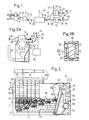
- FIGS. 2A and 2B In order to explain the effect of the coarse cleaning machine in more detail, reference is first made to FIGS. 2A and 2B.
- the coarse cleaning machine has the form of a so-called mono-roller cleaner of the present applicant, the cotton flakes supplied by the pipeline 18 being perpendicular to the axis se a rotating pin roller 72 enter the machine.
- the pin roller guides the flakes over a grate 74, hurls them up into a hood 76 and grips them again. Since the flakes are flipped over several times in the hood, they come into contact with the grate 74 on all sides.
- baffles 80 are provided in the hood, which force each individual flake to fly in a helical path around the pin roller.
- a dirt and outlet collecting space 6 is located below the grate, and there is the possibility of sucking the dirt accumulated here out of the outlet space at regular time intervals by means of a suction line 84.
- the pressure sensor could also be arranged upstream of the false air supply, as shown in FIG. 2A at 24.1.
- Any conventional controller for example a controller with PI or PID behavior, can be used for the controller.
- the control function can also be carried out by a computer, for example by a computer which is in any case responsible for regulating or setting the entire cleaning line.
- FIG. 3 shows how the pipeline 22 delivers the flake stream consisting of air and flakes into a chamber 100 which is divided into six shafts 102. These six shafts are separated from one another and from a space 104 surrounding them by means of perforated plates with holes 108, the flakes being deposited in the shafts and the air passing from the shafts into the space 104 and then being passed on to the filter system via an exhaust port 110. The flakes located at the lower end of the shafts continue to move into a layered structure 112 on the upper run 114 of a conveyor belt 116, with mixing and homogenization of the mixture occurring due to the different lengths of the flake paths.
- the layered structure 112 the movement of which is supported by a transport roller 118, is opened at the right end of the conveyor belt by a needle lattice cloth 120, which is also designed as a conveyor belt, and is dissolved in a stream of flakes carried by it, which is filled into a filling shaft 126.
- the reference numerals 122 and 124 relate to rear strip rollers.
- This grate 132 in turn has a cleaning effect in which dirt and fiber loss are eliminated.
- the floc stream is then sucked off, plus a proportion of false air entering through the opening 134, above the pipeline section 34, specifically under the suction effect of the fans which are installed in the feed heads of the two fine cleaning machines 44 and 42.
- the pressure sensor 46 determines the pressure value in the pipeline 34 and the pressure value measured in this way is applied to a regulator, not shown here, which regulates the false air opening 36 in order to keep the pressure value at a setpoint value likewise entered into the regulator by controlled introduction of false air.
- the controller can be designed here in exactly the same way as it is in connection with the coarse cleaning machine according to FIGS. 2A and 2B.
- this pressure value is automatically regulated to the desired value via the assigned controller and the false air supply unit 36.
- the flock flow is delivered to the respective cleaning machine 42, 44 via the respective pipeline 38 or 40, specifically because of the suction effect of a suction fan 150 in the feed head of the fine cleaning machine.
- the flakes are delivered after the blower 150 into a flake shaft 154, which corresponds approximately to the flake shaft 126 of the mixer 30.
- the air transported with the flakes escapes at the lower end of the flake shaft and is led to the filter system via the exhaust air pipe 50 or 48.
- the flakes accumulating in the shaft 154 are in turn fed through the action of the blind drums 156 and the feed rollers 158 to an opening roller 160, which opens the flakes again and passes them through a further grate 162, as a result of which further dirt and waste fibers are excreted and via a waste transport line 164 to one Collection point to be transported.
- the drive for the rotatable opening roller 160 is identified by the reference number 166.
- the dissolved flakes are then sucked off via the pipeline 52 or 50 due to the suction effect of the fans 56 or 58 (FIG. 1).
- the pressure in the pipeline 52 or 54 is measured by means of the pressure sensor 60 or 62 and used to regulate the position of the actuator of the false air supply unit 64 or 66. This regulation in turn takes place via a controller, as described in connection with the coarse cleaning machine.
- This example also shows that the cleaning condition of the filter system and the position of the grate 162 and the removal of the outlet via line 164, as well as the leakage air flow entering at 170, can influence the pressure conditions.
- the size of this leakage air flow also depends, for example, on the respective production (kg / hour). With the controllable false air supply unit 64 or 66, constant air flow conditions can be ensured at the cleaning points.
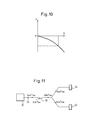
- FIG. 11 schematically shows the air flow conditions between the mixer 30 and the two fine cleaning machines 42 and 44 using a practical example.
- an air flow of 0.4 M 3 / sec is for the two fine cleaning machines. provided at normal temperature and pressure.
- the same air flow is normally also provided at the outlet of the mixer 30, ie also 0.4 M 3 / sec. If both fine cleaners 42, 44 are in operation at the same time, however, this results in a total air flow rate of 0.8 m 3 / sec., So that the air flow rate emerging from the mixer is 0.4 M 3 / sec. not enough.
- This can be compensated for by controlling the false air opening 36 in such a way that an additional air flow rate of 0.4 M 3 / sec. flows in here and thus together with the 0.4 M 3 / sec. from mixer 30 the required 0.8 M 3 / sec. forms.
- the 0.4 M 3 / sec are sufficient. from the mixer 30 completely to feed the one cleaning machine so that the false air supply unit 36 can be closed.
- the closing and opening of the false air supply unit 36 therefore takes place on the basis of the pressure measurement at the sensor 24.
- both the mixer 30 and the two fine cleaning machines 42, 44 operate with the desired flow, so that the cleaning effect remains constant. If the false air supply unit 36 were not available or if it could not be adjusted, when the second fine cleaning machine is started up, an increased air flow through the mixer would take place in addition to the first fine cleaning machine, which would change the cleaning effect of the mixer 30. It would also be expected that the air flows to the two fine cleaning machines would then not achieve the desired value of 0.4 M 3 / sec. achieved so that these machines can no longer maintain the desired constant efficiency.
- FIG. 5 shows a first example of a false air supply unit, the actuator 190 of which has the shape of a flap 196 which is articulated at its downstream end 192 and on the tube wall and which, as can be seen from FIG. 6, is approximately U-shaped in cross section (U on the side), the two side legs 198 of the U sealingly sliding on the curved circular surface 200 of the pipeline 202.
- the size of the false air supply opening 206 is adjusted by adjusting the pivoting angle of the flap 196 around the joint 204.
- This pivoting of the flap 196 can be brought about by a servomotor 208 which has a spindle 212 which is adjustable in the direction of the double arrow 210 and which at its left end at 214 on the Flap 196 is articulated via a fitting 216 serving as a lever.
- the servomotor 208 which, for example, can drive a ball nut cooperating with the spindle 212 to rotate, so that the spindle 212 is driven in a longitudinal movement in the direction of the double arrow 210, is fastened to the pipeline via an angle fitting 218.
- the servomotor is rotatably attached to the angular fitting 218 via an axis 219 arranged parallel to the axis of the joint 204.
- the false air supply unit which is identified overall by the reference number 220 and can be used, for example, for the false air supply units 26, 36, 64 or 66, is designed in the form of a short pipe section which is connected to further flanges 226 and 228 by means of flanges 222 and 224 the pipe between these other flanges can be attached.
- the flow through the pipeline takes place in the direction of arrow 230 and the angular fitting 218 can expediently be fastened to the flange 222, possibly using the screws which are used to fasten the flange 222 to the flange 226.
- the reference numeral 232 indicates a regulator or computer which is connected to the motor 208 via the lines 234 and 236, the regulator or computer 232 receiving a pressure signal from a pressure measuring sensor 238 which, for example, the pressure measuring sensor 24 or 46 or 60 or 62 can form.
- the pressure measurement sensor 238, regardless of the design of the false air supply unit, can be arranged either downstream or upstream of its actuator, depending on the amount of air that must be kept constant, and it is particularly advantageous if this pressure measurement sensor is integrated in the false air supply unit itself so that the Unit can be used as a whole in the pipeline.
- the controller 232 also has a setpoint input 233.
- FIGS. 7 and 8 show a modified version of the false air supply unit, but the same reference numerals are used to identify parts which have the same design or function as in the embodiment of FIGS. 5 and 6.
- the main difference between these two embodiments is in that the actuator 194 here has the shape of a slide instead of that of a flap.
- the adjustment of the slide in the direction of the double arrow 210 also takes place here via a servomotor 208 with a spindle 212, which (via a joint 214) engages a fitting 216 which is fastened to the slide.
- the slide has an element 240 made of sheet metal, which together with a sheet metal part 242 forms an air supply channel 244, which is delimited at the top and bottom by plates 246 (only the lower plate can be seen in FIG. 7) to define the air supply opening 206.
- plates 246 are attached to member 240 and slide over the side edges of member 242.
- the air stream 248 entering through the false air supply opening will form a sharp angle a with the air stream 230, as a result of which turbulence with the pressure losses and efficiency losses associated therewith can be largely avoided. 5 and 6, the angle ⁇ between the air 248 flowing in through the false air opening 206 and the air 230 flowing in the pipeline is kept small, for the same reason.
- the false air opening is formed by a connector 250, the free flow cross section of which is determined by a so-called butterfly valve 195, the butterfly valve 195 being fastened to a pivot axis 252 arranged perpendicular to the longitudinal axis of the connector 250, the rotational position of which is by a motor 254 is determined.
- the motor 254 is arranged below the connection piece 250 in FIG. 9 and is fastened to the latter.
- the motor drives the axis 252 directly and thus changes the position of the butterfly valve 195 between the closed position shown in FIG. 9 (solid lines) and the maximum open position (dashed lines).
- the reference numeral 256 here indicates a coarse-mesh filter 256, which prevents undesired contaminants and foreign bodies from entering the pipeline or the nozzle 250.
- a corresponding filter can also be provided in the further performances according to FIGS. 5 to 8.
- the pressure sensor 238 and possibly also the controller 232 can be integrated with the false air supply unit, so that only one structural unit results that is easy to handle and is also suitable for retrofitting.
- FIG. 7A a simpler embodiment according to FIG. 7A can also be provided.
- a circular slide 290 which is curved in accordance with the tube wall is provided and is guided on the outside of the tube wall in guides 291 and 292.
- the size of the air supply opening 206 is determined by moving the circular slide 290 in the direction of the double arrow 210.
- the circular slide 290 is actuated and controlled analogously to the exemplary embodiment in FIG. 7.
- the air 230 flowing in the pipeline is identified by a corresponding arrow.
Landscapes
- Engineering & Computer Science (AREA)
- Textile Engineering (AREA)
- Preliminary Treatment Of Fibers (AREA)
Applications Claiming Priority (2)
| Application Number | Priority Date | Filing Date | Title |
|---|---|---|---|
| DE4026330 | 1990-08-20 | ||
| DE4026330A DE4026330A1 (de) | 1990-08-20 | 1990-08-20 | Putzereilinie |
Publications (2)
| Publication Number | Publication Date |
|---|---|
| EP0475073A1 true EP0475073A1 (fr) | 1992-03-18 |
| EP0475073B1 EP0475073B1 (fr) | 1996-05-15 |
Family
ID=6412571
Family Applications (1)
| Application Number | Title | Priority Date | Filing Date |
|---|---|---|---|
| EP91113208A Revoked EP0475073B1 (fr) | 1990-08-20 | 1991-08-06 | Ligne de nettoyage |
Country Status (4)
| Country | Link |
|---|---|
| US (1) | US5224243A (fr) |
| EP (1) | EP0475073B1 (fr) |
| JP (1) | JPH04245927A (fr) |
| DE (2) | DE4026330A1 (fr) |
Cited By (4)
| Publication number | Priority date | Publication date | Assignee | Title |
|---|---|---|---|---|
| EP1103640A1 (fr) * | 1999-11-24 | 2001-05-30 | Maschinenfabrik Rieter Ag | Ligne de nettoyage sélective |
| CN101824674A (zh) * | 2010-05-04 | 2010-09-08 | 滁州安兴环保彩纤有限公司 | 纤维混配设备及纤维混配方法 |
| EP3913119A1 (fr) * | 2020-05-22 | 2021-11-24 | Maschinenfabrik Rieter AG | Système de transport de sortie dans une préparation des fibres |
| CH717947A1 (de) * | 2020-10-13 | 2022-04-14 | Rieter Ag Maschf | Spinnereivorbereitungsmaschine zum Mischen von Fasern. |
Families Citing this family (9)
| Publication number | Priority date | Publication date | Assignee | Title |
|---|---|---|---|---|
| US5425158A (en) * | 1990-11-13 | 1995-06-20 | Ripley; W. G. | Method for producing a bleached cotton, nonwoven web |
| US5617613A (en) * | 1990-11-13 | 1997-04-08 | Ripley; William G. | System for producing a bleached cotton, nonwoven web |
| WO2008013951A2 (fr) * | 2006-07-27 | 2008-01-31 | Mac Equipment, Inc. | Appareil à soupape de commande d'air de modulation sous vide |
| CH713861A1 (de) * | 2017-06-08 | 2018-12-14 | Rieter Ag Maschf | Produktionssteuerung in einer Putzerei. |
| CH714101A1 (de) * | 2017-08-30 | 2019-03-15 | Rieter Ag Maschf | Vorrichtung zur Regelung eines Faserflockenstromes in einem Reiniger. |
| CN112840067A (zh) * | 2018-07-09 | 2021-05-25 | T·J·苏塔利亚 | 将纤维材料从多个腔室选择性地注入到单个腔室中的方法和设备 |
| WO2020012257A1 (fr) * | 2018-07-09 | 2020-01-16 | Tarang J SUTARIA | Procédé et appareil de mélange fin de matières fibreuses |
| CH715422A1 (de) * | 2018-10-02 | 2020-04-15 | Rieter Ag Maschf | Faservorbereitung mit einer Abfolge von Maschinen. |
| CH719434A1 (de) | 2022-02-18 | 2023-08-31 | Rieter Ag Maschf | Spinnereivorbereitungsmaschine zum Mischen von Fasern. |
Citations (3)
| Publication number | Priority date | Publication date | Assignee | Title |
|---|---|---|---|---|
| DE3127544A1 (de) * | 1981-07-11 | 1983-01-20 | Trützschler GmbH & Co KG, 4050 Mönchengladbach | Vorrichtung zum oeffnen und reinigen von faserflocken |
| EP0181452A1 (fr) * | 1984-10-30 | 1986-05-21 | Maschinenfabrik Rieter Ag | Conduit de transport pour flocons de fibre |
| FR2573780A1 (fr) * | 1984-11-24 | 1986-05-30 | Truetzschler & Co | Installation pour l'alimentation pneumatique en fibre d'un nombre variable de cadres |
Family Cites Families (29)
| Publication number | Priority date | Publication date | Assignee | Title |
|---|---|---|---|---|
| US1646656A (en) * | 1927-10-25 | Cotton-gin lint fltje | ||
| US1159168A (en) * | 1915-05-20 | 1915-11-02 | Christopher C Broome | Separator for cotton-ginning mechanism. |
| US1842438A (en) * | 1930-08-23 | 1932-01-26 | Platt Brothers & Co Ltd | Automatic control of pneumatically conveyed cotton or such like |
| US2014844A (en) * | 1934-11-27 | 1935-09-17 | Seymour S Holt | Method and means for handling textile fibers |
| US2891576A (en) * | 1955-03-29 | 1959-06-23 | Barber Colman Co | Air mixing damper |
| DE1152949B (de) * | 1956-10-18 | 1963-08-14 | Edmond Jeanne | Selbsttaetige Saugluftfoerderanlage fuer mit Wollschweiss behaftete Wolle |
| US2986373A (en) * | 1957-01-16 | 1961-05-30 | James Gordon & Co Ltd | Butterfly valves |
| GB1075144A (en) * | 1963-08-07 | 1967-07-12 | G Radaelli S P A Ing | Pneumatic system for automatically supplying textile machines preparatory to spinning |
| US3280474A (en) * | 1963-10-01 | 1966-10-25 | Lummus Cotton Gin Co | Process and apparatus for moisture conditioning seed cotton and like materials |
| US3363286A (en) * | 1965-03-29 | 1968-01-16 | Howard A Scott | Method and apparatus for controlling the moisture content of natural fibers for cleaning and ginning |
| FR1439131A (fr) * | 1965-04-03 | 1966-05-20 | Installation pour l'alimentation en fibres d'un ensemble de machines textiles connectées en série le long d'une canalisation | |
| US3435484A (en) * | 1966-01-18 | 1969-04-01 | Curlator Corp | Fiber distributing system |
| DE1971420U (de) * | 1966-09-03 | 1967-10-26 | Truetzschler & Co | Vorrichtung zum foerdern von fasern od. dgl. mittels luftdruck. |
| US3414329A (en) * | 1966-09-29 | 1968-12-03 | Continental Moss Gordin Inc | Pneumatic cotton feeder with bypass |
| CH516660A (de) * | 1968-11-20 | 1971-12-15 | Rieter Ag Maschf | Verfahren zum Speisen von Karden mit einem pneumatischen Flockenfördersystem und Vorrichtung zur Durchführung des Verfahrens |
| US3567288A (en) * | 1969-02-03 | 1971-03-02 | Curlator Corp | Pneumatic fiber conveying system |
| US4085977A (en) * | 1970-02-12 | 1978-04-25 | Carding Specialists Co. Limited | Feeding of fibrous material to carding machines |
| US3930285A (en) * | 1973-10-24 | 1976-01-06 | Alfred Proctor Aldrich, Jr. | Apparatus and method for forming staple fibers and feeding the same to a picker |
| GB2010936B (en) * | 1977-12-24 | 1982-04-07 | Platt Saco Lowell Ltd | Apparatus for opening cleaning and carding fibres |
| US4301573A (en) * | 1979-06-18 | 1981-11-24 | Gunter & Cooke, Inc. | Fiber processing apparatus and method |
| DE3228672A1 (de) * | 1982-07-31 | 1984-02-02 | Trützschler GmbH & Co KG, 4050 Mönchengladbach | Verfahren und vorrichtung zur klimatisierung einer spinnereivorbereitungsanlage |
| DE3237864C2 (de) * | 1982-10-13 | 1996-05-23 | Truetzschler Gmbh & Co Kg | Verfahren und Vorrichtung zum Steuern und Regeln einer Spinnereivorbereitungsanlage |
| DE3242242C2 (de) * | 1982-11-15 | 1987-01-02 | Ford-Werke AG, 5000 Köln | Klappenmechanismus zum Öffnen und Schließen eines Luftleitkanales für Heiz- und Belüftungsanlagen von Kraftfahrzeugen |
| DE3513295C2 (de) * | 1985-04-13 | 1998-05-14 | Truetzschler Gmbh & Co Kg | Vorrichtung zum Abtragen von Faserballen |
| US4783048A (en) * | 1987-12-17 | 1988-11-08 | St Clair Thomas W | Slide gate damper system |
| SU1601221A1 (ru) * | 1988-06-20 | 1990-10-23 | Фрунзенский политехнический институт | Устройство дл пневмотранспорта отходов текстильного производства |
| CH679839A5 (fr) * | 1988-07-01 | 1992-04-30 | Aspa Zuerich Ag | |
| US4864693A (en) * | 1988-09-30 | 1989-09-12 | Hergeth Hollingsworth Gmbh | Flow-through fiber preparation feed system and method |
| JPH02263327A (ja) * | 1989-03-31 | 1990-10-26 | Toshiba Corp | 光記録媒体の記録再生装置 |
-
1990
- 1990-08-20 DE DE4026330A patent/DE4026330A1/de not_active Withdrawn
-
1991
- 1991-08-06 EP EP91113208A patent/EP0475073B1/fr not_active Revoked
- 1991-08-06 JP JP3196692A patent/JPH04245927A/ja active Pending
- 1991-08-06 DE DE59107806T patent/DE59107806D1/de not_active Expired - Lifetime
- 1991-08-16 US US07/745,715 patent/US5224243A/en not_active Expired - Fee Related
Patent Citations (3)
| Publication number | Priority date | Publication date | Assignee | Title |
|---|---|---|---|---|
| DE3127544A1 (de) * | 1981-07-11 | 1983-01-20 | Trützschler GmbH & Co KG, 4050 Mönchengladbach | Vorrichtung zum oeffnen und reinigen von faserflocken |
| EP0181452A1 (fr) * | 1984-10-30 | 1986-05-21 | Maschinenfabrik Rieter Ag | Conduit de transport pour flocons de fibre |
| FR2573780A1 (fr) * | 1984-11-24 | 1986-05-30 | Truetzschler & Co | Installation pour l'alimentation pneumatique en fibre d'un nombre variable de cadres |
Cited By (5)
| Publication number | Priority date | Publication date | Assignee | Title |
|---|---|---|---|---|
| EP1103640A1 (fr) * | 1999-11-24 | 2001-05-30 | Maschinenfabrik Rieter Ag | Ligne de nettoyage sélective |
| US6421883B1 (en) | 1999-11-24 | 2002-07-23 | Maschinenfabrik Rieter Ag | Selective cleaning line |
| CN101824674A (zh) * | 2010-05-04 | 2010-09-08 | 滁州安兴环保彩纤有限公司 | 纤维混配设备及纤维混配方法 |
| EP3913119A1 (fr) * | 2020-05-22 | 2021-11-24 | Maschinenfabrik Rieter AG | Système de transport de sortie dans une préparation des fibres |
| CH717947A1 (de) * | 2020-10-13 | 2022-04-14 | Rieter Ag Maschf | Spinnereivorbereitungsmaschine zum Mischen von Fasern. |
Also Published As
| Publication number | Publication date |
|---|---|
| US5224243A (en) | 1993-07-06 |
| EP0475073B1 (fr) | 1996-05-15 |
| DE59107806D1 (de) | 1996-06-20 |
| JPH04245927A (ja) | 1992-09-02 |
| DE4026330A1 (de) | 1992-02-27 |
Similar Documents
| Publication | Publication Date | Title |
|---|---|---|
| DE3629559C2 (de) | Entstaubungsvorrichtung für Textilmaschinen | |
| EP0475073B1 (fr) | Ligne de nettoyage | |
| DE10139163B4 (de) | Vorrichtung an einer Karde, bei der der Garnitur der Trommel gegenüberliegend Abdeckelemente vorhanden sind | |
| DE102009028359B4 (de) | Textilmaschine mit einer Absaugvorrichtung sowie Verfahren zur Steuerung der Absaugvorrichtung einer Textilmaschine | |
| DE2403351B2 (de) | Walzenstuhl mit einer Speiseeinrichtung und einem pneumatischen Einzugskanal | |
| EP0810309B1 (fr) | Installation pour le traitement de fibres | |
| CH659662A5 (de) | Vorrichtung zum beschicken einer textilmaschine mit faserflocken. | |
| DE69122607T2 (de) | System zum Zuführen von Tabak zu Zigarettenherstellungsmaschinen | |
| DE2002187B2 (de) | Anlage zum automatischen und pneumatischen Beschicken einer Gruppe von flockenförmiges Fasergut verarbeitenden Maschinen in der Vorspinnerei | |
| EP0402941B1 (fr) | Réglage de l'air de transport | |
| CH695829A5 (de) | Vorrichtung zum Ausscheiden von Fremdkörpern aus Fasermaterial. | |
| CH639141A5 (de) | Vorrichtung zum auftrennen der baumwollabgaenge einer baumwollreinigungsmaschine in gutfasern und schmutz. | |
| EP1080259B1 (fr) | Dispositif d'enlevement de salissures | |
| DE19908378B4 (de) | Filtereinrichtung für eine Textilmaschine | |
| DE3916986A1 (de) | Verteiler zur speisung einer mehrzahl von schaechten | |
| EP0354426A1 (fr) | Appareil d'alimentation synchronisé et dépoussiéré pour machine de cardage | |
| EP3985151B1 (fr) | Machine pour la préparation à la filature | |
| EP0750059B1 (fr) | Procédé de commande d'une machine de cardage et appareil d'aspiration pour la mise en oeuvre de ce procédé | |
| EP0412446B1 (fr) | Procédé pour influencer le conditionnement des fibres traitées sur machine de filature | |
| DE102021119691A1 (de) | Staubabsaugung am Rollenschneider | |
| DE29810665U1 (de) | Faserreinigungsaggregat mit Schmutzausscheidungsvorrichtungen | |
| CH682921A5 (de) | Vorrichtung zum pneumatischen Speisen mindestens einer Faserverarbeitungsmaschine, z.B. Karde. | |
| EP0877106B1 (fr) | Procédé pour emplir une cheminée d'alimentation de flocons et cheminée d'alimentation | |
| DE4129883A1 (de) | Vorrichtung zum abscheiden von fremdkoerpern, insbesondere schwerteilen wie metall-, holz-, pappteilen, steinen u. dgl. aus baumwollfaserflocken in der spinnereivorbereitung | |
| DE102024138265A1 (de) | Anlage und Verfahren zur Herstellung einer kontinuierlichen Bahn aus rekonstituiertem Pflanzenmaterial |
Legal Events
| Date | Code | Title | Description |
|---|---|---|---|
| PUAI | Public reference made under article 153(3) epc to a published international application that has entered the european phase |
Free format text: ORIGINAL CODE: 0009012 |
|
| AK | Designated contracting states |
Kind code of ref document: A1 Designated state(s): CH DE FR GB IT LI |
|
| 17P | Request for examination filed |
Effective date: 19920421 |
|
| 17Q | First examination report despatched |
Effective date: 19940704 |
|
| GRAH | Despatch of communication of intention to grant a patent |
Free format text: ORIGINAL CODE: EPIDOS IGRA |
|
| GRAA | (expected) grant |
Free format text: ORIGINAL CODE: 0009210 |
|
| AK | Designated contracting states |
Kind code of ref document: B1 Designated state(s): CH DE FR GB IT LI |
|
| PG25 | Lapsed in a contracting state [announced via postgrant information from national office to epo] |
Ref country code: FR Effective date: 19960515 |
|
| REF | Corresponds to: |
Ref document number: 59107806 Country of ref document: DE Date of ref document: 19960620 |
|
| PGFP | Annual fee paid to national office [announced via postgrant information from national office to epo] |
Ref country code: GB Payment date: 19960715 Year of fee payment: 6 |
|
| PGFP | Annual fee paid to national office [announced via postgrant information from national office to epo] |
Ref country code: DE Payment date: 19960722 Year of fee payment: 6 Ref country code: CH Payment date: 19960722 Year of fee payment: 6 |
|
| GBT | Gb: translation of ep patent filed (gb section 77(6)(a)/1977) |
Effective date: 19960628 |
|
| ITF | It: translation for a ep patent filed | ||
| EN | Fr: translation not filed | ||
| PLBI | Opposition filed |
Free format text: ORIGINAL CODE: 0009260 |
|
| PLBF | Reply of patent proprietor to notice(s) of opposition |
Free format text: ORIGINAL CODE: EPIDOS OBSO |
|
| 26 | Opposition filed |
Opponent name: TRUETZSCHLER GMBH & CO. KG Effective date: 19970116 |
|
| PG25 | Lapsed in a contracting state [announced via postgrant information from national office to epo] |
Ref country code: GB Free format text: LAPSE BECAUSE OF NON-PAYMENT OF DUE FEES Effective date: 19970806 |
|
| PG25 | Lapsed in a contracting state [announced via postgrant information from national office to epo] |
Ref country code: LI Free format text: LAPSE BECAUSE OF NON-PAYMENT OF DUE FEES Effective date: 19970831 Ref country code: CH Free format text: LAPSE BECAUSE OF NON-PAYMENT OF DUE FEES Effective date: 19970831 |
|
| PLBF | Reply of patent proprietor to notice(s) of opposition |
Free format text: ORIGINAL CODE: EPIDOS OBSO |
|
| PLBF | Reply of patent proprietor to notice(s) of opposition |
Free format text: ORIGINAL CODE: EPIDOS OBSO |
|
| GBPC | Gb: european patent ceased through non-payment of renewal fee |
Effective date: 19970806 |
|
| REG | Reference to a national code |
Ref country code: CH Ref legal event code: PL |
|
| PG25 | Lapsed in a contracting state [announced via postgrant information from national office to epo] |
Ref country code: DE Free format text: LAPSE BECAUSE OF NON-PAYMENT OF DUE FEES Effective date: 19980501 |
|
| RDAH | Patent revoked |
Free format text: ORIGINAL CODE: EPIDOS REVO |
|
| RDAG | Patent revoked |
Free format text: ORIGINAL CODE: 0009271 |
|
| STAA | Information on the status of an ep patent application or granted ep patent |
Free format text: STATUS: PATENT REVOKED |
|
| 27W | Patent revoked |
Effective date: 19990107 |