US5260036A - Method and apparatus for use in photochemically oxidizing gaseous halogenated organic compounds - Google Patents
Method and apparatus for use in photochemically oxidizing gaseous halogenated organic compounds Download PDFInfo
- Publication number
- US5260036A US5260036A US07/843,422 US84342292A US5260036A US 5260036 A US5260036 A US 5260036A US 84342292 A US84342292 A US 84342292A US 5260036 A US5260036 A US 5260036A
- Authority
- US
- United States
- Prior art keywords
- organic compounds
- halogenated organic
- reaction chamber
- gaseous
- dry porous
- Prior art date
- Legal status (The legal status is an assumption and is not a legal conclusion. Google has not performed a legal analysis and makes no representation as to the accuracy of the status listed.)
- Expired - Fee Related
Links
- 150000002896 organic halogen compounds Chemical class 0.000 title claims abstract description 83
- 238000000034 method Methods 0.000 title claims abstract description 51
- 230000001590 oxidative effect Effects 0.000 title claims abstract description 41
- 238000006243 chemical reaction Methods 0.000 claims abstract description 91
- 230000003647 oxidation Effects 0.000 claims abstract description 69
- 238000007254 oxidation reaction Methods 0.000 claims abstract description 69
- 239000000463 material Substances 0.000 claims abstract description 60
- 239000000047 product Substances 0.000 claims abstract description 53
- 239000002594 sorbent Substances 0.000 claims abstract description 34
- 239000007795 chemical reaction product Substances 0.000 claims abstract description 26
- 239000007787 solid Substances 0.000 claims abstract description 26
- 239000000203 mixture Substances 0.000 claims description 42
- 239000000292 calcium oxide Substances 0.000 claims description 23
- AXCZMVOFGPJBDE-UHFFFAOYSA-L calcium dihydroxide Chemical compound [OH-].[OH-].[Ca+2] AXCZMVOFGPJBDE-UHFFFAOYSA-L 0.000 claims description 22
- 239000000920 calcium hydroxide Substances 0.000 claims description 22
- 229910001861 calcium hydroxide Inorganic materials 0.000 claims description 22
- 239000004568 cement Substances 0.000 claims description 21
- -1 CaFCl Chemical compound 0.000 claims description 20
- 150000001875 compounds Chemical class 0.000 claims description 17
- VTHJTEIRLNZDEV-UHFFFAOYSA-L magnesium dihydroxide Chemical compound [OH-].[OH-].[Mg+2] VTHJTEIRLNZDEV-UHFFFAOYSA-L 0.000 claims description 16
- 239000000347 magnesium hydroxide Substances 0.000 claims description 16
- 229910001862 magnesium hydroxide Inorganic materials 0.000 claims description 16
- XLYOFNOQVPJJNP-UHFFFAOYSA-N water Substances O XLYOFNOQVPJJNP-UHFFFAOYSA-N 0.000 claims description 15
- 229910018404 Al2 O3 Inorganic materials 0.000 claims description 14
- 229910052791 calcium Inorganic materials 0.000 claims description 14
- 239000011575 calcium Substances 0.000 claims description 14
- 239000002002 slurry Substances 0.000 claims description 14
- OYPRJOBELJOOCE-UHFFFAOYSA-N Calcium Chemical compound [Ca] OYPRJOBELJOOCE-UHFFFAOYSA-N 0.000 claims description 13
- 229910009111 xH2 O Inorganic materials 0.000 claims description 12
- 229920001343 polytetrafluoroethylene Polymers 0.000 claims description 11
- 239000004810 polytetrafluoroethylene Substances 0.000 claims description 11
- TWRXJAOTZQYOKJ-UHFFFAOYSA-L Magnesium chloride Chemical compound [Mg+2].[Cl-].[Cl-] TWRXJAOTZQYOKJ-UHFFFAOYSA-L 0.000 claims description 10
- UXVMQQNJUSDDNG-UHFFFAOYSA-L Calcium chloride Chemical compound [Cl-].[Cl-].[Ca+2] UXVMQQNJUSDDNG-UHFFFAOYSA-L 0.000 claims description 9
- 239000001110 calcium chloride Substances 0.000 claims description 9
- 229910001628 calcium chloride Inorganic materials 0.000 claims description 9
- WUKWITHWXAAZEY-UHFFFAOYSA-L calcium difluoride Chemical compound [F-].[F-].[Ca+2] WUKWITHWXAAZEY-UHFFFAOYSA-L 0.000 claims description 9
- 229910001634 calcium fluoride Inorganic materials 0.000 claims description 9
- 150000008280 chlorinated hydrocarbons Chemical class 0.000 claims description 8
- 238000001816 cooling Methods 0.000 claims description 8
- 239000011737 fluorine Substances 0.000 claims description 8
- 229910052731 fluorine Inorganic materials 0.000 claims description 8
- 150000002894 organic compounds Chemical class 0.000 claims description 7
- ZAMOUSCENKQFHK-UHFFFAOYSA-N Chlorine atom Chemical compound [Cl] ZAMOUSCENKQFHK-UHFFFAOYSA-N 0.000 claims description 6
- PNEYBMLMFCGWSK-UHFFFAOYSA-N aluminium oxide Inorganic materials [O-2].[O-2].[O-2].[Al+3].[Al+3] PNEYBMLMFCGWSK-UHFFFAOYSA-N 0.000 claims description 6
- 239000000460 chlorine Substances 0.000 claims description 6
- 229910052801 chlorine Inorganic materials 0.000 claims description 6
- 238000002156 mixing Methods 0.000 claims description 6
- 230000008569 process Effects 0.000 claims description 6
- 239000004088 foaming agent Substances 0.000 claims description 5
- 229910001629 magnesium chloride Inorganic materials 0.000 claims description 5
- 229910001635 magnesium fluoride Inorganic materials 0.000 claims description 5
- 230000037361 pathway Effects 0.000 claims description 5
- RYGMFSIKBFXOCR-UHFFFAOYSA-N Copper Chemical compound [Cu] RYGMFSIKBFXOCR-UHFFFAOYSA-N 0.000 claims description 4
- 229910052802 copper Inorganic materials 0.000 claims description 4
- 239000010949 copper Substances 0.000 claims description 4
- 239000012809 cooling fluid Substances 0.000 claims description 3
- 238000005187 foaming Methods 0.000 claims description 3
- 238000010348 incorporation Methods 0.000 claims description 3
- 238000004064 recycling Methods 0.000 claims 4
- PXGOKWXKJXAPGV-UHFFFAOYSA-N Fluorine Chemical compound FF PXGOKWXKJXAPGV-UHFFFAOYSA-N 0.000 claims 2
- 238000001035 drying Methods 0.000 claims 1
- 238000004519 manufacturing process Methods 0.000 abstract description 5
- 239000007789 gas Substances 0.000 description 28
- 239000000126 substance Substances 0.000 description 17
- QVGXLLKOCUKJST-UHFFFAOYSA-N atomic oxygen Chemical compound [O] QVGXLLKOCUKJST-UHFFFAOYSA-N 0.000 description 13
- 239000001301 oxygen Substances 0.000 description 13
- 229910052760 oxygen Inorganic materials 0.000 description 13
- 230000006835 compression Effects 0.000 description 12
- 238000007906 compression Methods 0.000 description 12
- 239000003570 air Substances 0.000 description 10
- CBENFWSGALASAD-UHFFFAOYSA-N Ozone Chemical compound [O-][O+]=O CBENFWSGALASAD-UHFFFAOYSA-N 0.000 description 9
- 230000005855 radiation Effects 0.000 description 9
- YCKRFDGAMUMZLT-UHFFFAOYSA-N Fluorine atom Chemical compound [F] YCKRFDGAMUMZLT-UHFFFAOYSA-N 0.000 description 6
- 239000012670 alkaline solution Substances 0.000 description 5
- 230000000694 effects Effects 0.000 description 5
- 239000012530 fluid Substances 0.000 description 5
- 238000012544 monitoring process Methods 0.000 description 5
- 238000006552 photochemical reaction Methods 0.000 description 5
- KZBUYRJDOAKODT-UHFFFAOYSA-N Chlorine Chemical compound ClCl KZBUYRJDOAKODT-UHFFFAOYSA-N 0.000 description 4
- 230000006378 damage Effects 0.000 description 4
- 238000002149 energy-dispersive X-ray emission spectroscopy Methods 0.000 description 4
- 229910052751 metal Inorganic materials 0.000 description 4
- 239000002184 metal Substances 0.000 description 4
- 125000004430 oxygen atom Chemical group O* 0.000 description 4
- 230000002829 reductive effect Effects 0.000 description 4
- 239000000243 solution Substances 0.000 description 4
- OKTJSMMVPCPJKN-UHFFFAOYSA-N Carbon Chemical compound [C] OKTJSMMVPCPJKN-UHFFFAOYSA-N 0.000 description 3
- 238000004378 air conditioning Methods 0.000 description 3
- 229910052782 aluminium Inorganic materials 0.000 description 3
- 239000012080 ambient air Substances 0.000 description 3
- 230000015572 biosynthetic process Effects 0.000 description 3
- 229910052799 carbon Inorganic materials 0.000 description 3
- 235000012489 doughnuts Nutrition 0.000 description 3
- 230000007613 environmental effect Effects 0.000 description 3
- 230000006870 function Effects 0.000 description 3
- 238000007789 sealing Methods 0.000 description 3
- VYPSYNLAJGMNEJ-UHFFFAOYSA-N silicon dioxide Inorganic materials O=[Si]=O VYPSYNLAJGMNEJ-UHFFFAOYSA-N 0.000 description 3
- IJGRMHOSHXDMSA-UHFFFAOYSA-N Atomic nitrogen Chemical compound N#N IJGRMHOSHXDMSA-UHFFFAOYSA-N 0.000 description 2
- WKBOTKDWSSQWDR-UHFFFAOYSA-N Bromine atom Chemical compound [Br] WKBOTKDWSSQWDR-UHFFFAOYSA-N 0.000 description 2
- ODINCKMPIJJUCX-UHFFFAOYSA-N Calcium oxide Chemical compound [Ca]=O ODINCKMPIJJUCX-UHFFFAOYSA-N 0.000 description 2
- 230000002411 adverse Effects 0.000 description 2
- 230000003466 anti-cipated effect Effects 0.000 description 2
- 125000004429 atom Chemical group 0.000 description 2
- GDTBXPJZTBHREO-UHFFFAOYSA-N bromine Substances BrBr GDTBXPJZTBHREO-UHFFFAOYSA-N 0.000 description 2
- 229910052794 bromium Inorganic materials 0.000 description 2
- 239000006227 byproduct Substances 0.000 description 2
- IYRWEQXVUNLMAY-UHFFFAOYSA-N carbonyl fluoride Chemical compound FC(F)=O IYRWEQXVUNLMAY-UHFFFAOYSA-N 0.000 description 2
- 229910001902 chlorine oxide Inorganic materials 0.000 description 2
- MAYPHUUCLRDEAZ-UHFFFAOYSA-N chlorine peroxide Chemical compound ClOOCl MAYPHUUCLRDEAZ-UHFFFAOYSA-N 0.000 description 2
- 125000001309 chloro group Chemical group Cl* 0.000 description 2
- 239000011248 coating agent Substances 0.000 description 2
- 238000000576 coating method Methods 0.000 description 2
- 239000000470 constituent Substances 0.000 description 2
- 238000010276 construction Methods 0.000 description 2
- 230000007797 corrosion Effects 0.000 description 2
- 238000005260 corrosion Methods 0.000 description 2
- 238000010586 diagram Methods 0.000 description 2
- PXBRQCKWGAHEHS-UHFFFAOYSA-N dichlorodifluoromethane Chemical compound FC(F)(Cl)Cl PXBRQCKWGAHEHS-UHFFFAOYSA-N 0.000 description 2
- 235000019404 dichlorodifluoromethane Nutrition 0.000 description 2
- 238000011156 evaluation Methods 0.000 description 2
- 231100001261 hazardous Toxicity 0.000 description 2
- 238000011065 in-situ storage Methods 0.000 description 2
- 238000007539 photo-oxidation reaction Methods 0.000 description 2
- 239000000843 powder Substances 0.000 description 2
- 239000003380 propellant Substances 0.000 description 2
- 230000001681 protective effect Effects 0.000 description 2
- 239000002994 raw material Substances 0.000 description 2
- 239000000376 reactant Substances 0.000 description 2
- 238000005057 refrigeration Methods 0.000 description 2
- 238000004626 scanning electron microscopy Methods 0.000 description 2
- 238000009987 spinning Methods 0.000 description 2
- 239000005437 stratosphere Substances 0.000 description 2
- VZGDMQKNWNREIO-UHFFFAOYSA-N tetrachloromethane Chemical compound ClC(Cl)(Cl)Cl VZGDMQKNWNREIO-UHFFFAOYSA-N 0.000 description 2
- 238000010792 warming Methods 0.000 description 2
- AJDIZQLSFPQPEY-UHFFFAOYSA-N 1,1,2-Trichlorotrifluoroethane Chemical compound FC(F)(Cl)C(F)(Cl)Cl AJDIZQLSFPQPEY-UHFFFAOYSA-N 0.000 description 1
- 239000004604 Blowing Agent Substances 0.000 description 1
- 208000002177 Cataract Diseases 0.000 description 1
- NHYCGSASNAIGLD-UHFFFAOYSA-N Chlorine monoxide Chemical compound Cl[O] NHYCGSASNAIGLD-UHFFFAOYSA-N 0.000 description 1
- HEDRZPFGACZZDS-UHFFFAOYSA-N Chloroform Chemical compound ClC(Cl)Cl HEDRZPFGACZZDS-UHFFFAOYSA-N 0.000 description 1
- 239000004338 Dichlorodifluoromethane Substances 0.000 description 1
- MYMOFIZGZYHOMD-UHFFFAOYSA-N Dioxygen Chemical compound O=O MYMOFIZGZYHOMD-UHFFFAOYSA-N 0.000 description 1
- 229920004449 Halon® Polymers 0.000 description 1
- VEXZGXHMUGYJMC-UHFFFAOYSA-N Hydrochloric acid Chemical compound Cl VEXZGXHMUGYJMC-UHFFFAOYSA-N 0.000 description 1
- UFHFLCQGNIYNRP-UHFFFAOYSA-N Hydrogen Chemical compound [H][H] UFHFLCQGNIYNRP-UHFFFAOYSA-N 0.000 description 1
- 208000000453 Skin Neoplasms Diseases 0.000 description 1
- 239000004809 Teflon Substances 0.000 description 1
- 229920006362 Teflon® Polymers 0.000 description 1
- 230000002378 acidificating effect Effects 0.000 description 1
- 230000009471 action Effects 0.000 description 1
- XAGFODPZIPBFFR-UHFFFAOYSA-N aluminium Chemical compound [Al] XAGFODPZIPBFFR-UHFFFAOYSA-N 0.000 description 1
- 239000002585 base Substances 0.000 description 1
- 239000003637 basic solution Substances 0.000 description 1
- OXVVNXMNLYYMOL-UHFFFAOYSA-N carbonyl chloride fluoride Chemical compound FC(Cl)=O OXVVNXMNLYYMOL-UHFFFAOYSA-N 0.000 description 1
- 230000015556 catabolic process Effects 0.000 description 1
- 230000008859 change Effects 0.000 description 1
- 238000004587 chromatography analysis Methods 0.000 description 1
- 229910052681 coesite Inorganic materials 0.000 description 1
- 230000000295 complement effect Effects 0.000 description 1
- 239000002131 composite material Substances 0.000 description 1
- 238000009833 condensation Methods 0.000 description 1
- 230000005494 condensation Effects 0.000 description 1
- 229910052906 cristobalite Inorganic materials 0.000 description 1
- 239000013078 crystal Substances 0.000 description 1
- 238000006731 degradation reaction Methods 0.000 description 1
- 238000007791 dehumidification Methods 0.000 description 1
- 230000001066 destructive effect Effects 0.000 description 1
- 229910001882 dioxygen Inorganic materials 0.000 description 1
- 230000008034 disappearance Effects 0.000 description 1
- 238000010494 dissociation reaction Methods 0.000 description 1
- 230000005593 dissociations Effects 0.000 description 1
- 238000000921 elemental analysis Methods 0.000 description 1
- 239000003344 environmental pollutant Substances 0.000 description 1
- 239000002360 explosive Substances 0.000 description 1
- 235000013305 food Nutrition 0.000 description 1
- 238000004817 gas chromatography Methods 0.000 description 1
- 230000005182 global health Effects 0.000 description 1
- 230000017525 heat dissipation Effects 0.000 description 1
- 239000001257 hydrogen Substances 0.000 description 1
- 229910052739 hydrogen Inorganic materials 0.000 description 1
- 208000026278 immune system disease Diseases 0.000 description 1
- 238000012423 maintenance Methods 0.000 description 1
- 238000005259 measurement Methods 0.000 description 1
- 238000012986 modification Methods 0.000 description 1
- 230000004048 modification Effects 0.000 description 1
- 238000006386 neutralization reaction Methods 0.000 description 1
- 229910052757 nitrogen Inorganic materials 0.000 description 1
- 239000011368 organic material Substances 0.000 description 1
- 230000036961 partial effect Effects 0.000 description 1
- 239000002245 particle Substances 0.000 description 1
- 231100000719 pollutant Toxicity 0.000 description 1
- 238000004886 process control Methods 0.000 description 1
- 238000012545 processing Methods 0.000 description 1
- 239000010453 quartz Substances 0.000 description 1
- 239000011541 reaction mixture Substances 0.000 description 1
- 239000003507 refrigerant Substances 0.000 description 1
- 230000001105 regulatory effect Effects 0.000 description 1
- 238000011160 research Methods 0.000 description 1
- 230000000717 retained effect Effects 0.000 description 1
- 238000012216 screening Methods 0.000 description 1
- 229910052710 silicon Inorganic materials 0.000 description 1
- 239000010703 silicon Substances 0.000 description 1
- 239000000377 silicon dioxide Substances 0.000 description 1
- FDNAPBUWERUEDA-UHFFFAOYSA-N silicon tetrachloride Chemical class Cl[Si](Cl)(Cl)Cl FDNAPBUWERUEDA-UHFFFAOYSA-N 0.000 description 1
- ABTOQLMXBSRXSM-UHFFFAOYSA-N silicon tetrafluoride Chemical class F[Si](F)(F)F ABTOQLMXBSRXSM-UHFFFAOYSA-N 0.000 description 1
- 201000000849 skin cancer Diseases 0.000 description 1
- 238000003746 solid phase reaction Methods 0.000 description 1
- 239000002904 solvent Substances 0.000 description 1
- 238000001179 sorption measurement Methods 0.000 description 1
- 229910001220 stainless steel Inorganic materials 0.000 description 1
- 239000010935 stainless steel Substances 0.000 description 1
- 229910052682 stishovite Inorganic materials 0.000 description 1
- 238000003860 storage Methods 0.000 description 1
- 229910052905 tridymite Inorganic materials 0.000 description 1
- 238000011144 upstream manufacturing Methods 0.000 description 1
Images


Classifications
-
- B—PERFORMING OPERATIONS; TRANSPORTING
- B01—PHYSICAL OR CHEMICAL PROCESSES OR APPARATUS IN GENERAL
- B01J—CHEMICAL OR PHYSICAL PROCESSES, e.g. CATALYSIS OR COLLOID CHEMISTRY; THEIR RELEVANT APPARATUS
- B01J19/00—Chemical, physical or physico-chemical processes in general; Their relevant apparatus
- B01J19/08—Processes employing the direct application of electric or wave energy, or particle radiation; Apparatus therefor
- B01J19/12—Processes employing the direct application of electric or wave energy, or particle radiation; Apparatus therefor employing electromagnetic waves
- B01J19/122—Incoherent waves
- B01J19/123—Ultraviolet light
-
- B—PERFORMING OPERATIONS; TRANSPORTING
- B01—PHYSICAL OR CHEMICAL PROCESSES OR APPARATUS IN GENERAL
- B01D—SEPARATION
- B01D53/00—Separation of gases or vapours; Recovering vapours of volatile solvents from gases; Chemical or biological purification of waste gases, e.g. engine exhaust gases, smoke, fumes, flue gases, aerosols
- B01D53/34—Chemical or biological purification of waste gases
- B01D53/46—Removing components of defined structure
- B01D53/68—Halogens or halogen compounds
- B01D53/70—Organic halogen compounds
-
- B—PERFORMING OPERATIONS; TRANSPORTING
- B01—PHYSICAL OR CHEMICAL PROCESSES OR APPARATUS IN GENERAL
- B01D—SEPARATION
- B01D53/00—Separation of gases or vapours; Recovering vapours of volatile solvents from gases; Chemical or biological purification of waste gases, e.g. engine exhaust gases, smoke, fumes, flue gases, aerosols
- B01D53/34—Chemical or biological purification of waste gases
- B01D53/74—General processes for purification of waste gases; Apparatus or devices specially adapted therefor
-
- B—PERFORMING OPERATIONS; TRANSPORTING
- B01—PHYSICAL OR CHEMICAL PROCESSES OR APPARATUS IN GENERAL
- B01J—CHEMICAL OR PHYSICAL PROCESSES, e.g. CATALYSIS OR COLLOID CHEMISTRY; THEIR RELEVANT APPARATUS
- B01J2219/00—Chemical, physical or physico-chemical processes in general; Their relevant apparatus
- B01J2219/00049—Controlling or regulating processes
- B01J2219/00051—Controlling the temperature
- B01J2219/00074—Controlling the temperature by indirect heating or cooling employing heat exchange fluids
- B01J2219/00087—Controlling the temperature by indirect heating or cooling employing heat exchange fluids with heat exchange elements outside the reactor
- B01J2219/00094—Jackets
-
- B—PERFORMING OPERATIONS; TRANSPORTING
- B01—PHYSICAL OR CHEMICAL PROCESSES OR APPARATUS IN GENERAL
- B01J—CHEMICAL OR PHYSICAL PROCESSES, e.g. CATALYSIS OR COLLOID CHEMISTRY; THEIR RELEVANT APPARATUS
- B01J2219/00—Chemical, physical or physico-chemical processes in general; Their relevant apparatus
- B01J2219/00049—Controlling or regulating processes
- B01J2219/00051—Controlling the temperature
- B01J2219/00139—Controlling the temperature using electromagnetic heating
- B01J2219/00144—Sunlight; Visible light
-
- B—PERFORMING OPERATIONS; TRANSPORTING
- B01—PHYSICAL OR CHEMICAL PROCESSES OR APPARATUS IN GENERAL
- B01J—CHEMICAL OR PHYSICAL PROCESSES, e.g. CATALYSIS OR COLLOID CHEMISTRY; THEIR RELEVANT APPARATUS
- B01J2219/00—Chemical, physical or physico-chemical processes in general; Their relevant apparatus
- B01J2219/00049—Controlling or regulating processes
- B01J2219/00051—Controlling the temperature
- B01J2219/0015—Controlling the temperature by thermal insulation means
- B01J2219/00155—Controlling the temperature by thermal insulation means using insulating materials or refractories
-
- B—PERFORMING OPERATIONS; TRANSPORTING
- B01—PHYSICAL OR CHEMICAL PROCESSES OR APPARATUS IN GENERAL
- B01J—CHEMICAL OR PHYSICAL PROCESSES, e.g. CATALYSIS OR COLLOID CHEMISTRY; THEIR RELEVANT APPARATUS
- B01J2219/00—Chemical, physical or physico-chemical processes in general; Their relevant apparatus
- B01J2219/00049—Controlling or regulating processes
- B01J2219/00162—Controlling or regulating processes controlling the pressure
-
- B—PERFORMING OPERATIONS; TRANSPORTING
- B01—PHYSICAL OR CHEMICAL PROCESSES OR APPARATUS IN GENERAL
- B01J—CHEMICAL OR PHYSICAL PROCESSES, e.g. CATALYSIS OR COLLOID CHEMISTRY; THEIR RELEVANT APPARATUS
- B01J2219/00—Chemical, physical or physico-chemical processes in general; Their relevant apparatus
- B01J2219/00049—Controlling or regulating processes
- B01J2219/00177—Controlling or regulating processes controlling the pH
-
- Y—GENERAL TAGGING OF NEW TECHNOLOGICAL DEVELOPMENTS; GENERAL TAGGING OF CROSS-SECTIONAL TECHNOLOGIES SPANNING OVER SEVERAL SECTIONS OF THE IPC; TECHNICAL SUBJECTS COVERED BY FORMER USPC CROSS-REFERENCE ART COLLECTIONS [XRACs] AND DIGESTS
- Y02—TECHNOLOGIES OR APPLICATIONS FOR MITIGATION OR ADAPTATION AGAINST CLIMATE CHANGE
- Y02P—CLIMATE CHANGE MITIGATION TECHNOLOGIES IN THE PRODUCTION OR PROCESSING OF GOODS
- Y02P20/00—Technologies relating to chemical industry
- Y02P20/50—Improvements relating to the production of bulk chemicals
- Y02P20/582—Recycling of unreacted starting or intermediate materials
Definitions
- This invention relates generally to methods for use in photochemically oxidizing gaseous halogenated organic compounds.
- Ozone is naturally produced in the stratosphere.
- Molecular oxygen, O 2 is naturally photodissociated into free oxygen atoms under the influence of radiation from the sun. Such production of oxygen atoms leads immediately to the production of ozone molecules as shown in the following equation,
- Ozone-depleting chemicals fall into four major groups.
- the first is known as chlorofluorocarbons (CFC's). These are used as aerosol propellants, refrigerants, blowing agents, solvents and sterilants. Freon-12 (dichlorodifluoromethane) is one example.
- a second group is known as "halons", which are bromine-containing chemicals used as fire suppressants.
- a third group is known as chlorocarbons, and include chemicals such as carbon tetrachloride and 1,1,1-trichloromethane.
- a fourth group consists of relatives of the CFC's called “hydrochlorofluorocarbons" (HCFC's). These are widely used as interim substitutes for some CFC's, and typically have from 2% to 10% of the ozone-destroying power of CFC's.
- ozone-depleting chemicals When released during production and use, it is believed that ozone-depleting chemicals remain in the atmosphere for decades, some even for centuries. Once released, they are atmospherically heated, wind and air current dispersed, and ultimately rise to 10 to 15 kilometers. There, ultraviolet light in the wavelength range of from 170 to 230 nanometers breaks the molecules apart. This release chlorine, fluorine or bromine which contribute to the destruction of ozone and the formation of ordinary oxygen, a substance which is useless for screening out dangerous ultraviolet radiation from the sun.
- Free chlorine atoms from the ultraviolet light dissociation of the halogenated organic gases would have a tendency to combine with one another to form chlorine gas (Cl 2 ), but for available free oxygen atoms available in the atmosphere.
- the pollutant chlorine atoms have a greater tendency to join with free oxygen atoms to form a chlorine oxide (ClO x ), again consuming one of the principal raw material (free oxygen) out of which O 3 is made.
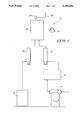
- FIG. 1 is a diagram of a portion of a system for carrying out methods in accordance with the invention.
- FIG. 2 is a diagrammatic and side elevational view of photochemical reaction chambers in accordance with the invention.
- FIG. 3 is a top, but diagrammatic, view of FIG. 2.
- FIG. 4 is a enlarged fragmentary sectional view of an upper portion of one of the photochemical chambers of FIG. 2.
- FIG. 5 is a further enlarged diagrammatic view of a liner utilized in the photochemical reaction chambers of FIG. 2.
- FIG. 6 is a diagram of a wet chemical scrubber utilized in accordance with the system and method of the invention.
- FIG. 7 is a fragmentary, cut-away view of an alternate embodiment system in accordance with the invention.
- FIG. 8 is a top view of the reaction chamber section of FIG. 7.
- FIG. 9 is an enlarged fragmentary view of an alternate embodiment reaction chamber and liner in accordance with the invention.
- FIG. 10 is a cross-section of another alternate embodiment reaction chamber liner in accordance with the invention.
- a method of photochemically oxidizing gaseous halogenated organic compounds comprises:
- the chamber comprises an elongated reaction chamber provided with internal sidewalls effectively lined with the dry porous cementitious and chemically sorbent material.
- sorbent material means a material which chemically or physically adsorbs or absorbs the gaseous oxidation products.
- an apparatus for photochemically oxidizing gaseous halogenated organic compounds comprises:
- reaction chamber having a gas inlet, internal sidewalls and a gas outlet;
- a source of ultraviolet light provided within and along the elongated reaction chamber to oxidize gaseous halogenated organic compounds fed to the reaction chamber into gaseous oxidation products;
- reaction chamber internal sidewalls comprising a dry porous cementitious and chemically sorbent material, the sorbent material being chemically reactive with the gaseous oxidation products to produce solid reaction products incorporated in the reaction chamber sidewalls.
- a removable reaction chamber liner for a photochemical oxidation reactor apparatus comprises:
- a support shell sized and shaped to be received internally within a photochemical oxidation reactor, the support shell having internal sidewalls which define a pathway for gaseous flow therethrough, the pathway being of sufficient size to receive a source of ultraviolet light sufficient to oxidize gaseous halogenated organic compounds fed to the reaction chamber into gaseous oxidation products;
- the sidewalls being lined with a dry porous cementitious and chemically sorbent material, the sorbent material being chemically reactive with the gaseous oxidation products to produce solid reaction products incorporated in the lined reaction chamber sidewalls.
- a method of producing such a liner comprises the following steps:
- FIG. 1 illustrates a mixing and charging system 10 for combining gaseous halogenated organic compounds and oxygen (typically ambient air) for feeding to reaction chambers for processing in accordance with the invention.
- a mixing and charging system 10 for combining gaseous halogenated organic compounds and oxygen (typically ambient air) for feeding to reaction chambers for processing in accordance with the invention.
- Such a system might include a storage tank 12 for the gaseous halogenated organic compounds to be treated and an air pump 14 for combining air with the gaseous halogenated organic compounds.
- Most any gaseous halogenated organic compounds are anticipated to be usable in accordance with the invention. However, those compounds identified in the "Background of the Invention" section of this document are the primary gaseous organic compounds with which the invention was designed and reduced to practice.
- Intake air (preferably filtered) would be pumped by air pump 14 to an air dehumidifier 16 for dehumidification.
- air dehumidifier 16 for dehumidification.
- H 2 O is removed from the intake air stream as possible.
- the methods of the invention would also function with H 2 O present, although at a much slower reaction rate.
- Gaseous halogenated organic compounds from tank 12 (preferably dried and de-oiled) and from intake air dehumidifier 16 are passed to a mixing chamber 18 through respective flow meters 22, 20. Pressure within mixing chamber 18 would be monitored by a pressure gauge 24, with feed of the mixed gases to the reaction chambers being regulated by a regulator 26.
- reaction mixture exiting tank 18 is provided such that there is from a 33% to 250% molar excess of O 2 as compared to the quantity of atoms which form the gaseous halogenated organic compound(s). Yet, photochemical oxidation will occur at the extremes of where there is a negligible quantity of O 2 or where the organic compounds are only present in part per million quantities. However, the efficiency and rate of conversion are expected to be considerably less.
- FIG. 1 illustrates but one system for selectively mixing desired quantities of oxygen and gaseous halogenated organic compounds to be treated.
- Alternate systems could of course be developed without departing from the principles and scope of the invention, which are intended to only be limited by the accompanying claims appropriately interpreted in accordance with the Doctrine of Equivalents.
- the invention is expected to have both large and small scale uses, such as for example in the air conditioning/refrigeration and computer chip industries.
- a typical small scale use in connection with one part of the air conditioning industry would be in a common automotive service station where Freon or mixed Freons are collected during routine auto air conditioning maintenance.
- the mixed gases exiting through regulator 26 from FIG. 1 can be fed via a line 28 (FIGS. 1 and 2) to a series of four photochemical reaction chambers 30, 32, 33 and 34.
- a source of ultraviolet light would be positioned within each of chambers 30, 32, 33 and 34, as will be described subsequently.
- Gas to be treated from line 28 would flow into the lower portion of chamber 30, as indicated by arrow 28 in FIG. 2.
- the gas mixture would be oxidized by the ultraviolet light source, with reacted and unreacted gas flowing from the upper end of chamber 30 through an interconnecting channel 35 to the top of chamber 32. Gases would flow down chamber 32 for continued reaction of the mixture and across an interconnecting channel 37 to the bottom of chamber 33.
- reacted and unreacted gases would flow up chamber 33 and across an interconnecting channel 39 to the top of chamber 34, and down chamber 34 to an outlet 41.
- a recirculation pump 36 and associated recycle control valve 38 can be provided for causing recycle of the reactant and reacted gases, as desired, for substantial oxidation of the halogenated organic compounds.
- Gaseous product would be fed through valve 38 to a wet chemical scrubber 40 for further capture or reaction therewithin. Thereafter, gas can be vented via a line 42 to the atmosphere or to another system for subsequent treatment, as desired.
- reaction chamber 30 has a gas inlet (FIG. 2) where line 28 enters, a gas outlet 46 defined in part by channel member 35, and effective internal sidewalls 45.
- a source of ultraviolet light 48 is provided within and along reaction chamber 30 to oxidize gaseous halogenated organic compounds fed thereto into gaseous oxidation products.
- Internal sidewalls 45 comprise a dry porous cementitious and chemically sorbent material which is chemically reactive with the gaseous oxidation products.
- reaction chamber 30 is comprised of an elongated stainless steel or other metal sleeve 50 having opposing male threaded ends 52. Only one threaded end 52 is shown in FIG. 4.
- a complementary metal female cap 54 threads to each end 52 of teflon sleeve 50.
- Sleeve 50 is provided with an internal coating 58 of a protective material, such as polytetrafluoroethylene. Metal would be rapidly corroded if exposed to the gaseous oxidation products.
- the polytetrafluoroethylene provides protection to the apparatus should gaseous oxidation products reach sleeve 50. The intent, however, is to prevent any exposure of gaseous oxidation products to lined sleeve 50.
- a removable reaction chamber liner 60 is provided immediately inwardly adjacent polytetrafluoroethylene coating 58 within chamber 30 for providing a gas/solid reaction between liner 60 and gaseous oxidation products the result to exposure to ultraviolet light source 48. More particularly, removable reaction chamber liner 60 is comprised of a support shell 62, preferably made of polytetrafluoroethylene, which is sized and shaped to be slidably and snugly received internally within polytetrafluoroethylene coated sleeve 50. In this manner removable liner 60, and all components forming apart thereof, is replaceable and potentially recyclable.
- Support shell 62 has internal side walls 64 which are coated with a lining 66 comprised of the dry porous cementitious and chemically sorbent material which is chemically reactive with the gaseous oxidation products, thereby producing solid reaction products incorporated into solid lining 66.
- the lining 66 effectively forms or comprises reaction chamber sidewalls 45 which are exposed to the gaseous oxidation products for a gas-solid phase reaction therewith.
- the composition and application of material 66 is described in more detail below.
- Support shell 62 with lining 66 defines a pathway 68 within elongated reactor chamber 30 for gaseous flow, and is of sufficient size to receive and retain ultraviolet light source 48. More particularly, support shell 62 has identical opposed female threaded ends. The illustrated upper end internally receives an externally male threaded end cap apparatus 71 which functions to retain ultraviolet light source 48 and prevent escape of any reactant and reacted gases. An identical end cap apparatus is received at the end opposite the FIG. 4 illustrated end.
- End cap apparatus 71 includes a donut shaped component 70 having a threaded central opening provided therethrough, and having external threads which thread relative to threaded end 52 of support shell 62.
- An elongated and threaded female compression component 72 threads internally to the central opening provided in first donut 70. Compression component 72 projects upwardly relative to first donut 70.
- a central opening, inwardly tapered from the top, is provided internally through compression component 72.
- a wedge shaped hollow male compression ring 76 is slidably received within the tapered central compression component 72 opening.
- An elongated ultraviolet lamp 74 which defines ultraviolet light source 48, extends slidably through the central opening in compression component 72 and within compression ring 76.
- Lamp 74 preferably produces ultraviolet light in the wavelength of approximately 185 nanometers.
- An example would be 64-inch long 65 watt quartz enveloped ultraviolet light tubes which are commercially available from, for example, Atlantic Ultraviolet Corporation of Long Island, N.Y.
- a compression cap 79 threads to compression component 72 and engages ring 76 for creating a compression seal against lamp 76.
- a cross member cutout 77 is provided through support shell 62 and lining 66 as shown for alignment with cross piece 35.
- Cross piece 35 is shown lined with polytetrafluoroethylene layer 59.
- the cross pieces are also preferably provided with separate, snug-fitting replaceable polytetrafluoroethylene shells lined with material 66 for reaction with the oxidized reaction products.
- the cross pieces can be constructed to connect with the associated sleeve 50 by any suitable means, such as with pipe unions, flange and bolt covers, etc.
- a sensor is interposed between internal sidewall 64 of support shell 62 and dry porous cementitious material 66.
- the sensor is comprised of a material which is reactive with the gaseous oxidation products upon exhaustion and degradation of the overlying dry porous cementitious chemically sorbent material of liner 66.
- the sensor is comprised of a strip of metal tape 90 which extends along the length of shell 60 between sidewall 64 and beneath lining 66.
- An example material for tape 90 would be copper.
- Conductive leads such as lead 92, are connected to opposite ends of tape strip 90. Such leads would be connected to a resistance meter which would provide a small source of monitored electric current. Upon complete corrosion through and across strip 90, infinite resistance would be registered clearly indicating that the gaseous oxidation products had permeated the spent lining 66.
- a bimetal circuit material could be provided that would generate a milliamp current which could be monitored by an amp meter. Changes in amperage would be indicative of the presence of gaseous oxidation products which have permeated lining 66. Any such indication would indicate that replacement of replaceable liner 60 was in order.
- support shell 62 might be recycled by stripping spent cementitious material 66 therefrom, and reusing shell 62 for another application of such material.
- a similar sensor circuit could be positioned between shell 62 and lining 58 of sleeve 50 in an effort to detect any gaseous oxidation products which would indicate faulty operation.
- a sensor would preferably be provided in association with cross piece 35.
- reaction chamber 30a and associated liner 60a is shown and described with reference to FIG. 9. Such construction is analogous to the first described embodiment, but replaces the threading of various components with clamping action.
- sleeve 50a is provided with a pair of external clamp retainers 130.
- a modified cap 54a is fitted with an opposing pair of external clamps 132 which engage with retainers 130.
- Cap 54a includes an annular groove 134 sized to receive the end of sleeve 50a.
- a gasket 136 is provided in groove 134 for sealing engagement relative to cap 54a and sleeve 50a.
- Cap 54a is also provided with a central projecting cylinder 138 having an opening 140 therein which receives the end of ultraviolet light 74.
- a conventional spring biased electrical connection 142 is provided at the base of cylinder 138.
- An external post 144 would be connected to a suitable power source for energizing light 74.
- Support shell 62a of lining component 60a is provided with blunt non-threaded ends.
- a compression component 70a is clamped in place against the blunt end of shell 60a by cap 54a, as shown.
- Component 70a is provided with a central conical opening 146 which receives a conical compression insert 76a.
- Central projecting cylinder 138 of cap 54a is sized and shaped to provide a suitable downward clamping force against insert 76a for retaining and sealing relative to light 74 when clamps 132 engages clamp retainers 130.
- FIG. 10 illustrates but one alternate example for sealing the end of a reaction chamber. Alternate methods could of course be used, for example, draw clamps, overcenter cams, a flange with bolt circle, tie rods, collet and lock ring, etc.
- gaseous halogenated organic compounds fed to the reaction chamber include chlorocarbons, fluorocarbons, chlorofluorocarbons and hydrochlorofluorocarbons
- typical gaseous oxidation products from HFC and CFC exposure to ultraviolet light are expected to include Cl 2 , F 2 , C x O y F z , C x O y Cl z , HCl and HF, among potential others.
- the dry porous cementitious material of layer or lining 66 preferably comprises a calcium based cement having induced porosity to maximize available surface area.
- the calcium based cement as solidified will comprise a metastable compound of CaO•Al 2 O 3 •xH 2 O, where "x" may be anywhere from 1 to 6.
- the calcium based cement will be produced by having added basic constituents such as Ca(OH) 2 and Mg(OH) 2 or mixtures thereof.
- the gaseous organic compounds being oxidized include fluorine and chlorine containing compounds
- the ultraviolet light will oxidize the feed material to highly reactive fluorine and chlorine containing radicals which will produce solid reaction products within lining 66 comprising CaF 2 , CaFCl, CaCl 2 , MgF 2 , MgFCl, or MgCl 2 , and perhaps other solid reaction products.
- the preferred dry mixture for making the cementitious material comprises from about 20% to 33% by weight of an alumina based CaO cement.
- added CaO is provided up to an additional 10 weight per cent of the dry mixture.
- added Ca(OH) 2 , Mg(OH) 2 or mixtures thereof is provided up to 25% by weight of the dry mixture.
- the dry mixture also preferably includes alumina aggregate at between 50% to 70% by weight.
- a foaming agent is also added in an effective mount to impart foaming in the resultant slurry and corresponding porosity in the hardened material.
- the intent is to produce a porous composite having a density from about 0.5 g/cm 2 to about 3 g/cm 2 .
- Elemental aluminum is one example of a material which will induce such porosity.
- the resultant product provides a porous, basic constituent for reacting with the largely acidic radical oxidation products produced by the photooxidation.
- the added CaO, Ca(OH) 2 or Mg(OH) 2 provide added basic components for reaction and neutralization of the oxidized products produced by the ultraviolet light.
- Preferably the amount of silicon in the form of SiO 2 or others in the cementitious material is minimized in an effort to avoid formation of hazardous gaseous silicon chlorides or silicon fluorides.
- a lining in accordance with the above parameters was produced from the following dry powder composition, by weight:
- the dry powder composition was mixed with water in a weight ratio of water to dry mixture of 1.65:1.
- the weight ratio of water to dry mixture is from about 1.5:1 to 1.65:1.
- the dry mixture and water are then thoroughly mixed into a slurry and then spun internally onto a spinning support shell.
- a support tube spun at between 50 to 100 rpms was internally coated by applying the slurry with a syringe to provide a 5 to 10 millimeter thick layer.
- the tube was allowed to spin for approximately one hour after application until the material adequately set, and then the spinning was stopped.
- the tube was then exposed to steam for approximately 24 hours to maximize the amount of hydrated water incorporated in the finished lining.
- the tube was dried 100° C. for and additional 25 hours in the absence of any water vapor to fully cure the lining.
- the invention was reduced to practice utilizing a gas mixture of gaseous halogenated organic material (5% by volume) and ambient air (95% by volume) which was oxidized by a 184.9 nanometer ultraviolet light source.
- the major reaction product peak was identified as COF 2 .
- a larger number of other yet unidentified peaks by chromatography were also developed.
- none of these peaks were observed by gas chromatography, indicating that chemical reaction or incorporation into the lining had occurred.
- the effects of the photochemical oxidation process on the dry chemical lining were evaluated using scanning electron microscopy (SEM) and semi-quantitative energy dispersive X-ray spectroscopy (EDXS) elemental analysis.
- SEM scanning electron microscopy
- EDXS semi-quantitative energy dispersive X-ray spectroscopy
- the SEM evaluations of dry liners before and after exposure demonstrate observable changes in the crystalline structure of the dry chemical liner. Specifically in most all cases, the Ca(OH) 2 crystals observed before exposure could not be observed after exposure.
- the hexagonal CaO.Al 2 O 3 plates also demonstrated substantial change in shape.
- the EDXS evaluation of the material indicated a significant increase in elemental chlorine after exposure. Elemental fluorine is something which is not observable by EDXS, and accordingly could not be observed.
- wet chemical scrubber 40 is provided to catch any gaseous oxidation products which pass through the reaction chambers without reacting with the liner side walls.
- a more detailed example of a preferred scrubber is indicated generally by reference numeral 100 in FIG. 6.
- Scrubber 100 is comprised of a enclosed tank 102 which retains a quantity of an alkaline solution 104.
- Solution 104 preferably comprises a 0.1-5.0 molar solution of, for example, Ca(OH) 2 , Na(OH) 2 , Mg(OH) 2 , NH 3 (OH) 2 , or mixtures thereof, to provide a pH of approximately 11-13.
- Exhaust gases are fed to scrubber 100 through a line 112 which passes through a check valve 114.
- a suction pressure pump (not shown) is provided upstream of valve 114 to assure complete evacuation of the reaction chambers.
- Check valve 114 prevents back flow of any fluid into the photochemical reaction chambers.
- Line 112 is fed to a looped line 110 through which alkaline solution 104 in tank 102 is pumped by a pump 108. Such provides a pressure drop in line 110 where it meets with line 112, thereby drawing the exhaust gases into the scrubber.
- the fluid emitted into alkaline solution 104 from line 110 facilitates intermixing of the alkaline solution and gas supplied thereto.
- the gaseous products fed to scrubber 100 are expected to include COF 2 , COClF, F 2 , Cl 2 , ClO, HCl, HF, and potentially any unreacted gaseous halogenated organic compounds. All of such components, except the gaseous halogenated organic compounds, are essentially reacted with either the linings 66 or retained in alkaline solution 104 of reaction in scrubber 100.
- Gas exiting tank 102 passes through a vapor trap and return 101.
- a pH monitor 103 is utilized to monitor pH of solution 104.
- FIGS. 7 and 8 illustrate a cooling jacket 122 provided about reaction chambers 30, 32, 33 and 34 which are here surrounded by a fluid tight cooling jacket 122.
- Cooling jacket 122 receives a cooling fluid through orifice 126 and emits heated fluid through orifice 128 for cooling the reaction chambers.
- An isolated central tube 124 (FIG. 8) as well passes through jacket 122. Ambient air or some other fluid is preferably blown through tube 124 for added heat dissipation.
- Chamber 32b comprises an extruded sleeve 50b, preferably comprised of polytetrafluoroethylene, having inward projecting components 63b.
- a central opening 59b at the end of sleeve 50b is provided for retaining an ultraviolet light source.
- Components 63b define elongated slots or cavities which retain a plurality of discrete elongated segments 65b which are comprised of the dry porous cementitious and chemically sorbent material. As illustrated, projecting components 63b retain segments 65b in juxtaposition to define effective internal reaction chamber sidewalls 45b which react with the gaseous oxidation products.
- Segments 65b would be separately fabricated and then slid into the slots or cavities. The segments would therefore also be replaceable. Alternate constructions could of course be utilized without departing from the principles and scope of the invention. By way of example only, segments could be provided in the form of rods or other shapes to effectively provide a lining for reaction with the gaseous oxidation products.
- the control of the stoichiometric relationship between the halogenated organic compounds and oxygen could be controlled through any number of means.
- One example would be to start with an evacuated chamber use an absolute manometer to regulate the partial pressure of each component of the mixture.
- An alternative method would be to use a dedicated infrared spectrometer attached to a computer monitored operating valving system that would adjust the concentration of the halogenated organic compounds and oxygen to predetermine concentrations.
- Another alternative would be to use a gas chromatograph in a similar manner. Other monitoring/control systems could of course be utilized.
- a computer activated or manual valve could be opened that would allow the photochemical reaction chambers to be charged with the premixed gases.
- This charging process could be enhanced by having a reduced pressure in the photochemical reactor and a slightly elevated pressure in the premixing chamber.
- the scrubber unit is preferably provided with an aspirator vacuum line (as described above), which could also be attached to the reaction chamber exhaust line.
- the reaction chamber exhaust line would be closed by a valve while the gas mixture was being treated and opened upon determination that halogenated organic compounds were no longer present in the chamber.
- the in situ determination of halogenated organic compound concentration during treatment could also be accomplished by several instrumental methods as well as by predetermined rates of destruction values.
- the preferred method is expected to utilize an instrumental method that monitors the disappearance of the halogenated organic compounds during reaction.
- a dedicated infrared spectrometer would probably function well in this capacity although other instrumental controls could easily be substituted.
- This system of monitoring the reaction process should also save, either to a computer or hard copy, the record of the reaction for environmental monitoring concerns.
- the wet chemical wash system is also envisioned as being monitored.
- the preferred method would be as described above by using an in situ pH electrodes. As long as the pH of the basic solutions remain above 7.0, they would still be effective.
- a feedback loop should notify the operator and insure that no additional operation of the device is possible until the pH has been returned to establish parameters. This will insure against any unreacted harmful gases passing through the scrubber system.
- Two additional monitoring systems that are capable of preventing operation of the device are envisioned.
- One of these is the previously described resistance circuit designed into the dry chemical liners. Upon failure of this monitoring circuit, the chemical liner may be considered exhausted and no longer capable of protecting the reaction chamber walls.
- This chemical activity monitor is envisioned as being monitored by computer and capable of preventing operation of the reaction chambers when not within specified parameters.
- the final control system envisioned will monitor the circuitry of the UV lamps. Should a lamp or series of lamps fail, this monitor would either compensate by increasing time of exposure of gases to the reaction chambers, or prevent operation of the photochemical reactor.
Landscapes
- Chemical & Material Sciences (AREA)
- Engineering & Computer Science (AREA)
- Chemical Kinetics & Catalysis (AREA)
- Environmental & Geological Engineering (AREA)
- Health & Medical Sciences (AREA)
- Biomedical Technology (AREA)
- Analytical Chemistry (AREA)
- General Chemical & Material Sciences (AREA)
- Oil, Petroleum & Natural Gas (AREA)
- General Health & Medical Sciences (AREA)
- Electromagnetism (AREA)
- Physics & Mathematics (AREA)
- Toxicology (AREA)
- Organic Chemistry (AREA)
- Treating Waste Gases (AREA)
- Physical Or Chemical Processes And Apparatus (AREA)
- Solid-Sorbent Or Filter-Aiding Compositions (AREA)
- Organic Low-Molecular-Weight Compounds And Preparation Thereof (AREA)
- Fire-Extinguishing Compositions (AREA)
Priority Applications (11)
| Application Number | Priority Date | Filing Date | Title |
|---|---|---|---|
| US07/843,422 US5260036A (en) | 1992-02-27 | 1992-02-27 | Method and apparatus for use in photochemically oxidizing gaseous halogenated organic compounds |
| AU37747/93A AU663775C (en) | 1992-02-27 | 1993-02-18 | Method and apparatus for use in photochemically oxidizing gaseous halogenated organic compounds |
| ES93906975T ES2121998T3 (es) | 1992-02-27 | 1993-02-18 | Metodo y aparato para la oxidacion fotoquimica de compuestos organicos halogenados gaseosos. |
| DE69321825T DE69321825T2 (de) | 1992-02-27 | 1993-02-18 | Verfahren und vorrichtung zur photochemischen oxidation von gasförmigen, halogenierten, organischen verbindungen |
| PCT/US1993/001475 WO1993016761A1 (en) | 1992-02-27 | 1993-02-18 | Method and apparatus for use in photochemically oxidizing gaseous halogenated organic compounds |
| EP93906975A EP0627944B1 (de) | 1992-02-27 | 1993-02-18 | Verfahren und vorrichtung zur photochemischen oxidation von gasförmigen, halogenierten, organischen verbindungen |
| JP5514962A JPH07509381A (ja) | 1992-02-27 | 1993-02-18 | 気状ハロゲン化有機化合物を光学的酸化するのに使用するための方法及び装置 |
| AT93906975T ATE172645T1 (de) | 1992-02-27 | 1993-02-18 | Verfahren und vorrichtung zur photochemischen oxidation von gasförmigen, halogenierten, organischen verbindungen |
| CA002131006A CA2131006A1 (en) | 1992-02-27 | 1993-02-18 | Method and apparatus for use in photochemically oxidizing gaseous halogenated organic compounds |
| US08/078,611 US5374404A (en) | 1992-02-27 | 1993-06-15 | Method and apparatus for use in photochemically oxidizing gaseous halogenated organic compounds |
| US08/078,901 US5397552A (en) | 1992-02-27 | 1993-06-15 | Method and apparatus for use in photochemically oxidizing gaseous organic compounds |
Applications Claiming Priority (1)
| Application Number | Priority Date | Filing Date | Title |
|---|---|---|---|
| US07/843,422 US5260036A (en) | 1992-02-27 | 1992-02-27 | Method and apparatus for use in photochemically oxidizing gaseous halogenated organic compounds |
Related Child Applications (2)
| Application Number | Title | Priority Date | Filing Date |
|---|---|---|---|
| US08/078,901 Continuation-In-Part US5397552A (en) | 1992-02-27 | 1993-06-15 | Method and apparatus for use in photochemically oxidizing gaseous organic compounds |
| US08/078,611 Continuation US5374404A (en) | 1992-02-27 | 1993-06-15 | Method and apparatus for use in photochemically oxidizing gaseous halogenated organic compounds |
Publications (1)
| Publication Number | Publication Date |
|---|---|
| US5260036A true US5260036A (en) | 1993-11-09 |
Family
ID=25289930
Family Applications (2)
| Application Number | Title | Priority Date | Filing Date |
|---|---|---|---|
| US07/843,422 Expired - Fee Related US5260036A (en) | 1992-02-27 | 1992-02-27 | Method and apparatus for use in photochemically oxidizing gaseous halogenated organic compounds |
| US08/078,611 Expired - Fee Related US5374404A (en) | 1992-02-27 | 1993-06-15 | Method and apparatus for use in photochemically oxidizing gaseous halogenated organic compounds |
Family Applications After (1)
| Application Number | Title | Priority Date | Filing Date |
|---|---|---|---|
| US08/078,611 Expired - Fee Related US5374404A (en) | 1992-02-27 | 1993-06-15 | Method and apparatus for use in photochemically oxidizing gaseous halogenated organic compounds |
Country Status (8)
| Country | Link |
|---|---|
| US (2) | US5260036A (de) |
| EP (1) | EP0627944B1 (de) |
| JP (1) | JPH07509381A (de) |
| AT (1) | ATE172645T1 (de) |
| CA (1) | CA2131006A1 (de) |
| DE (1) | DE69321825T2 (de) |
| ES (1) | ES2121998T3 (de) |
| WO (1) | WO1993016761A1 (de) |
Cited By (22)
| Publication number | Priority date | Publication date | Assignee | Title |
|---|---|---|---|---|
| US5370845A (en) * | 1991-08-30 | 1994-12-06 | Alliant Techsystems | Process and apparatus for photolytic degradation of explosives |
| US5401474A (en) * | 1990-04-13 | 1995-03-28 | Peroxidation Systems, Inc. | Modular self-cleaning oxidation chamber |
| US5468459A (en) * | 1995-02-28 | 1995-11-21 | The Boc Group, Inc. | Gas stream treatment method for removing per-fluorocarbons |
| US5531969A (en) * | 1991-10-19 | 1996-07-02 | Deutsche Forschungsanstalt Fuer Luft- Und Raumfahrt E.V. | Solar energy installation for chemical conversions |
| US5567621A (en) * | 1993-07-14 | 1996-10-22 | Shimadzu Corporation | Method of and apparatus for analyzing nitrogen compound and phosphorus compound contained in water |
| US5714665A (en) * | 1995-02-23 | 1998-02-03 | The Tokyo Electric Power Co., Inc. | Method and apparatus for the decomposition and re-use-as-resource treatment of ozone layer-depleting substances by application of UV light |
| US5835840A (en) * | 1995-09-06 | 1998-11-10 | Universal Air Technology | Photocatalytic system for indoor air quality |
| US5933702A (en) * | 1995-09-06 | 1999-08-03 | Universal Air Technology | Photocatalytic air disinfection |
| US5942109A (en) * | 1996-12-05 | 1999-08-24 | Oase-Pumpen Wuebker Soehne Gmbh & Co. | Apparatus for the treatment of liquids |
| US5979054A (en) * | 1995-09-29 | 1999-11-09 | Process Technologies, Inc. | Method of forming a sidewall for a reactor for oxidizing volatile or semi-volatile organic compounds |
| US5993738A (en) * | 1997-05-13 | 1999-11-30 | Universal Air Technology | Electrostatic photocatalytic air disinfection |
| US6004667A (en) * | 1994-06-30 | 1999-12-21 | Shinshu Ceramics Company, Ltd. | Low temperature melt injected anti-microbial films, articles containing such films and methods of manufacture and use thereof |
| US20020189929A1 (en) * | 1998-12-16 | 2002-12-19 | Kinya Kato | Apparatus for decomposing gaseous aliphatic hydrocarbon halide compounds |
| US20030089594A1 (en) * | 2001-11-12 | 2003-05-15 | Kinya Kato | Method of treating substance to be degraded and its apparatus |
| US20030089595A1 (en) * | 2001-11-12 | 2003-05-15 | Kinya Kato | Method and apparatus for processing substances to be decomposed |
| US6599431B2 (en) | 2000-06-16 | 2003-07-29 | Canon Kabushiki Kaisha | Purifying apparatus for contaminated water and ground water and method thereof |
| US20030164286A1 (en) * | 1998-06-22 | 2003-09-04 | Canon Kabushiki Kaisha | Apparatus for decomposing halogenated aliphatic hydrocarbon compounds or aromatic compounds |
| US20040005715A1 (en) * | 2001-12-13 | 2004-01-08 | The University Of Wyoming Research Corporation D/B/A Western Research Institute | Volatile organic compound sensor system |
| US20050034971A1 (en) * | 2000-11-21 | 2005-02-17 | Cannon Kabushiki Kaisha | Method and apparatus for decomposing pollutants |
| US20060010991A1 (en) * | 2004-07-15 | 2006-01-19 | Pdc Facilities, Inc. | Liner for a flow meter |
| US20080035227A1 (en) * | 2005-07-14 | 2008-02-14 | Pdc Facilities, Inc. | Liner for a flow meter |
| CN109790051A (zh) * | 2016-08-30 | 2019-05-21 | 日机装株式会社 | 紫外光杀菌装置 |
Families Citing this family (5)
| Publication number | Priority date | Publication date | Assignee | Title |
|---|---|---|---|---|
| US5397552A (en) * | 1992-02-27 | 1995-03-14 | Process Technologies, Inc. | Method and apparatus for use in photochemically oxidizing gaseous organic compounds |
| JPH0859210A (ja) * | 1994-08-24 | 1996-03-05 | Ebara Corp | オゾン発生装置 |
| KR20000017687A (ko) * | 1999-04-30 | 2000-04-06 | 최수현 | SOx/NOx동시처리또는단일성분분리처리용광촉매박막형광화학반응시스템 |
| JP6118593B2 (ja) * | 2013-03-12 | 2017-04-19 | 日立造船株式会社 | 両端開閉自在な耐圧反応器 |
| JP2014233678A (ja) * | 2013-06-03 | 2014-12-15 | ウシオ電機株式会社 | ガス処理装置 |
Citations (32)
| Publication number | Priority date | Publication date | Assignee | Title |
|---|---|---|---|---|
| US2998308A (en) * | 1958-03-24 | 1961-08-29 | Joseph P Ruth | Gas treating apparatus |
| US3674666A (en) * | 1970-08-19 | 1972-07-04 | Richard N Foster | Enhancing reaction rates |
| US3773044A (en) * | 1971-03-10 | 1973-11-20 | R Wallace | Chemical breathing apparatus with alarm device |
| US3902485A (en) * | 1974-02-08 | 1975-09-02 | Richard A Wallace | Chemically activated warning system |
| US3977952A (en) * | 1973-08-16 | 1976-08-31 | C. F. Spiess & Sohn | Process for decomposing carbon-containing compounds |
| US4045316A (en) * | 1975-05-27 | 1977-08-30 | Shintech Incorporated | Photochemical process for decontaminating gaseous or vaporous streams |
| US4129418A (en) * | 1978-02-21 | 1978-12-12 | General Electric Company | Discriminating halogen sensor |
| US4144152A (en) * | 1978-03-27 | 1979-03-13 | Atlantic Research Corporation | Dehalogenation of halogenated compounds |
| US4146887A (en) * | 1977-08-05 | 1979-03-27 | American Optical Corporation | Respirator cartridge end-of-service life indicator |
| US4210503A (en) * | 1975-12-31 | 1980-07-01 | Exxon Research & Engineering Co. | Emission control method and system |
| US4399686A (en) * | 1980-02-21 | 1983-08-23 | Engstrom Medical Ab | Gas detector |
| US4468376A (en) * | 1982-05-03 | 1984-08-28 | Texaco Development Corporation | Disposal process for halogenated organic material |
| US4499054A (en) * | 1981-08-31 | 1985-02-12 | Tokyo Shibaura Denki Kabushiki Kaisha | Cation emission type halogenated hydrocarbon gas detecting element |
| US4668489A (en) * | 1984-01-30 | 1987-05-26 | Efb Inc. | Method for treating gas streams |
| US4694179A (en) * | 1986-05-27 | 1987-09-15 | Lew Hyok S | Symbiotic filter-sterilizer |
| US4780287A (en) * | 1984-07-03 | 1988-10-25 | Ultrox International | Decomposition of volatile organic halogenated compounds contained in gases |
| US4786484A (en) * | 1987-02-03 | 1988-11-22 | Sanitech, Inc. | Process for absorbing toxic gas |
| US4847594A (en) * | 1988-03-28 | 1989-07-11 | Transducer Research, Inc. | Sensor for detecting the exhaustion of an adsorbent bed |
| US4892712A (en) * | 1987-09-04 | 1990-01-09 | Nutech Energy Systems Inc. | Fluid purification |
| US4935212A (en) * | 1988-12-13 | 1990-06-19 | Man Technologie Gmbh | Method of decomposing organic halogen compounds in gaseous phase |
| US4937065A (en) * | 1985-05-11 | 1990-06-26 | Nukem Gmbh | Process for the chemical-thermal degradation of haolgenated hydrocarbons |
| US4941957A (en) * | 1986-10-22 | 1990-07-17 | Ultrox International | Decomposition of volatile ogranic halogenated compounds contained in gases and aqueous solutions |
| US4954320A (en) * | 1988-04-22 | 1990-09-04 | The United States Of America As Represented By The Secretary Of The Army | Reactive bed plasma air purification |
| US4971687A (en) * | 1987-11-06 | 1990-11-20 | John B. Knight, Jr. | Apparatus for water treatment |
| US4983366A (en) * | 1987-09-21 | 1991-01-08 | Degussa Aktiengesellschaft | Method for the catalytic conversion of waste gases containing hydrocarbon, halogenated hydrocarbon and carbon monoxide |
| US4990311A (en) * | 1987-03-20 | 1991-02-05 | Tohkai Kogyo Co., Ltd. | Deodorizing apparatus and method |
| US5032241A (en) * | 1987-09-04 | 1991-07-16 | Nutech Energy Systems Inc. | Fluid purification |
| US5035784A (en) * | 1987-07-27 | 1991-07-30 | Wisconsin Alumni Research Foundation | Degradation of organic chemicals with titanium ceramic membranes |
| US5045288A (en) * | 1989-09-15 | 1991-09-03 | Arizona Board Of Regents, A Body Corporate Acting On Behalf Of Arizona State University | Gas-solid photocatalytic oxidation of environmental pollutants |
| US5055266A (en) * | 1984-03-02 | 1991-10-08 | Arch Development Corporation | Method for detecting toxic gases |
| US5069885A (en) * | 1990-04-23 | 1991-12-03 | Ritchie David G | Photocatalytic fluid purification apparatus having helical nontransparent substrate |
| US5126111A (en) * | 1990-12-05 | 1992-06-30 | Nutech Energy Systems Inc. | Fluid purification |
Family Cites Families (8)
| Publication number | Priority date | Publication date | Assignee | Title |
|---|---|---|---|---|
| US4454099A (en) * | 1982-05-06 | 1984-06-12 | Phillips Petroleum Company | Sorbent bases treated with organic halides and their use to remove acidic substances from gas mixtures |
| SE452255B (sv) * | 1984-10-23 | 1987-11-23 | Skf Steel Eng Ab | Sett for rening av avgaser fran giftiga klorforeningar och/eller tyngre kolveten samt anordning for genomforande av settet |
| JPH0611378B2 (ja) * | 1988-10-18 | 1994-02-16 | 工業技術院長 | 揮発性有機塩素化合物の除去方法 |
| US5024688A (en) * | 1988-11-30 | 1991-06-18 | Fujikura Ltd. | Method for producing carbon-coated optical fiber |
| DE3907670A1 (de) * | 1989-03-09 | 1990-09-13 | Hartmut Dr Hoffmann | Vorrichtung und verfahren zur bestrahlung von chemischen substanzen und verbindungen |
| DE3913968A1 (de) * | 1989-04-27 | 1989-11-09 | Asea Brown Boveri | Verfahren zur behandlung von organischen abluftinhaltstoffen |
| US5141636A (en) * | 1991-01-08 | 1992-08-25 | United States Of America As Represented By The Administrator, National Aeronautics And Space Administration | Purification system |
| JP2989700B2 (ja) * | 1991-10-22 | 1999-12-13 | 芝浦メカトロニクス株式会社 | 半導体樹脂ばり除去装置 |
-
1992
- 1992-02-27 US US07/843,422 patent/US5260036A/en not_active Expired - Fee Related
-
1993
- 1993-02-18 JP JP5514962A patent/JPH07509381A/ja active Pending
- 1993-02-18 EP EP93906975A patent/EP0627944B1/de not_active Expired - Lifetime
- 1993-02-18 AT AT93906975T patent/ATE172645T1/de not_active IP Right Cessation
- 1993-02-18 WO PCT/US1993/001475 patent/WO1993016761A1/en not_active Ceased
- 1993-02-18 DE DE69321825T patent/DE69321825T2/de not_active Expired - Fee Related
- 1993-02-18 CA CA002131006A patent/CA2131006A1/en not_active Abandoned
- 1993-02-18 ES ES93906975T patent/ES2121998T3/es not_active Expired - Lifetime
- 1993-06-15 US US08/078,611 patent/US5374404A/en not_active Expired - Fee Related
Patent Citations (32)
| Publication number | Priority date | Publication date | Assignee | Title |
|---|---|---|---|---|
| US2998308A (en) * | 1958-03-24 | 1961-08-29 | Joseph P Ruth | Gas treating apparatus |
| US3674666A (en) * | 1970-08-19 | 1972-07-04 | Richard N Foster | Enhancing reaction rates |
| US3773044A (en) * | 1971-03-10 | 1973-11-20 | R Wallace | Chemical breathing apparatus with alarm device |
| US3977952A (en) * | 1973-08-16 | 1976-08-31 | C. F. Spiess & Sohn | Process for decomposing carbon-containing compounds |
| US3902485A (en) * | 1974-02-08 | 1975-09-02 | Richard A Wallace | Chemically activated warning system |
| US4045316A (en) * | 1975-05-27 | 1977-08-30 | Shintech Incorporated | Photochemical process for decontaminating gaseous or vaporous streams |
| US4210503A (en) * | 1975-12-31 | 1980-07-01 | Exxon Research & Engineering Co. | Emission control method and system |
| US4146887A (en) * | 1977-08-05 | 1979-03-27 | American Optical Corporation | Respirator cartridge end-of-service life indicator |
| US4129418A (en) * | 1978-02-21 | 1978-12-12 | General Electric Company | Discriminating halogen sensor |
| US4144152A (en) * | 1978-03-27 | 1979-03-13 | Atlantic Research Corporation | Dehalogenation of halogenated compounds |
| US4399686A (en) * | 1980-02-21 | 1983-08-23 | Engstrom Medical Ab | Gas detector |
| US4499054A (en) * | 1981-08-31 | 1985-02-12 | Tokyo Shibaura Denki Kabushiki Kaisha | Cation emission type halogenated hydrocarbon gas detecting element |
| US4468376A (en) * | 1982-05-03 | 1984-08-28 | Texaco Development Corporation | Disposal process for halogenated organic material |
| US4668489A (en) * | 1984-01-30 | 1987-05-26 | Efb Inc. | Method for treating gas streams |
| US5055266A (en) * | 1984-03-02 | 1991-10-08 | Arch Development Corporation | Method for detecting toxic gases |
| US4780287A (en) * | 1984-07-03 | 1988-10-25 | Ultrox International | Decomposition of volatile organic halogenated compounds contained in gases |
| US4937065A (en) * | 1985-05-11 | 1990-06-26 | Nukem Gmbh | Process for the chemical-thermal degradation of haolgenated hydrocarbons |
| US4694179A (en) * | 1986-05-27 | 1987-09-15 | Lew Hyok S | Symbiotic filter-sterilizer |
| US4941957A (en) * | 1986-10-22 | 1990-07-17 | Ultrox International | Decomposition of volatile ogranic halogenated compounds contained in gases and aqueous solutions |
| US4786484A (en) * | 1987-02-03 | 1988-11-22 | Sanitech, Inc. | Process for absorbing toxic gas |
| US4990311A (en) * | 1987-03-20 | 1991-02-05 | Tohkai Kogyo Co., Ltd. | Deodorizing apparatus and method |
| US5035784A (en) * | 1987-07-27 | 1991-07-30 | Wisconsin Alumni Research Foundation | Degradation of organic chemicals with titanium ceramic membranes |
| US4892712A (en) * | 1987-09-04 | 1990-01-09 | Nutech Energy Systems Inc. | Fluid purification |
| US5032241A (en) * | 1987-09-04 | 1991-07-16 | Nutech Energy Systems Inc. | Fluid purification |
| US4983366A (en) * | 1987-09-21 | 1991-01-08 | Degussa Aktiengesellschaft | Method for the catalytic conversion of waste gases containing hydrocarbon, halogenated hydrocarbon and carbon monoxide |
| US4971687A (en) * | 1987-11-06 | 1990-11-20 | John B. Knight, Jr. | Apparatus for water treatment |
| US4847594A (en) * | 1988-03-28 | 1989-07-11 | Transducer Research, Inc. | Sensor for detecting the exhaustion of an adsorbent bed |
| US4954320A (en) * | 1988-04-22 | 1990-09-04 | The United States Of America As Represented By The Secretary Of The Army | Reactive bed plasma air purification |
| US4935212A (en) * | 1988-12-13 | 1990-06-19 | Man Technologie Gmbh | Method of decomposing organic halogen compounds in gaseous phase |
| US5045288A (en) * | 1989-09-15 | 1991-09-03 | Arizona Board Of Regents, A Body Corporate Acting On Behalf Of Arizona State University | Gas-solid photocatalytic oxidation of environmental pollutants |
| US5069885A (en) * | 1990-04-23 | 1991-12-03 | Ritchie David G | Photocatalytic fluid purification apparatus having helical nontransparent substrate |
| US5126111A (en) * | 1990-12-05 | 1992-06-30 | Nutech Energy Systems Inc. | Fluid purification |
Non-Patent Citations (2)
| Title |
|---|
| Federal Laboratory Technology Application Assessment, "Laser Controlled Decomposition of Chlorofluorocarbons". |
| Federal Laboratory Technology Application Assessment, Laser Controlled Decomposition of Chlorofluorocarbons . * |
Cited By (36)
| Publication number | Priority date | Publication date | Assignee | Title |
|---|---|---|---|---|
| US5401474A (en) * | 1990-04-13 | 1995-03-28 | Peroxidation Systems, Inc. | Modular self-cleaning oxidation chamber |
| US5516970A (en) * | 1991-08-30 | 1996-05-14 | Global Environmental Solutions, Inc. | Process and apparatus for photolytic degradation of explosives |
| US5524545A (en) * | 1991-08-30 | 1996-06-11 | Global Environmental Solutions, Inc. | Process and apparatus for photolytic degradation of explosives |
| US5370845A (en) * | 1991-08-30 | 1994-12-06 | Alliant Techsystems | Process and apparatus for photolytic degradation of explosives |
| US5531969A (en) * | 1991-10-19 | 1996-07-02 | Deutsche Forschungsanstalt Fuer Luft- Und Raumfahrt E.V. | Solar energy installation for chemical conversions |
| US5567621A (en) * | 1993-07-14 | 1996-10-22 | Shimadzu Corporation | Method of and apparatus for analyzing nitrogen compound and phosphorus compound contained in water |
| US6004667A (en) * | 1994-06-30 | 1999-12-21 | Shinshu Ceramics Company, Ltd. | Low temperature melt injected anti-microbial films, articles containing such films and methods of manufacture and use thereof |
| US5714665A (en) * | 1995-02-23 | 1998-02-03 | The Tokyo Electric Power Co., Inc. | Method and apparatus for the decomposition and re-use-as-resource treatment of ozone layer-depleting substances by application of UV light |
| US5468459A (en) * | 1995-02-28 | 1995-11-21 | The Boc Group, Inc. | Gas stream treatment method for removing per-fluorocarbons |
| US5835840A (en) * | 1995-09-06 | 1998-11-10 | Universal Air Technology | Photocatalytic system for indoor air quality |
| US5933702A (en) * | 1995-09-06 | 1999-08-03 | Universal Air Technology | Photocatalytic air disinfection |
| US5979054A (en) * | 1995-09-29 | 1999-11-09 | Process Technologies, Inc. | Method of forming a sidewall for a reactor for oxidizing volatile or semi-volatile organic compounds |
| US5942109A (en) * | 1996-12-05 | 1999-08-24 | Oase-Pumpen Wuebker Soehne Gmbh & Co. | Apparatus for the treatment of liquids |
| US5993738A (en) * | 1997-05-13 | 1999-11-30 | Universal Air Technology | Electrostatic photocatalytic air disinfection |
| US6616815B2 (en) | 1998-06-22 | 2003-09-09 | Canon Kabushiki Kaisha | Method of decomposing halogenated aliphatic hydrocarbon compounds or aromatic compounds and apparatus to be used for the same as well as method of clarifying exhaust gas and apparatus to be used for the same |
| US20030164286A1 (en) * | 1998-06-22 | 2003-09-04 | Canon Kabushiki Kaisha | Apparatus for decomposing halogenated aliphatic hydrocarbon compounds or aromatic compounds |
| US20020189929A1 (en) * | 1998-12-16 | 2002-12-19 | Kinya Kato | Apparatus for decomposing gaseous aliphatic hydrocarbon halide compounds |
| US6497795B1 (en) * | 1998-12-16 | 2002-12-24 | Canon Kabushiki Kaisha | Method and apparatus for decomposing gaseous aliphatic hydrocarbon halide compound |
| US7163665B2 (en) | 1998-12-16 | 2007-01-16 | Canon Kabushiki Kaisha | Apparatus for decomposing gaseous aliphatic hydrocarbon halide compounds |
| US6599431B2 (en) | 2000-06-16 | 2003-07-29 | Canon Kabushiki Kaisha | Purifying apparatus for contaminated water and ground water and method thereof |
| US20050034971A1 (en) * | 2000-11-21 | 2005-02-17 | Cannon Kabushiki Kaisha | Method and apparatus for decomposing pollutants |
| US7163615B2 (en) | 2001-11-12 | 2007-01-16 | Canon Kabushiki Kaisha | Method of treating substance to be degraded and its apparatus |
| US20030089595A1 (en) * | 2001-11-12 | 2003-05-15 | Kinya Kato | Method and apparatus for processing substances to be decomposed |
| US20030089594A1 (en) * | 2001-11-12 | 2003-05-15 | Kinya Kato | Method of treating substance to be degraded and its apparatus |
| US7018514B2 (en) | 2001-11-12 | 2006-03-28 | Canon Kabushiki Kaisha | Method and apparatus for processing substances to be decomposed |
| US7487662B2 (en) | 2001-12-13 | 2009-02-10 | The University Of Wyoming Research Corporation | Volatile organic compound sensor system |
| US20040005715A1 (en) * | 2001-12-13 | 2004-01-08 | The University Of Wyoming Research Corporation D/B/A Western Research Institute | Volatile organic compound sensor system |
| USRE42192E1 (en) | 2001-12-13 | 2011-03-01 | The University Of Wyoming Research Corporation | Volatile organic compound sensor system |
| US20060010991A1 (en) * | 2004-07-15 | 2006-01-19 | Pdc Facilities, Inc. | Liner for a flow meter |
| US7497130B2 (en) * | 2004-07-15 | 2009-03-03 | Pdc Facilities, Inc. | Liner for a flow meter |
| US20080035227A1 (en) * | 2005-07-14 | 2008-02-14 | Pdc Facilities, Inc. | Liner for a flow meter |
| US7819139B2 (en) | 2005-07-14 | 2010-10-26 | Pdc Facilities, Inc. | Liner for a flow meter |
| CN109790051A (zh) * | 2016-08-30 | 2019-05-21 | 日机装株式会社 | 紫外光杀菌装置 |
| US20190184045A1 (en) * | 2016-08-30 | 2019-06-20 | Nikkiso Co., Ltd | Ultraviolet sterilization device |
| US10736980B2 (en) * | 2016-08-30 | 2020-08-11 | Nikkiso Co., Ltd. | Ultraviolet sterilization device |
| CN109790051B (zh) * | 2016-08-30 | 2021-11-26 | 日机装株式会社 | 紫外光杀菌装置 |
Also Published As
| Publication number | Publication date |
|---|---|
| ES2121998T3 (es) | 1998-12-16 |
| US5374404A (en) | 1994-12-20 |
| JPH07509381A (ja) | 1995-10-19 |
| AU663775B2 (en) | 1995-10-19 |
| EP0627944B1 (de) | 1998-10-28 |
| DE69321825T2 (de) | 1999-05-27 |
| EP0627944A1 (de) | 1994-12-14 |
| DE69321825D1 (de) | 1998-12-03 |
| WO1993016761A1 (en) | 1993-09-02 |
| ATE172645T1 (de) | 1998-11-15 |
| CA2131006A1 (en) | 1993-09-02 |
| AU3774793A (en) | 1993-09-13 |
Similar Documents
| Publication | Publication Date | Title |
|---|---|---|
| US5260036A (en) | Method and apparatus for use in photochemically oxidizing gaseous halogenated organic compounds | |
| AU687074B2 (en) | Method and apparatus for photochemically oxidizing gaseous organic compounds | |
| US5817284A (en) | Method for decomposing halide-containing gas | |
| US6077482A (en) | Method for treating organohalogen compounds with catalyst | |
| US20040101460A1 (en) | Apparatus and method for point-of-use treatment of effluent gas streams | |
| US5979054A (en) | Method of forming a sidewall for a reactor for oxidizing volatile or semi-volatile organic compounds | |
| AU663775C (en) | Method and apparatus for use in photochemically oxidizing gaseous halogenated organic compounds | |
| KR100412982B1 (ko) | 유해가스의 정화제 및 그것을 사용한 정화방법 | |
| CA1172828A (en) | Iodine removal from a gas phase | |
| JP2001300260A (ja) | ガス中の非金属フッ化物の光分解方法 | |
| KR920007856B1 (ko) | 기체상태의 산성 할로겐 화합물의 제거방법 | |
| JP3376789B2 (ja) | 有機ハロゲン化合物の触媒による処理方法 | |
| JP3384464B2 (ja) | 揮発性有機塩素化合物の処理方法 | |
| JP4698201B2 (ja) | フッ素含有ガス分解処理装置、及びこれを用いたフッ素化合物回収方法 | |
| JP3228459B2 (ja) | ハロゲン化物ガスの分解方法 | |
| JP4699919B2 (ja) | 排ガス処理方法および処理装置 | |
| Ogura et al. | Complete photodecomposnion of CFC‐113, CHCl3 and CCl4, and scavenging of generated reactive species | |
| JP2718884B2 (ja) | 紫外光によるフロン等の分解・資源化処理装置と処理方法 | |
| CN119746605A (zh) | 一种不锈钢热降解sf6废气的装置及方法 | |
| JPS6035172B2 (ja) | アルカリ土類金属ふつ化物上での吸収によるガス混合物からのふつ化水素除去 | |
| JPH06327931A (ja) | 排ガスの浄化方法 | |
| Vikis et al. | Photochemical abatement of radioactive iodines | |
| Vikis | Iodine removal from a gas phase | |
| WO1998026855A1 (en) | Method for preparing alkali metal fluoride pellets and gas scrubbing method using the same | |
| JPH07275644A (ja) | 有害ガスの浄化装置 |
Legal Events
| Date | Code | Title | Description |
|---|---|---|---|
| AS | Assignment |
Owner name: PROCESS TECHNOLOGIES, INCORPORATED, IDAHO Free format text: ASSIGNMENT OF ASSIGNORS INTEREST.;ASSIGNORS:WEIGOLD, THEODORE S.;GALAYDA, STEPHEN J.;GUYER, ORVILLE B.;REEL/FRAME:006051/0825;SIGNING DATES FROM 19920225 TO 19920226 |
|
| FPAY | Fee payment |
Year of fee payment: 4 |
|
| REMI | Maintenance fee reminder mailed | ||
| FEPP | Fee payment procedure |
Free format text: PETITION RELATED TO MAINTENANCE FEES FILED (ORIGINAL EVENT CODE: PMFP); ENTITY STATUS OF PATENT OWNER: SMALL ENTITY |
|
| FEPP | Fee payment procedure |
Free format text: PETITION RELATED TO MAINTENANCE FEES GRANTED (ORIGINAL EVENT CODE: PMFG); ENTITY STATUS OF PATENT OWNER: SMALL ENTITY |
|
| FP | Lapsed due to failure to pay maintenance fee |
Effective date: 20011109 |
|
| AS | Assignment |
Owner name: KEVIN O'SULLIVAN, IDAHO Free format text: ASSIGNMENT OF ASSIGNORS INTEREST;ASSIGNOR:PROCESS TECHNOLOGIES, INC.;REEL/FRAME:012707/0512 Effective date: 20020220 |
|
| FPAY | Fee payment |
Year of fee payment: 8 |
|
| SULP | Surcharge for late payment | ||
| PRDP | Patent reinstated due to the acceptance of a late maintenance fee |
Effective date: 20020708 |
|
| REMI | Maintenance fee reminder mailed | ||
| LAPS | Lapse for failure to pay maintenance fees | ||
| STCH | Information on status: patent discontinuation |
Free format text: PATENT EXPIRED DUE TO NONPAYMENT OF MAINTENANCE FEES UNDER 37 CFR 1.362 |
|
| FP | Lapsed due to failure to pay maintenance fee |
Effective date: 20051109 |