US5294075A - High accuracy optical position sensing system - Google Patents
High accuracy optical position sensing system Download PDFInfo
- Publication number
- US5294075A US5294075A US07/752,109 US75210991A US5294075A US 5294075 A US5294075 A US 5294075A US 75210991 A US75210991 A US 75210991A US 5294075 A US5294075 A US 5294075A
- Authority
- US
- United States
- Prior art keywords
- signal
- frequency
- optical
- difference
- optical signal
- Prior art date
- Legal status (The legal status is an assumption and is not a legal conclusion. Google has not performed a legal analysis and makes no representation as to the accuracy of the status listed.)
- Expired - Lifetime
Links
- 230000003287 optical effect Effects 0.000 title claims abstract description 212
- 230000001934 delay Effects 0.000 claims abstract description 26
- 230000002463 transducing effect Effects 0.000 claims abstract description 22
- 238000011144 upstream manufacturing Methods 0.000 claims abstract description 4
- 239000000835 fiber Substances 0.000 claims description 78
- 238000000034 method Methods 0.000 claims description 42
- 239000013307 optical fiber Substances 0.000 claims description 23
- 238000012545 processing Methods 0.000 claims description 16
- 230000008878 coupling Effects 0.000 claims description 10
- 238000010168 coupling process Methods 0.000 claims description 10
- 238000005859 coupling reaction Methods 0.000 claims description 10
- 239000000463 material Substances 0.000 claims description 3
- 230000008859 change Effects 0.000 claims description 2
- 238000001914 filtration Methods 0.000 claims description 2
- 239000007787 solid Substances 0.000 claims description 2
- 230000001131 transforming effect Effects 0.000 claims 6
- 238000006073 displacement reaction Methods 0.000 claims 2
- 239000011248 coating agent Substances 0.000 claims 1
- 238000000576 coating method Methods 0.000 claims 1
- 239000002223 garnet Substances 0.000 claims 1
- MTRJKZUDDJZTLA-UHFFFAOYSA-N iron yttrium Chemical compound [Fe].[Y] MTRJKZUDDJZTLA-UHFFFAOYSA-N 0.000 claims 1
- 230000011664 signaling Effects 0.000 claims 1
- 238000004148 unit process Methods 0.000 abstract 1
- 238000005259 measurement Methods 0.000 description 28
- 239000010936 titanium Substances 0.000 description 18
- 230000003111 delayed effect Effects 0.000 description 12
- 230000008901 benefit Effects 0.000 description 10
- 238000001228 spectrum Methods 0.000 description 9
- 238000010586 diagram Methods 0.000 description 8
- 230000005855 radiation Effects 0.000 description 7
- 238000013459 approach Methods 0.000 description 6
- 239000002184 metal Substances 0.000 description 5
- 229910052751 metal Inorganic materials 0.000 description 5
- 230000000694 effects Effects 0.000 description 4
- 238000000253 optical time-domain reflectometry Methods 0.000 description 4
- 239000013598 vector Substances 0.000 description 4
- 238000004364 calculation method Methods 0.000 description 3
- 230000001427 coherent effect Effects 0.000 description 3
- 230000007423 decrease Effects 0.000 description 3
- 230000008569 process Effects 0.000 description 3
- 230000036039 immunity Effects 0.000 description 2
- 238000002168 optical frequency-domain reflectometry Methods 0.000 description 2
- 238000005070 sampling Methods 0.000 description 2
- 238000005303 weighing Methods 0.000 description 2
- RZVHIXYEVGDQDX-UHFFFAOYSA-N 9,10-anthraquinone Chemical compound C1=CC=C2C(=O)C3=CC=CC=C3C(=O)C2=C1 RZVHIXYEVGDQDX-UHFFFAOYSA-N 0.000 description 1
- GWEVSGVZZGPLCZ-UHFFFAOYSA-N Titan oxide Chemical compound O=[Ti]=O GWEVSGVZZGPLCZ-UHFFFAOYSA-N 0.000 description 1
- 239000000654 additive Substances 0.000 description 1
- 230000000996 additive effect Effects 0.000 description 1
- 230000035559 beat frequency Effects 0.000 description 1
- 230000005540 biological transmission Effects 0.000 description 1
- 239000002131 composite material Substances 0.000 description 1
- 239000013078 crystal Substances 0.000 description 1
- 238000013480 data collection Methods 0.000 description 1
- 238000005516 engineering process Methods 0.000 description 1
- 238000004880 explosion Methods 0.000 description 1
- 230000004927 fusion Effects 0.000 description 1
- 239000011521 glass Substances 0.000 description 1
- 230000002452 interceptive effect Effects 0.000 description 1
- 239000000203 mixture Substances 0.000 description 1
- 238000012986 modification Methods 0.000 description 1
- 230000004048 modification Effects 0.000 description 1
- 230000010287 polarization Effects 0.000 description 1
- 238000012887 quadratic function Methods 0.000 description 1
- 230000004044 response Effects 0.000 description 1
- 229920006395 saturated elastomer Polymers 0.000 description 1
- 238000007789 sealing Methods 0.000 description 1
- 230000035945 sensitivity Effects 0.000 description 1
- 238000000926 separation method Methods 0.000 description 1
- 230000003595 spectral effect Effects 0.000 description 1
- 238000012360 testing method Methods 0.000 description 1
- 238000012546 transfer Methods 0.000 description 1
- 230000009466 transformation Effects 0.000 description 1
Images




Classifications
-
- G—PHYSICS
- G01—MEASURING; TESTING
- G01S—RADIO DIRECTION-FINDING; RADIO NAVIGATION; DETERMINING DISTANCE OR VELOCITY BY USE OF RADIO WAVES; LOCATING OR PRESENCE-DETECTING BY USE OF THE REFLECTION OR RERADIATION OF RADIO WAVES; ANALOGOUS ARRANGEMENTS USING OTHER WAVES
- G01S17/00—Systems using the reflection or reradiation of electromagnetic waves other than radio waves, e.g. lidar systems
- G01S17/02—Systems using the reflection of electromagnetic waves other than radio waves
- G01S17/06—Systems determining position data of a target
- G01S17/08—Systems determining position data of a target for measuring distance only
- G01S17/32—Systems determining position data of a target for measuring distance only using transmission of continuous waves, whether amplitude-, frequency-, or phase-modulated, or unmodulated
-
- G—PHYSICS
- G01—MEASURING; TESTING
- G01K—MEASURING TEMPERATURE; MEASURING QUANTITY OF HEAT; THERMALLY-SENSITIVE ELEMENTS NOT OTHERWISE PROVIDED FOR
- G01K11/00—Measuring temperature based upon physical or chemical changes not covered by groups G01K3/00, G01K5/00, G01K7/00 or G01K9/00
- G01K11/32—Measuring temperature based upon physical or chemical changes not covered by groups G01K3/00, G01K5/00, G01K7/00 or G01K9/00 using changes in transmittance, scattering or luminescence in optical fibres
Definitions
- This invention relates generally to an apparatus and method for sensing physical phenomena and particularly to an optical position sensing system for detecting the position of one or more displaceable elements. Still more particularly, the invention relates to a high accuracy light radar, fiber optic position sensing system for use on an aircraft in order to measure positions of various moving parts of the aircraft at high rates and with short lag times.
- electrical sensors are used to measure the position of various actuators in an aircraft which are used, for example, to control the position of various aerodynamic surfaces, such as flaps, rudder, ailerons, etc. Results of these measurements are then fed back to a system flight controller which processes this information and outputs appropriate commands to control the actuators.
- a typical actuator has a rod secured within an outer casing. Depending on the actuator, the rod can move back and forth a maximum distance of a few millimeters to over 50 cms. This maximum distance is often referred to as a stroke.
- a sensor head associated with the actuator sends a position signal representing the position of the actuator rod to a processor that calculates a position measurement. Position measurements of the rod must be fed to the flight controller at rates up to several hundred Hz, with a lag time less than 0.5 ms, and accuracies of a few hundred micrometers.
- lag time is defined to be the time between completion of raw data collection from a sensor and transmission of a position measurement to the flight controller.
- Fiber optic position sensing systems offer numerous advantages over conventional electrical sensing systems. First, they are small and lightweight. In addition, they can be made immune from electromagnetic interference (EMI) which can occur near power lines, and electromagnetic pulses (EMP) which can occur in the event of a nuclear explosion. EMI/EMP immunity is an especially important advantage for new generation aircraft which have skins made largely of composite (non-metallic, non-shielding) material. Without heavy, bulky and expensive shielding of conventional electrical sensors and control lines, these next generation aircraft can not be safely flown in areas of severe EMI/EMP. Therefore, "fly-by-light" systems or fiber optic position sensing systems have the potential to replace "fly-by-wire" systems in future aircraft.
- EMI electromagnetic interference
- EMP electromagnetic pulses
- Some fiber optic position sensing systems use digital or optical encoding techniques in order to vary the amplitude of an incident optical signal as a surface is moved.
- sensor heads for these types of sensor systems cannot be easily multiplexed and consequently cost, complexity, weight and volume of the system are increased.
- OTDR optical time domain reflectometer
- OTDRs measure distances to in-line fiber reflectors by estimating a round trip transit time of a light pulse from the pulsed optical source to the in-line fiber reflector and back to a detector. Both the measurement accuracy and estimation times are fundamentally limited by the amplitude and width of the light pulse. Consequently, conventional OTDRs are usually only capable of position measurement accuracies of 5 to 500 centimeters.
- Some OTDRs measure distances to a Fresnel reflector at a fiber end face with submillimeter accuracy using pulse widths of 50 to 100 pS.
- COFDR coherent optical frequency domain reflectometer
- FM coherent frequency modulated
- optical sources used in the COFDR must have narrow line widths and therefore tend to have low output power and low reliability.
- all fibers used in COFDRs must be single mode polarization preserving fibers in order to coherently optically mix returned FM optical signals with an optical local oscillator signal and consequently are difficult to install and maintain.
- a rod in an actuator can have velocities ranging up to several centimeters per second.
- Passive sensor heads measure the position of the rod by reflecting or scattering optical radiation from an end face of the rod.
- the frequency of this scattered optical radiation is Doppler shifted. Since the Doppler shift is proportional to the frequency of the optical radiation, it can be very large. For example, if the rod is moving at two centimeters per second, then the Doppler shift for optical radiation having a wavelength of 1.06 micrometers is about 38 kHz which can result in significant errors in position measurement.
- One way to eliminate such errors is to utilize first an up and then a down chirp and measure two different beat or intermediate (IF) frequencies. These two beat frequencies can then be subtracted from each other thereby cancelling out the Doppler shift.
- IF intermediate
- this requires wide bandwidth detectors and filters which reduces the signal-to-noise ratio of the measurements and consequently the accuracy of the measurements.
- this approach requires two time periods to obtain one position measurement.
- IOFDR optical frequency domain reflectometry
- this system is not capable of outputting position measurements at rates R i of several hundred Hz, lag times T Li under 0.5 ms and position accuracies ⁇ L Si of several hundred micrometers which is required for a flight controller to control flight of an aircraft.
- IOFDRs or frequency modulated continuous wave (FM-CW) systems have thus far been limited in their estimation of a target's position.
- An object of the invention is therefore to provide an optical position sensing system capable of simultaneously obtaining high accuracy position measurements from a plurality of position sensor heads at high rates, high accuracy and short lag times.
- Another object of the invention is to provide an optical position sensing system to be used on an aircraft with a controller which controls flight of the aircraft.
- Another object of the invention is to provide an optical position sensing system with passive sensor heads and easy to shield active electronics, thereby making the sensing system immune to EMI and EMP.
- Another object of the invention is to provide a small and lightweight optical position sensing system.
- Another object of the invention is to provide an inexpensive and reliable optical position sensing system.
- An advantage of the invention is that it can obtain position measurements which are independent of external temperature changes and vibrations.
- Another advantage of the invention is that errors due to nonlinearities in a ramped RF source signal are cancelled out.
- Another advantage of the invention is that it is capable of multiplexing a plurality of different types of position sensor heads.
- Another advantage of the invention is that it provides position measurements which are nearly independent of Doppler shifts due to motion of the object whose position is to be measured.
- a feature of the invention is that it uses passive sensor heads.
- Another feature of the invention is that a target and a reference signal are used to measure a position of a target reflector.
- Another feature of the invention is that a ramped RF source is used to intensity modulate a light source.
- Another feature of the invention is that it can use multi-mode optical fibers.
- Another feature of the invention is that position measurements are updated using a tracker.
- Another feature of the invention is that a single optical fiber can be used at the sensor head to transmit and receive an optical signal.
- Another feature of the invention is that the sensor head can often be located inside the actuator, where it is known to have improved reliability.
- an optical position sensing system for sensing the position of a displaceable element including: electro-optical means for outputting a modulated optical signal and a chirped rf signal, the envelope of the modulated optical signal having a phase that has a known relation to the phase of the chirped rf signal; light guide means coupled to the electro-optical means for receiving and transmitting the modulated optical signal along an optical path for reflection off a surface of the displaceable element to provide a position sensing optical signal; reference reflecting means disposed in the optical path upstream of the displaceable element for partially reflecting the transmitted modulated optical signal to provide a reference optical signal; transducing means having an output and two inputs, one of the two inputs electrically coupled for receiving the chirped rf signal and the other of the two inputs optically coupled for receiving the position sensing optical signal and the reference optical signal having, respectively, first and second time delays with respect to the chirped rf signal, the
- the position detecting means includes non-linear means for squaring the multi-frequency signal and outputting a squared signal including a difference signal having a peak region in the frequency domain containing the difference frequency which is subsequently detected by digital techniques.
- the position detecting means includes an analogue-to-digital converter for converting the multi-frequency signal to a digital signal which is passed to a digital processor for digital squaring to produce a squared signal including a difference signal having a peak region in the frequency domain containing the difference frequency.
- the displaceable element is displaceable over a given stroke
- the position detecting means detects an initial difference frequency by searching for the difference frequency over a range of frequencies corresponding to the stroke of the displaceable element.
- the position detecting means includes means for tracking the difference frequency, as the difference frequency changes corresponding to variations in the position of the displaceable element, by utilizing the initial difference frequency.
- a method for determining the position of a displaceable element including: producing a chirped rf signal; producing a modulated optical signal having an envelope of modulation with a phase that is known with respect to the phase of the chirped rf signal; transmitting the modulated optical signal along an optical path and reflecting the modulated optical signal off a surface of the displaceable element to provide a position sensing optical signal; partially reflecting the transmitted optical signal at a point in the optical path prior to the surface of the displaceable element to provide a reference optical signal; producing an electrical signal as a function of first and second time delays of the position sensing optical signal and the reference optical signal, respectively, with reference to the chirped rf signal mixing the chirped rf signal and the electrical signal to produce a multi-frequency signal with first and second frequencies corresponding to the first and second time delays, respectively; and detecting a difference frequency of the multifrequency signal corresponding to the difference between the first and second
- the displaceable element is a component in an aircraft.
- the aircraft includes a flight controller which receives and utilizes the difference frequency for controlling operation of the aircraft and the detecting step includes detecting and outputting the difference frequency to the flight controller at a sufficient rate, a sufficient accuracy and a sufficiently short lag time for the flight controller to maintain control of the aircraft.
- the detecting step includes squaring the multi-frequency signal and outputting a multi-frequency signal having the difference frequency.
- the detecting step includes acquiring/searching and updating/tracking the difference frequency.
- FIG. 1 is a schematic showing an application of an optical position sensing system according to the invention in a helicopter.
- FIG. 2 shows a partially broken away side view of a typical linear actuator which can be used with the optical position sensing system of the invention.
- FIG. 3 is a block circuit diagram of one embodiment of optical position sensing system according to the invention.
- FIG. 4 shows an enlarged view of position sensor head shown in FIG. 3.
- FIGS. 5a-5c show graphical representations of an RF mixing process at mixer 108 in FIG. 3
- FIGS. 6a-6c correspond to FIGS. 5a-5c but with an additional N chirped optical reference signals.
- FIGS. 7a-7c correspond to FIGS. 6a-6c but with non-linear RF chirps output from chirp source 102 of FIG. 3.
- FIG. 8 shows a measured spectrum at a single channel output of audio low pass filters 136 of FIG. 3 after the N IF target and N IF reference signals pass through non-linear devices 134.
- FIG. 9a is a block diagram functional representing the digital processor in FIG. 3.
- FIG. 9b shows power versus frequency graphical representation of the bandwidth ⁇ Fi corresponding to full stroke length L i of the i th position sensor head.
- FIG. 10 is a flow diagram which shows processing steps for the search mode and the tracking mode of the digital processor in FIG. 9b.
- FIG. 11a shows the difference signal after zero padding and Fourier transformed and amplitude squared and FIGS. 11b and 11c show the peak of the difference signal after performing a quadratic fit corresponding to steps 206 and 224, respectively, of FIG. 10.
- FIGS. 12a and 12b are block circuit diagrams of other embodiments of an optical position sensing system employing principles according to the invention.
- FIGS. 13a-13c show a series of actual output data for a fiber optic position sensor system according to the invention.
- FIG. 14 shows a series of bias errors from a fiber optic position sensor system as compared to an electric sensor.
- FIG. 15 is a block circuit diagram of another embodiment of the invention utilizing digital filtering and squaring.
- FIG. 1 shows an optical position sensing system 2 with passive sensor heads 4 in a helicopter 6 with a flight controller 8.
- Optical signals are coupled between sensor heads 4 and flight controller 8 by a light guide system, which in the disclosed embodiment comprises optical fibers 9 and optical connectors 9a connecting together different sections of optical fibers.
- a light guide system which in the disclosed embodiment comprises optical fibers 9 and optical connectors 9a connecting together different sections of optical fibers.
- FIG. 2 shows an example of an actuator 20 (Boeing 767 outboard spoiler) associated with one of the passive sensor heads 4 schematically shown in FIG. 1.
- Actuator 20 has an outer casing 22 within which a metal tube 23 moves in response to control signals from flight controller 8 input on wires 23a which control hydraulic valves (not shown) causing hydraulic pressure in cavity 23b to increase or decrease thereby causing metal tube 23 to slide back and forth within outer casing 22.
- Metal tube 23 is connected to an outer rod 23c which is attached at its right-hand end to an object 23d such as a control surface to be controlled by the flight controller.
- Rod 24 is secured to metal tube 23 and moves within a sensor casing 25 guided by a sealing ring 26.
- An electrical sensor head for actuator 20 has several coils of wire (not shown) wrapped around sensor tube 25 which output signals corresponding the position of rod 25 to flight controller 8 via wires 27.
- a typical electrical sensor is GM6850E linear transducer by Kavlico Corporation. Stroke L i can vary from several millimeters to over 50 centimeters.
- the position L Si of rod 24 must be updated and sent to flight controller 8 at rates R i of several hundred Hz and with lag times T Li under 0.5 ms.
- lag time T Li is defined to be the time from which data is sensed from i th passive sensor head 4 to the time the position measurement L Si is calculated and transmitted to flight controller 8.
- position measurements must be made with an accuracy of ⁇ L Si of a few hundred micrometers and preferably less than 100 micrometers.
- controller 8 must simultaneously receive position information from all passive sensor heads 4. Sensor head 4 can be completely embedded inside actuator 20. Depending on the object (control surface) to which actuator 20 is attached, controller 8 may require position information at rates of several hundred Hz in order to complete a feedback loop thereby maintaining operation of the aircraft. Controller 8 can be a computer or microcomputer and completes flight control loops in a known matter.
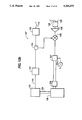
- An embodiment of an optical position sensing system 100 is shown in FIG. 3.
- An RF chirp source 102 produces an RF signal with a linearly varying frequency over a chirp duration T. This RF signal is sometimes referred to as a "chirped" RF signal.
- the chirped RF signal is split into two chirped RF signals using an RF splitter or power divider 104. One of the two chirped RF signals is used to drive (intensity modulate) a light source 106 and the other is used as an RF local oscillator signal which is input to an RF mixer 108.
- Light source 106 outputs an intensity modulated (IM) optical signal with an envelope which is chirped in phase with the chirped RF signal.
- IM intensity modulated
- the chirped IM optical signal is guided down a first transmitting optical fiber 110 to an optical coupler 111 and then to an optical coupler 112 via transmitting/receiving fiber 110' where it is divided, in a known manner, into N chirped IM optical signals, where N is a positive integer.
- These N chirped IM optical signals are input to N second transmitting optical fibers 114 each of which transmits one of the N chirped IM optical signals to one of N position sensor heads 116 (corresponding to sensor heads 4 in FIG. 1).
- RF chirp source 102 can be an electrically controlled rf source such as a YIG tuned oscillator for example as Ferretec FS02106.
- RF chirp source 102 can also be a processor with a digital-to-analog converter that creates digital signals representing RF chirps and then digital-to-analog converts the chirps.
- Light source 106 could be a laser diode such as Lasertron QLM1300MW, a solid state laser, or even a light emitting diode (LED).
- First transmitting fiber 110 and N second transmitting fibers 114 can be multi-mode or single mode fibers.
- An example of RF splitter 104 is Picosecond Labs 5330.
- optical coupler 111 is Australian Optical Fiber AOFR AS50-09-R-C-ST which is a 2 ⁇ 2 asymmetric coupler. If light source 106 is a pigtailed diode laser with fiber 110 being a single mode fiber and pigtailed to light source 106 then coupler 111 can be a multimode coupler and yet optical coupling loses remain low ( ⁇ 3dB) since the single mode pigtail excites only lower order modes in transmitting/receiving fiber 110' and multimode transmitting fibers 114 when light approaches sensor heads 116.
- FIG. 4 shows a closeup view of one of the position sensor heads 116 corresponding to sensor heads 4 in FIG. 1.
- Sensor head 116 is embedded in sensor tube 25.
- One of the N chirped IM optical signals is output by a second transmitting fiber 114 to a lens 118 which collimates the chirped IM optical signal into a collimated beam 120.
- Collimated beam 120 travels to a corner cube 122 which acts as a retroreflector reflecting the collimated beam 120 back through lens 118 and into second transmitting fiber 114.
- Corner cube 122 is secured to an end face 124a of a rod 124 which corresponds, for example, to rod 24 in actuator 20 shown in FIG. 2.
- any type of reflecting surface can be used in lieu of corner cube 122 as long as it scatters sufficient optical energy back to second transmitting fiber 114.
- the end of rod 124 can be coated with a commercially available retroreflective material or the end surface of rod 124 may already be sufficiently reflective to serve the intended purpose.
- beam 120 After scattering off corner cube 122, beam 120 passes back through lens 118 as a chirped IM optical target signal (sometimes referred to herein as a position sensing optical signal) and into second transmitting fiber 114 which guides the chirped IM optical target signal back to optical coupler 112. This occurs for each of N position sensor heads 116 corresponding to N second transmitting fibers 114.
- the N chirped IM optical target signals are then redirected by optical coupler 112 to transmitting/receiving fiber 110' to coupler 111 then to a receiving fiber 126 which guides the N chirped IM optical target signals to a photodiode receiver (or detector) 128.
- Photodiode receiver 128 detects the N chirped IM optical target signals and outputs corresponding N delayed chirped RF target signals.
- Receiving fiber 126 can also be a single or multi-mode fiber.
- An example of photodiode receiver 128 is Antel ARD-28.
- the 110' sensor head 116 delays the i th chirped IM optical signal by an additional amount, ⁇ t i corresponding to the time that beam 120 travels a distance ⁇ L Si . That is, beam 120 travels from tip 115 of second transmitting fiber 114 through lens 118 to corner cube 122 back through lens 118 and to tip 115 in time ⁇ ti. Therefore, the total delay ⁇ T Ti for the i th chirped IM optical signal is
- Photodiode receiver 128 outputs N delayed chirped RF target signals starting at N different times corresponding to N delays ⁇ T T1 , . . . , ⁇ T TN .
- These N delayed chirped RF target signals are amplified by a linear amplifier 130 which outputs N amplified RF target signals to RF mixer 108.
- RF mixer 108 mixes the N amplified RF target signals with the RF local oscillator signal from RF splitter 104.
- An example of linear amplifier 130 is Miteq AFS4-00101000-30-10P-4, and an example of RF mixer 108 is Avantek TFX18075L.
- FIGS. 5a-5c show graphical representations of the RF mixing process.
- FIG. 5a is a graphical representation (not to scale) in frequency versus time of the RF chirped local oscillator signal and the 1 st, . . . , ith, . . . , N th delayed chirped RF target signals at the inputs of RF mixer 108.
- the 1 st, . . . , ith, . . . , N th delayed chirped RF target signals have delays ⁇ T T1 , . . . , ⁇ T Ti , . . . , ⁇ T TN , respectively.
- FIG. 5b is a graph in frequency versus time of the N intermediate frequency (IF) target signals output by RF mixer 108.
- mixing the RF local oscillator signal with the N delayed chirped RF target signals results in N intermediate frequency (IF) target signals with peak frequencies F T1 , . . . , F Ti , . . . , F TN , corresponding to delays ⁇ T T1 , . . . , ⁇ T Ti , . . . , ⁇ T TN , respectively.
- FIG. 5c shows a Fourier transformation of the N intermediate frequency target signals when delays ⁇ T T1 , . . . , ⁇ T TN are adequately spaced apart; namely, when the lengths of N second transmitting fibers 114 are chosen such that the peak frequencies F T1 , F T2 , . . . , F TN are sufficiently spread apart to be filtered later.
- an N channel filter or de-multiplexing filter 132 filters and passes the N IF target signals to nonlinear devices 134 which square the respective N IF target signals and output N squared IF target signals to respective audio low pass filters 136.
- Non-linear devices 134 are advantageous if not only IF target but also IF reference signals are used as will be discussed further below. Therefore, at this point non-linear devices 134 and low pass filters 136 can be bypassed and the N IF target signals can be input directly to analog-to-digital (A/D) converter 136.
- An analog-to-digital (A/D) converter 138 synchronously samples and digitally multiplexes the N IF target signals output by audio low pass filters 136.
- a digital processor 140 then receives the digitized signals from A/D converter 138 and calculates and sends position information to flight controller 8 via a bus 141.
- Digital processor 140 synchronizes data gathering with the generation of RF chirp ramping by RF chirp source 102 by sending RF chirp source 102 clock information via line 143.
- Digital processor 140 can also digitally create chirps and digital-to-analog convert these digital chirps to an analog chirped RF signal for modulating light source 106.
- An example of digital processor 140 is an IBM AT compatible microcomputer with a Mercury MC-32-AT-IO-6 vector processing board.
- the active electronics as described above may be packaged as a unit 142 and placed in an electro-magnetic shield 145 (FIGS. 1 and 3) and thus confined to a single location on helicopter 6.
- Electro-magnetic shield 145 can be made of metal and could shield controller 8 as well.
- the delays ⁇ T T1 , . . . , ⁇ T Ti , . . . , ⁇ T TN vary due to temperature changes of first transmitting fiber 110, transmitting/receiving fiber 110', the N second transmitting fibers 114 and receiving fiber 126. This can lead to significant errors in the position measurement of rod 124.
- temperature sensitivity of the index of refraction for glass is approximately 10 -5 /°C. so that a shift in temperature of 150° C. can lead to a 4.5 cm range measurement error for a 30 meter long fiber.
- vibrations in first transmitting fiber 110, optical coupler 112, N second transmitting fibers 114 or receiving fiber 126 can cause a shift in the peak frequencies F T1 , .
- N chirped IM optical "reference" signals along with the N chirped IM optical target signals as discussed below.
- These N chirped IM optical reference signals experience nearly identical delays from temperature fluctuations and fiber vibrations as the N chirped IM optical target signals.
- the N chirped IM optical reference signals are detected by photodiode receiver 128 which outputs N corresponding chirped RF reference signals which are also mixed with mixer 108 to produce N IF reference signals.
- the N chirped IM optical reference signals are produced, for example, from radiation scattered back off tips 115 (FIG. 4) of N second transmitting fibers 114 due to a fibercore/air interface at tips 115. They can also be produced using connectors or fusion iced in-line references which are relatively close (e.g. ⁇ 1 m) to tips 115 of N second transmitting fibers 114. Hence, the N chirped IM optical signals are scattered back through N second transmitting fibers 114, optical coupler 112 and return fiber 126, and are detected by photodiode receiver 128. The amplitudes of the N chirped IM optical reference signals can be varied depending on how tips 115 are cleaved.
- tips 115 are cleaved at an angle with respect to a 90° transverse cross section of the N second transmitting fibers 114, then the amplitudes of the N chirped IM optical signals can be reduced. Also, if tips 115 are coated with a dielectric such as titanium dioxide (TiO2), the amplitudes of the N chirped IM optical reference signals can be increased. It is desireable to have N target and N reference signals with approximately the same amplitudes.
- TiO2 titanium dioxide
- L Fi length of total fiber to the i th sensor lead 116.
- L Si distance between tip 115 and corner cube 122 for i th sensor head 116.
- Equation 3b can be used to determine the position L Si of rod 124 in each position sensor head 116.
- the position measurement of each rod 124 is independent of mechanical and thermal effects that change the fiber length or propagation velocity of optical radiation in any of the fibers in optical position sensing system 100.
- FIGS. 6a-6c correspond to FIGS. 5a-5c with the additional N chirped optical reference signals.
- FIG. 6a shows the RF local oscillator signal and the 1 st, . . . , ith, . . . , N th delayed chirped RF target and reference signals at the input of RF mixer 108.
- the 1 st, . . . , ith, . . . , N th delayed chirped RF target signals have delays ⁇ T T1 , . . . , ⁇ T Ti , . . . ⁇ T TN , respectively and the 1 st, . . . , ith, . . . , N th delayed chirped RF reference signals have delays ⁇ T R1 , . . . , ⁇ T Ri , . . . ⁇ T RN , respectively.
- FIG. 6b is a graphical representation of the N IF target signals with peak frequencies F T1 , . . . , F Ti , . . . , F TN and the N corresponding IF reference signals with peak frequencies F R1 . . . , F Ri , . . . , F RN , respectively, and chirp duration T.
- the delay of the i th IF target signal is ⁇ T Ti and the delay of the i th reference signal is ⁇ T Ri .
- the delay of the i th target signal ⁇ T Ti is greater than the delay of the i th reference signal ⁇ T Ri . Consequently, the peak frequency F Ti of the i th IF target signal is greater than the peak frequency F Ri of the i th IF reference signal as shown in FIG. 6b.
- FIG. 6b also shows that the i th IF target signal is available to be sampled by A/D converter 138 for a time T Ti and the i th IF reference signal is available to be sampled for a time T Ri , where ##EQU1##
- sensor heads 116 are located 20 to 30 meters from active electronics unit 142 and therefore ⁇ T Ti and ⁇ T Ri are much smaller than T. Consequently the time that A/D converter 138 can sample the target signal and the reference signal is approximately the duration T of the chirp.
- the difference in delay between the delay of the target signal ⁇ T Ti and the delay of the reference signal ⁇ T Ri is ⁇ t i , i.e.,
- the i th delay ⁇ t i is related to the i th target position L Si by ##EQU2##
- FIG. 6c shows a frequency spectrum of the IF target and reference signals at the output of RF mixer 108 when the N chirped RF reference signals are mixed with the local oscillator signal.
- the peak frequencies F R1 , F R2 , . . . , F RN corresponding to each of the N IF reference signals will vary with temperature and vibrations in a manner nearly identical to variations in peak frequencies F T1 , F T2 , . . . , F TN , respectively, of the IF target signals.
- N channel filter 132 in FIG. 3 is made of N bandpass filters with output channels 1, . . . , N coupled into non-linear devices 134.
- Transfer characteristics of non-linear device 134 should be as close to "square law" as possible so as to minimize harmonics of the difference frequencies F Di .
- Examples of non-linear devices 134 include crystal detectors, mixers, RF power detectors or zero-biased diodes, saturated amplifiers, logarithmic amplifiers, analog multipliers and limiters.
- non-linear devices 134 are input to audio low pass filters 136 in order to eliminate the sum terms F Si .
- Analog-to-digital (A/D) converter 138 synchronously samples and digitally multiplexes analog signals output by audio low pass filters 136.
- Digital processor 140 receives the digitized difference signals from A/D converter 138 and determines the N difference frequencies F D1 , . . . , F DN relative to which the positions L Si of rods 124 are directly proportional, independent of temperature variations and vibration as previously explained.
- An alternative approach to obtaining F Di involves bypassing nonlinear devices 134 and directly determining peak frequencies F Ri and F Ti using digital processor 140. Once peak frequencies F Ri and F Ti are determined, difference frequency F Di could be calculated by subtracting F Ri from F Ti using digital processor 140, thereby cancelling out errors due to temperature variations and mechanical vibrations as discussed above. In addition, this approach can cancel out errors caused by the non-repeatability in the slope (frequency versus time) of chirps. However, this approach can result in a performance penalty due to non-linearities in frequency versus time of any one chirp output by chirp source 102 as will now be discussed.
- estimation error ⁇ L Ti (which is defined here to be the accuracy of the estimation) and target signal-to-noise density ratio (SNDR TARi ) at the output of photodiode receiver 128 for the i th IF target signal are given by ##EQU3##
- SHOT NOISE and THERMAL NOISE are receiver parameters
- INTENSITY NOISE is a laser parameter
- B is the RF chirp bandwidth
- T is the estimation time (chirp duration)
- c is the speed of light.
- controller 8 of helicopter 6 typically requires data from sensor heads 4 (or 116 in FIG. 3) to be output at rates exceeding several hundred Hz and lag times under about 0.5 ms. Therefore, the chirp duration T should not exceed about 1 ms.
- actuators such as actuator 20 of FIG. 2, can have stroke lengths L i ranging from 0.5 cm to over 50 cm requiring an accuracy ⁇ L Si of less than 200 micrometers depending on the particular actuator. In order to achieve this accuracy, the chirp bandwidth B should be as large as possible.
- RF chirp source 102 must output a chirp which is linear to within a few kHz. In practice such linearity is not achievable over such a broad bandwidth and at such high chirp rates. However, non-linear devices 134 eliminate errors due to non-linearities of chirp source 102 as will be discussed below.
- FIGS. 7a-7c correspond to FIGS. 6a-6c but with nonlinear frequency versus time variations which occur in RF chirp source 102.
- FIG. 7a shows the RF local oscillator signal and the 1 st, . . . , ith, . . . , and N th delayed non-linear chirped target and reference signals at the input of RF mixer 108.
- the 1 st, . . . , ith, . . . , N th delayed non-linear chirped RF target signals have delays ⁇ T T1 , . . . , ⁇ T Ti , . . . ⁇ T TN , respectively, and the 1 st, . .
- N th delayed nonlinearly chirped RF reference signals have delays ⁇ T R1 , . . . , ⁇ T Ri , . . . ⁇ T RN , respectively.
- FIG. 7b corresponds to FIG. 6b taking into account nonlinearity of the chirped RF signal output by RF chirp source 102. If the total optical path length of the i th second transmitting fiber 114 added to the first transmitting fiber 110, transmitting/receiving fiber 110', and receiving fiber 126 is much larger than the corresponding stroke length L i , then the condition ⁇ t i ⁇ T Ti ⁇ T Ri holds. In this case, non-linearities appearing at the output of mixer 108 nearly identically track each other as shown in FIG. 7b.
- FIG. 7c shows a possible output of one of the channels in N channel filter 132.
- the distortions of the spectrum shown in FIG. 7c can be attributed to non-linear chirps produced by RF chirp source 102. Although the main lobes of the spectra corresponding to IF target and reference signals are identifiable, there is significant distortion around their peaks. These spectral distortions result in significant estimation errors of the peak frequencies F Ri and F Ti . This distortion can be so great that the main lobes can be difficult to distinguish from the side lobes and it may be impossible to resolve the target signal from the reference signal.
- FIG. 8 shows a measured spectrum for a single channel output of audio low pass filters 136 after the N IF target and N IF reference signals pass through non-linear devices 134.
- the spectrum of the difference signal with peak frequency F Di and a DC signal is shown, with the spectrum corresponding to the difference signal being nearly symmetric about its peak frequency.
- the side lobes of the spectrum of the difference signal are about 12 dB down from the main lobe peak.
- the ratio of delays ⁇ t i / ⁇ T Ri increases, the advantage obtained by using non-linear devices 134 decreases, because non-linearities appearing in the reference signals and target signals will not track each other as well.
- RF chirp source 102 need not output extremely linear chirps and yet it is possible to obtain an extremely accurate estimation of peak frequency F Di using digital processor 140.
- FIG. 9a is a block diagram illustrating a functional representation of digital processor 140 which includes a searcher 150 and a tracker 160.
- FIG. 9b shows the bandwidth ⁇ F i corresponding to a full stroke length L i for i th position sensor head 116.
- FIG. 10 shows processing steps for the search mode and the tracking mode of processor 140 using digital processing techniques as are found in Digital Signal Processing by Oppenheim and Schafer, Prentice Hall, Inc., Englewood Cliffs, N.J. (1975), incorporated herein by reference.
- Searcher 150 is activated when processor 140 is in the search mode (steps 200-208) and tracker 160 is activated when processor 140 is in the track mode (steps 220-226).
- Searcher 150 operates as follows.
- digital processor 140 receives the i th digitized difference data on databus 139 from A/D converter 138.
- Searcher 150 then windows and zero pads the i th digitized difference data at step 202 and a fast Fourier transform (FFT) is performed using the i th windowed zero-padded difference data at step 204 according to the processing techniques described in Digital Signal Processing, cited above.
- a Tukey window is used in order to suppress any interfering tones and to reduce bias as a consequence of the i th difference signal being available to be sampled only for a finite duration which is approximately the chirp duration T as discussed above. Tukey windows are also discussed in Digital Signal Processing.
- the FFT data is squared at step 205 and searcher 150 then selects the maximum of the squared FFT data and one point on each side of the maximum point at step 206. Searcher 150 then performs quadratic interpolation at step 208 using the 3 points from step 206 to provide a coarse estimate of the peak difference frequency F Di .
- FIG. 11a shows the plot of amplitude versus frequency after performing the FFT of step 204 and the magnitude squaring of step 205.
- zero-padding by a factor of m increases the resolution from 1/T to 1/mT.
- the asterisks "*" with no circles correspond to i th Fourier transformed difference data absent zero-padding.
- the asterisks with circles together with the asterisks without circles represent the Fourier transformed zero-padded data resulting from step 204.
- the resolution of the spectrum was doubled because the number of zeros added to the difference data was chosen to be N s (the number of sample points).
- Equations 7b and 8b, respectively indicate that the difference frequency F Di can be determined to much higher accuracies (e.g. ⁇ 1 Hz). Therefore, after the magnitude squaring step 205 is performed, quadratic interpolation step 206 is used to obtain a coarse estimate of difference frequency F Di .
- searcher 150 Once searcher 150 has output the coarse estimation of the difference frequency F Di , it goes into the tracking mode as shown in FIG. 10.
- the first time through steps 220-224 (the tracking mode) tracker 160 uses the same set of i th difference data used in the searching mode together with the coarse estimate of difference frequency F Di to determine a fine estimate of difference frequency F Di .
- the coarse estimation of the difference frequency F Di from searcher 150 (step 210) is used together with the initial set of i th digitized difference data obtained at step 220 to calculate three discrete Fourier transform (DFT) points.
- FIG. 11b shows inside circle A of FIG. 11a containing the 3 squared zero-padded windowed FFT difference data.
- Quadratic interpolation step 20 involves calculating the location of the peak of the hypothetical quadratic "a".
- the coarse estimation of the difference frequency F Di is the frequency which corresponds to this location.
- Steps 223 and 224 are similar to steps 205 and 208, respectively, but uses the three points in circle A' (see FIG. 11c) rather than the three points in circle A (see FIG. 11b).
- the coarse estimate of the difference frequency F Di is used to determine which of all J possible frequencies is closest to the coarse estimate of the difference frequency F Di .
- Step 225 includes checking the quality of the estimation of the difference frequency. This can be done by using the value of the amplitude of the quadratic interpolation estimate of F Di . If the amplitude changes by more than a predetermined amount, for example, 10% of the amplitude of the last good estimate of F Di , then the measurement may be invalid. In such a case, the previous estimate of F Di is used in step 222 rather than the current estimate.
- a predetermined amount for example, 10% of the amplitude of the last good estimate of F Di
- Tracker 160 repeats steps 220-225 at rates corresponding to position update rate R' i .
- step 222 of tracker 160 can be performed in a much shorter time than step 204 of searcher 150 because step 204 requires approximately pN s log 2 pN s calculations, whereas step 222 requires approximately 6N S calculations where N s is the number of sample points and p is an integer corresponding to the number of sets of N s zeros which are added to the original Ns sample points.
- This enables digital processor 140 to output frequency F Di with high accuracies ( ⁇ Fi of less than 1 Hz) over a bandwidth ⁇ Fi of 20 kHz corresponding to stroke length Li of 50 cm with lag time T Li less than 0.5 ms.
- Lag time T Li can be reduced to nearly zero by performing dot products on the incoming data as it is being collected.
- FIG. 12a is a schematic diagram of a second embodiment of the invention with an active electronics unit 142' corresponding to active electronics unit 142 in FIG. 3. Like elements in FIGS. 3 and 12a have corresponding reference numerals.
- RF mixer 108 outputs the N IF target signals and N IF reference signals to an N-way RF power splitter 300 which has N RF outputs 301. Each of N RF outputs 301 has all 2N IF signals but at reduced power levels.
- the frequencies fi of each of signal generators 304 i are chosen so that RF mixers 302 output N frequency shifted target IF signals and N frequency shifted reference IF signals with frequencies F Ti and F Ri , respectively.
- Filters 306 i-N receive the N frequency shifted target IF signals and N frequency shifted reference IF signals.
- Each mixing frequency fi output by signal generator 304 i is chosen so that the corresponding i th frequency F Ti of i th frequency shifted target IF signal and frequency F Ri of i th frequency shifted reference IF signal is passed by the i th filter 306.
- N non-linear devices 134 receive and square the filtered N frequency shifted target and N frequency shifted reference IF signals and each non-linear device 134 outputs a sum and difference signal with frequencies F Si and F Di , respectively, for each of N position sensor heads 116.
- audio low pass filters 136 pass only the difference signals with peak frequencies F Di to A/D converter 138, and digital processor 140 searches and tracks successive peak frequencies F Di as discussed above.
- an IQ demodulator 302' or quadrature mixer RR-48 by KDI/Triangle Electronics was used.
- IQ demodulator has two outputs, one corresponds to the signal output by mixers 302 in FIG. 12a and the other corresponds to that same signal shifted in phase by 90 degrees. These signals are filtered by IQ filters 36 and sampled by A/D converter 138.
- FIGS. 13a-13c show a series of actual output data for a fiber optic position sensing system of FIG. 12b.
- the peak frequencies F T1 and F R1 were fairly well defined, it was possible to simply subtract the peak frequency F T1 from the peak frequency F R1 to obtain difference frequency F D1 .
- FIG. 13a shows a series of 130 actually measured peak target frequencies F T1 .
- FIG. 13b shows a corresponding frequency versus time graph of 130 actually measured peak reference frequencies F R1 .
- FIG. 13c shows the resulting difference frequencies F D1 .
- the difference frequency F D1 is F T1 -F R1 , which yields an average difference frequency aveF D1 of 25,746.3 Hz.
- Estimation of the actual difference frequency of the difference signal shown in FIG. 8 was achieved using active electronics unit 142 in FIG. 1, i.e., using non-linear devices 134.
- T 1 ms
- B 6 GHz
- Ri 250 Hz
- T Li 100 microseconds
- an rms position error of 50 micrometers was achieved. Therefore, in addition to cancelling non-repeatability of chirp slope from RF chirp source 102, errors due to non-linearities in each individual chirp were also significantly reduced.
- FIG. 14 shows a plot of bias errors in position measurements by a fiber optic position sensing system employing principles of the invention (including non-linear devices 134) compared to bias errors in position measurements by an electronic sensor.
- the target was moved 100 mm in known increments and its position measured while at rest.
- the RMS error of the fiber optic position sensing system with one sensor head 116 was measured to be 25 micrometers.
- FIG. 15 is a block circuit diagram of an embodiment of active electronics unit 142"' with a digital filter 400 and a digital squaring unit 402.
- Digital filter 400 and digital squaring unit 402 can be implemented using specifically designated hardware or using software with digital processor 140.
- the sampled data from A/D converter 138 are input to filter 400 and filtered and then input to digital squaring unit 402 and squared.
- the difference signal of the squared digital data from digital squaring unit 402 is input to searcher 150 to acquire a coarse estimate of difference frequency F Di and then to tracker 160 for a fine estimate of the difference frequency F Di .
- searcher 150 and tracker 160 operate in the same manner as described above.
Landscapes
- Physics & Mathematics (AREA)
- Electromagnetism (AREA)
- Engineering & Computer Science (AREA)
- General Physics & Mathematics (AREA)
- Computer Networks & Wireless Communication (AREA)
- Radar, Positioning & Navigation (AREA)
- Remote Sensing (AREA)
- Optical Radar Systems And Details Thereof (AREA)
- Length Measuring Devices By Optical Means (AREA)
- Measuring Temperature Or Quantity Of Heat (AREA)
Priority Applications (4)
| Application Number | Priority Date | Filing Date | Title |
|---|---|---|---|
| US07/752,109 US5294075A (en) | 1991-08-28 | 1991-08-28 | High accuracy optical position sensing system |
| PCT/US1992/007278 WO1993005409A1 (fr) | 1991-08-28 | 1992-08-27 | Systeme optique de haute precision de detection de position |
| US08/130,509 US5422477A (en) | 1991-08-28 | 1993-10-01 | High accuracy optical rotation sensing system |
| US08/130,519 US5467942A (en) | 1991-08-28 | 1993-10-01 | Temperature sensing optical system |
Applications Claiming Priority (1)
| Application Number | Priority Date | Filing Date | Title |
|---|---|---|---|
| US07/752,109 US5294075A (en) | 1991-08-28 | 1991-08-28 | High accuracy optical position sensing system |
Related Child Applications (2)
| Application Number | Title | Priority Date | Filing Date |
|---|---|---|---|
| US08/130,519 Continuation-In-Part US5467942A (en) | 1991-08-28 | 1993-10-01 | Temperature sensing optical system |
| US08/130,509 Continuation-In-Part US5422477A (en) | 1991-08-28 | 1993-10-01 | High accuracy optical rotation sensing system |
Publications (1)
| Publication Number | Publication Date |
|---|---|
| US5294075A true US5294075A (en) | 1994-03-15 |
Family
ID=25024915
Family Applications (3)
| Application Number | Title | Priority Date | Filing Date |
|---|---|---|---|
| US07/752,109 Expired - Lifetime US5294075A (en) | 1991-08-28 | 1991-08-28 | High accuracy optical position sensing system |
| US08/130,519 Expired - Lifetime US5467942A (en) | 1991-08-28 | 1993-10-01 | Temperature sensing optical system |
| US08/130,509 Expired - Fee Related US5422477A (en) | 1991-08-28 | 1993-10-01 | High accuracy optical rotation sensing system |
Family Applications After (2)
| Application Number | Title | Priority Date | Filing Date |
|---|---|---|---|
| US08/130,519 Expired - Lifetime US5467942A (en) | 1991-08-28 | 1993-10-01 | Temperature sensing optical system |
| US08/130,509 Expired - Fee Related US5422477A (en) | 1991-08-28 | 1993-10-01 | High accuracy optical rotation sensing system |
Country Status (2)
| Country | Link |
|---|---|
| US (3) | US5294075A (fr) |
| WO (1) | WO1993005409A1 (fr) |
Cited By (23)
| Publication number | Priority date | Publication date | Assignee | Title |
|---|---|---|---|---|
| WO1995021358A1 (fr) * | 1994-02-01 | 1995-08-10 | Yeda Research And Development Co., Ltd. | Centrale solaire |
| WO1996027849A1 (fr) * | 1995-03-03 | 1996-09-12 | Northrop Grumman Corporation | Compensation stable pour mesure de ftm |
| US6282417B1 (en) * | 1998-05-08 | 2001-08-28 | David K. Ward | Communication radio method and apparatus |
| US20060054737A1 (en) * | 2004-09-14 | 2006-03-16 | The Boeing Company | Tandem rotor wing rotational position control system |
| US20060132803A1 (en) * | 2004-12-17 | 2006-06-22 | The Boeing Company | Method and apparatus for combining a targetless optical measurement function and optical projection of information |
| US20060182383A1 (en) * | 2005-02-17 | 2006-08-17 | Anthony Slotwinski | Compact fiber optic geometry for a counter-chirp FMCW coherent laser radar |
| US20060220937A1 (en) * | 2005-04-05 | 2006-10-05 | Harrell Michael E | Swept delta-sigma modulation direct digital synthesis |
| US20120237205A1 (en) * | 2011-03-16 | 2012-09-20 | Baker Hughes Incorporated | System and method to compensate for arbitrary optical fiber lead-ins in an optical frequency domain reflectometry system |
| US20130093598A1 (en) * | 2011-10-12 | 2013-04-18 | Baker Hughes Incorporated | Enhancing functionality of reflectometry based systems using parallel mixing operations |
| US20160231367A1 (en) * | 2014-05-09 | 2016-08-11 | Raytheon Company | Method and system to detect and characterize electromagnetic pulses for the protection of critical infrastructure components |
| US10230459B2 (en) | 2017-02-14 | 2019-03-12 | The Boeing Company | System and method for optical time-domain reflectometry and design data wire testing |
| WO2019070751A1 (fr) * | 2017-10-02 | 2019-04-11 | Bridger Photonics, Inc. | Traitement de segments temporels de fluctuations de longueur d'onde de laser et exemples d'utilisation dans des procédés et appareils de lidar à onde entretenue modulée en fréquence (fmcw) |
| US10436652B2 (en) * | 2016-05-19 | 2019-10-08 | Kidde Technologies, Inc. | Optical health monitoring for aircraft overheat and fire detection systems |
| US10527412B2 (en) | 2015-10-06 | 2020-01-07 | Bridger Photonics, Inc. | Gas-mapping 3D imager measurement techniques and method of data processing |
| US10852120B2 (en) | 2014-10-29 | 2020-12-01 | Bridger Photonics, Inc. | Length metrology apparatus and methods for suppressing phase noise-induced distance measurement errors |
| JP2021006814A (ja) * | 2013-12-19 | 2021-01-21 | ディーエスシージー ソルーションズ,インコーポレイテッド | 単一レーザーlidarシステム |
| JP2021510834A (ja) * | 2018-01-16 | 2021-04-30 | ロベルト・ボッシュ・ゲゼルシャフト・ミト・ベシュレンクテル・ハフツングRobert Bosch Gmbh | 光を送信するための送信装置 |
| US11112308B2 (en) | 2017-11-14 | 2021-09-07 | Bridger Photonics, Inc. | Apparatuses and methods for anomalous gas concentration detection |
| US11422258B2 (en) | 2017-03-16 | 2022-08-23 | Bridger Photonics, Inc. | FMCW LiDAR methods and apparatuses including examples having feedback loops |
| US11422244B2 (en) | 2017-09-25 | 2022-08-23 | Bridger Photonics, Inc. | Digitization systems and techniques and examples of use in FMCW LiDAR methods and apparatuses |
| US11592563B2 (en) | 2017-10-17 | 2023-02-28 | Bridger Photonics, Inc. | Apparatuses and methods for a rotating optical reflector |
| US12066353B2 (en) | 2018-02-01 | 2024-08-20 | Bridger Photonics, Inc. | Apparatuses and methods for gas flux measurements |
| US12153135B2 (en) | 2018-07-18 | 2024-11-26 | Bridger Photonics, Inc. | Methods and apparatuses for range peak pairing and high-accuracy target tracking using FMCW LADAR measurements |
Families Citing this family (24)
| Publication number | Priority date | Publication date | Assignee | Title |
|---|---|---|---|---|
| US5907106A (en) * | 1998-05-22 | 1999-05-25 | Chrysler Corporation | Method and apparatus for measuring strain and load on rotating shafts |
| US6489917B2 (en) * | 2000-11-30 | 2002-12-03 | Georgia Tech Research Corporation | Phase-based sensing system |
| DE10111640A1 (de) * | 2001-03-10 | 2002-10-02 | Airbus Gmbh | Verfahren zur Ermittlung und Meldung von Überhitzungen und Feuern in einem Flugzeug |
| US6912341B2 (en) * | 2002-04-10 | 2005-06-28 | Lockheed Martin Corporation | Optical fiber link |
| US7199764B2 (en) * | 2002-04-10 | 2007-04-03 | Lockheed Martin Corporation | Maintenance platform for a rolling radar array |
| US7183989B2 (en) | 2002-04-10 | 2007-02-27 | Lockheed Martin Corporation | Transportable rolling radar platform and system |
| US6882321B2 (en) * | 2002-04-10 | 2005-04-19 | Lockheed Martin Corporation | Rolling radar array with a track |
| EP1353404A3 (fr) * | 2002-04-10 | 2004-06-30 | Lockheed Martin Corporation | Dispositif radar avec un système d'antennes tournant |
| US6850201B2 (en) * | 2002-04-10 | 2005-02-01 | Lockheed Martin Corporation | Gravity drive for a rolling radar array |
| JP3767544B2 (ja) * | 2002-11-25 | 2006-04-19 | セイコーエプソン株式会社 | 光学装置、照明装置及びプロジェクタ |
| EP1445577A1 (fr) * | 2003-01-30 | 2004-08-11 | ALSTOM Technology Ltd | Procédé et dispositif de détermination de la distance entre une lentille à collimation et un objet |
| US7095493B2 (en) * | 2003-11-24 | 2006-08-22 | The Boeing Company | Optical time domain reflectometer and method of using the same |
| DE10360485B4 (de) * | 2003-12-22 | 2005-11-24 | Airbus Deutschland Gmbh | Verfahren und Vorrichtung zur Temperaturüberwachung entlang einer Messleitung |
| US7127132B1 (en) | 2004-03-08 | 2006-10-24 | Ifos, Inc. | Cascade fiber-optic grating-based sensor apparatus and method |
| US7667830B2 (en) * | 2004-05-13 | 2010-02-23 | The Boeing Company | Mixer-based time domain reflectometer and method |
| JP4580720B2 (ja) * | 2004-09-09 | 2010-11-17 | 株式会社東芝 | リモートセンシング装置 |
| US7639001B2 (en) * | 2006-01-17 | 2009-12-29 | The Boeing Company | Built-in test for high speed electrical networks |
| US8045143B2 (en) * | 2006-10-23 | 2011-10-25 | The Boeing Company | Optical phase domain reflectometer |
| US7821619B2 (en) * | 2008-03-19 | 2010-10-26 | Raytheon Company | Rapid scan LADAR 3D imaging with compact digital beam formation |
| US8270844B2 (en) * | 2009-11-24 | 2012-09-18 | The Regents Of The University Of California | Low jitter RF distribution system |
| US9041594B2 (en) * | 2010-05-24 | 2015-05-26 | Honeywell International Inc. | RF based tracker for rotating objects |
| US8575527B2 (en) * | 2010-11-10 | 2013-11-05 | Lockheed Martin Corporation | Vehicle having side portholes and an array of fixed EO imaging sub-systems utilizing the portholes |
| GB2511809B (en) | 2013-03-14 | 2015-12-23 | Kidde Tech Inc | Thermal event detection and notification system |
| WO2017197306A1 (fr) * | 2016-05-13 | 2017-11-16 | Sri International | Réfractomètre à guide d'ondes à haute performance |
Citations (11)
| Publication number | Priority date | Publication date | Assignee | Title |
|---|---|---|---|---|
| US3900260A (en) * | 1972-07-19 | 1975-08-19 | Mitec Moderne Ind Gmbh | Method and apparatus for measuring the distance and/or relative elevation between two points in an opto-electronic manner |
| US3932745A (en) * | 1974-09-30 | 1976-01-13 | The United States Of America As Represented By The Secretary Of The Army | Far field construction for optical fourier transforms |
| US4011445A (en) * | 1975-12-16 | 1977-03-08 | Hughes Aircraft Company | Optical array active radar imaging technique |
| US4044247A (en) * | 1975-12-16 | 1977-08-23 | Hughes Aircraft Company | Polarization reference imaging technique |
| US4097007A (en) * | 1974-10-15 | 1978-06-27 | The United States Of America As Represented By The Secretary Of The Army | Missile guidance system utilizing polarization |
| US4777661A (en) * | 1986-09-22 | 1988-10-11 | Simmonds Precision Products, Inc. | Apparatus and method for self-referencing and multiplexing intensity modulating fiber optic sensors |
| US4777660A (en) * | 1984-11-06 | 1988-10-11 | Optelecom Incorporated | Retroreflective optical communication system |
| US4824251A (en) * | 1987-09-25 | 1989-04-25 | Digital Signal Corporation | Optical position sensor using coherent detection and polarization preserving optical fiber |
| US4830486A (en) * | 1984-03-16 | 1989-05-16 | Goodwin Frank E | Frequency modulated lasar radar |
| US4848906A (en) * | 1987-02-02 | 1989-07-18 | Litton Systems, Inc. | Multiplexed fiber optic sensor |
| US5031234A (en) * | 1989-05-31 | 1991-07-09 | The United States Of America As Represented By The Administrator Of The National Aeronautics And Space Administration | Fiber optic frequency transfer link |
Family Cites Families (4)
| Publication number | Priority date | Publication date | Assignee | Title |
|---|---|---|---|---|
| US4203326A (en) | 1979-01-26 | 1980-05-20 | Electric Power Research Institute, Inc. | Method and means for improved optical temperature sensor |
| JPS63131006A (ja) * | 1986-11-20 | 1988-06-03 | Yaskawa Electric Mfg Co Ltd | レ−ザ測長装置 |
| US5030824A (en) * | 1990-02-22 | 1991-07-09 | The Boeing Company | Optical position sensor employing encoder delay |
| US5258614A (en) | 1991-05-13 | 1993-11-02 | The Babcock & Wilcox Company | Optical fiber loop temperature sensor |
-
1991
- 1991-08-28 US US07/752,109 patent/US5294075A/en not_active Expired - Lifetime
-
1992
- 1992-08-27 WO PCT/US1992/007278 patent/WO1993005409A1/fr not_active Ceased
-
1993
- 1993-10-01 US US08/130,519 patent/US5467942A/en not_active Expired - Lifetime
- 1993-10-01 US US08/130,509 patent/US5422477A/en not_active Expired - Fee Related
Patent Citations (11)
| Publication number | Priority date | Publication date | Assignee | Title |
|---|---|---|---|---|
| US3900260A (en) * | 1972-07-19 | 1975-08-19 | Mitec Moderne Ind Gmbh | Method and apparatus for measuring the distance and/or relative elevation between two points in an opto-electronic manner |
| US3932745A (en) * | 1974-09-30 | 1976-01-13 | The United States Of America As Represented By The Secretary Of The Army | Far field construction for optical fourier transforms |
| US4097007A (en) * | 1974-10-15 | 1978-06-27 | The United States Of America As Represented By The Secretary Of The Army | Missile guidance system utilizing polarization |
| US4011445A (en) * | 1975-12-16 | 1977-03-08 | Hughes Aircraft Company | Optical array active radar imaging technique |
| US4044247A (en) * | 1975-12-16 | 1977-08-23 | Hughes Aircraft Company | Polarization reference imaging technique |
| US4830486A (en) * | 1984-03-16 | 1989-05-16 | Goodwin Frank E | Frequency modulated lasar radar |
| US4777660A (en) * | 1984-11-06 | 1988-10-11 | Optelecom Incorporated | Retroreflective optical communication system |
| US4777661A (en) * | 1986-09-22 | 1988-10-11 | Simmonds Precision Products, Inc. | Apparatus and method for self-referencing and multiplexing intensity modulating fiber optic sensors |
| US4848906A (en) * | 1987-02-02 | 1989-07-18 | Litton Systems, Inc. | Multiplexed fiber optic sensor |
| US4824251A (en) * | 1987-09-25 | 1989-04-25 | Digital Signal Corporation | Optical position sensor using coherent detection and polarization preserving optical fiber |
| US5031234A (en) * | 1989-05-31 | 1991-07-09 | The United States Of America As Represented By The Administrator Of The National Aeronautics And Space Administration | Fiber optic frequency transfer link |
Non-Patent Citations (16)
| Title |
|---|
| Breck W. Henderson, "Boeing Develops Fiber Optic Components For Future Aircraft," Aviation Week and Space Technology, May 7, 1990, pp. 84-85. |
| Breck W. Henderson, Boeing Develops Fiber Optic Components For Future Aircraft, Aviation Week and Space Technology , May 7, 1990, pp. 84 85. * |
| Gregory L. Abbas et al., "High-Precision Fiber-Optic Position Sensing Using Diode Laser Radar Techniques," SPIE, Laser-Diode Technology and Applications II, vol. 1219, 1990, pp. 468-479. |
| Gregory L. Abbas et al., High Precision Fiber Optic Position Sensing Using Diode Laser Radar Techniques, SPIE, Laser Diode Technology and Applications II , vol. 1219, 1990, pp. 468 479. * |
| K. I. Mallalieu et al., "FMCW Of Optical Source Enevelope Modulation For Passive Multiplexing Of Frequency-Based Fibre-Optic Sensors", Jun. 12, 1986, 2 pages. |
| K. I. Mallalieu et al., FMCW Of Optical Source Enevelope Modulation For Passive Multiplexing Of Frequency Based Fibre Optic Sensors , Jun. 12, 1986, 2 pages. * |
| M. Kunt `traitment numerique des signaux` 1981, Dunod, Montrouge, FR, see section 4.7.8, pp. 173-174. |
| M. Kunt traitment num rique des signaux 1981, Dunod, Montrouge, FR, see section 4.7.8, pp. 173 174. * |
| Michael de La Chapelle et al., "Diode Laser Radar System Analysis and Design For High Precision Ranging," SPIE, Laser Diode Technology and Applications, vol. 1043, 1989, pp. 228-237. |
| Michael de La Chapelle et al., Diode Laser Radar System Analysis and Design For High Precision Ranging, SPIE, Laser Diode Technology and Applications , vol. 1043, 1989, pp. 228 237. * |
| Patent Abstracts of Japan, vol. 12, No. 388 (P 771) Oct. 17, 1988 & SP,A,63 131 006 (Yaskawa Elec. Mfg. Co Ltd Jun. 3, 1988, see abstract). * |
| Patent Abstracts of Japan, vol. 12, No. 388 (P-771) Oct. 17, 1988 & SP,A,63 131 006 (Yaskawa Elec. Mfg. Co Ltd Jun. 3, 1988, see abstract). |
| R. Gallay et al., "Fibre Optic Sensor Multiplexing By FMAMCW," Phys. D. Appl. Phys. 21, 1988, pp. 144-146. |
| R. Gallay et al., Fibre Optic Sensor Multiplexing By FMAMCW, Phys. D. Appl. Phys. 21, 1988, pp. 144 146. * |
| W. B. Spillman, Jr.,. et al., "Performance Of Integrated Source/Detector Combinations For Smart Skins Incoherent Optical Frequency Domain Reflectory (IOFDR) Distributed Fiber Optic Sensors," SPIE, Fiber Optic Smart Structures and Skins, 1988, pp. 106-118. |
| W. B. Spillman, Jr.,. et al., Performance Of Integrated Source/Detector Combinations For Smart Skins Incoherent Optical Frequency Domain Reflectory (IOFDR) Distributed Fiber Optic Sensors, SPIE, Fiber Optic Smart Structures and Skins , 1988, pp. 106 118. * |
Cited By (41)
| Publication number | Priority date | Publication date | Assignee | Title |
|---|---|---|---|---|
| US5578140A (en) * | 1994-02-01 | 1996-11-26 | Yeda Research And Development Co., Ltd. | Solar energy plant |
| WO1995021358A1 (fr) * | 1994-02-01 | 1995-08-10 | Yeda Research And Development Co., Ltd. | Centrale solaire |
| WO1996027849A1 (fr) * | 1995-03-03 | 1996-09-12 | Northrop Grumman Corporation | Compensation stable pour mesure de ftm |
| US5745609A (en) * | 1995-03-03 | 1998-04-28 | Northrop Grumman Corporation | Fixed pattern compensation with adaptive window for MTF testing |
| US6282417B1 (en) * | 1998-05-08 | 2001-08-28 | David K. Ward | Communication radio method and apparatus |
| US20060054737A1 (en) * | 2004-09-14 | 2006-03-16 | The Boeing Company | Tandem rotor wing rotational position control system |
| US7546975B2 (en) * | 2004-09-14 | 2009-06-16 | The Boeing Company | Tandem rotor wing rotational position control system |
| US7701592B2 (en) | 2004-12-17 | 2010-04-20 | The Boeing Company | Method and apparatus for combining a targetless optical measurement function and optical projection of information |
| US20060132803A1 (en) * | 2004-12-17 | 2006-06-22 | The Boeing Company | Method and apparatus for combining a targetless optical measurement function and optical projection of information |
| US20060182383A1 (en) * | 2005-02-17 | 2006-08-17 | Anthony Slotwinski | Compact fiber optic geometry for a counter-chirp FMCW coherent laser radar |
| US7139446B2 (en) | 2005-02-17 | 2006-11-21 | Metris Usa Inc. | Compact fiber optic geometry for a counter-chirp FMCW coherent laser radar |
| US20060220937A1 (en) * | 2005-04-05 | 2006-10-05 | Harrell Michael E | Swept delta-sigma modulation direct digital synthesis |
| US20120237205A1 (en) * | 2011-03-16 | 2012-09-20 | Baker Hughes Incorporated | System and method to compensate for arbitrary optical fiber lead-ins in an optical frequency domain reflectometry system |
| US20130093598A1 (en) * | 2011-10-12 | 2013-04-18 | Baker Hughes Incorporated | Enhancing functionality of reflectometry based systems using parallel mixing operations |
| US9546915B2 (en) * | 2011-10-12 | 2017-01-17 | Baker Hughes Incorporated | Enhancing functionality of reflectometry based systems using parallel mixing operations |
| JP2021006814A (ja) * | 2013-12-19 | 2021-01-21 | ディーエスシージー ソルーションズ,インコーポレイテッド | 単一レーザーlidarシステム |
| US20160231367A1 (en) * | 2014-05-09 | 2016-08-11 | Raytheon Company | Method and system to detect and characterize electromagnetic pulses for the protection of critical infrastructure components |
| US9562938B2 (en) * | 2014-05-09 | 2017-02-07 | Raytheon Company | Method and system to detect and characterize electromagnetic pulses for the protection of critical infrastructure components |
| US10852120B2 (en) | 2014-10-29 | 2020-12-01 | Bridger Photonics, Inc. | Length metrology apparatus and methods for suppressing phase noise-induced distance measurement errors |
| US10527412B2 (en) | 2015-10-06 | 2020-01-07 | Bridger Photonics, Inc. | Gas-mapping 3D imager measurement techniques and method of data processing |
| US11656075B2 (en) | 2015-10-06 | 2023-05-23 | Bridger Photonics, Inc. | High-sensitivity gas-mapping 3D imager and method of operation |
| US12510354B2 (en) | 2015-10-06 | 2025-12-30 | Bridger Photonics, Inc. | Gas-mapping 3D imager measurement techniques and method of data processing |
| US11105621B2 (en) | 2015-10-06 | 2021-08-31 | Bridger Photonics, Inc. | High-sensitivity gas-mapping 3D imager and method of operation |
| US12379210B2 (en) | 2015-10-06 | 2025-08-05 | Bridger Photonics, Inc. | High-sensitivity gas-mapping 3D imager and method of operation |
| US11391567B2 (en) | 2015-10-06 | 2022-07-19 | Bridger Photonics, Inc. | Gas-mapping 3D imager measurement techniques and method of data processing |
| US10436652B2 (en) * | 2016-05-19 | 2019-10-08 | Kidde Technologies, Inc. | Optical health monitoring for aircraft overheat and fire detection systems |
| US10841004B2 (en) | 2017-02-14 | 2020-11-17 | The Boeing Company | System and method for optical time-domain reflectometry and design data wire testing |
| US10230459B2 (en) | 2017-02-14 | 2019-03-12 | The Boeing Company | System and method for optical time-domain reflectometry and design data wire testing |
| US11422258B2 (en) | 2017-03-16 | 2022-08-23 | Bridger Photonics, Inc. | FMCW LiDAR methods and apparatuses including examples having feedback loops |
| US11422244B2 (en) | 2017-09-25 | 2022-08-23 | Bridger Photonics, Inc. | Digitization systems and techniques and examples of use in FMCW LiDAR methods and apparatuses |
| WO2019070751A1 (fr) * | 2017-10-02 | 2019-04-11 | Bridger Photonics, Inc. | Traitement de segments temporels de fluctuations de longueur d'onde de laser et exemples d'utilisation dans des procédés et appareils de lidar à onde entretenue modulée en fréquence (fmcw) |
| US11604280B2 (en) | 2017-10-02 | 2023-03-14 | Bridger Photonics, Inc. | Processing temporal segments of laser chirps and examples of use in FMCW LiDAR methods and apparatuses |
| US11592563B2 (en) | 2017-10-17 | 2023-02-28 | Bridger Photonics, Inc. | Apparatuses and methods for a rotating optical reflector |
| US11921211B2 (en) | 2017-10-17 | 2024-03-05 | Bridger Photonics, Inc. | Apparatuses and methods for a rotating optical reflector |
| US11692900B2 (en) | 2017-11-14 | 2023-07-04 | Bridger Photonics, Inc. | Apparatuses and methods for anomalous gas concentration detection |
| US11112308B2 (en) | 2017-11-14 | 2021-09-07 | Bridger Photonics, Inc. | Apparatuses and methods for anomalous gas concentration detection |
| US12553789B2 (en) | 2017-11-14 | 2026-02-17 | Bridger Photonics, Inc. | Apparatuses and methods for anomalous gas concentration detection |
| US12270951B2 (en) | 2018-01-16 | 2025-04-08 | Robert Bosch Gmbh | Transmitting device for emitting light |
| JP2021510834A (ja) * | 2018-01-16 | 2021-04-30 | ロベルト・ボッシュ・ゲゼルシャフト・ミト・ベシュレンクテル・ハフツングRobert Bosch Gmbh | 光を送信するための送信装置 |
| US12066353B2 (en) | 2018-02-01 | 2024-08-20 | Bridger Photonics, Inc. | Apparatuses and methods for gas flux measurements |
| US12153135B2 (en) | 2018-07-18 | 2024-11-26 | Bridger Photonics, Inc. | Methods and apparatuses for range peak pairing and high-accuracy target tracking using FMCW LADAR measurements |
Also Published As
| Publication number | Publication date |
|---|---|
| US5422477A (en) | 1995-06-06 |
| WO1993005409A1 (fr) | 1993-03-18 |
| US5467942A (en) | 1995-11-21 |
Similar Documents
| Publication | Publication Date | Title |
|---|---|---|
| US5294075A (en) | High accuracy optical position sensing system | |
| US5534992A (en) | Optical measuring apparatus | |
| US10578740B2 (en) | Coherent optical distance measurement apparatus and method | |
| EP2329218B1 (fr) | Géométrie compacte à fibre optique pour un radar laser cohérent de type fmcw à modulations de fréquence opposées | |
| US6469778B2 (en) | Coherent laser radar system and target measurement method | |
| US4397551A (en) | Method and apparatus for optical fiber fault location | |
| US4824251A (en) | Optical position sensor using coherent detection and polarization preserving optical fiber | |
| US6580497B1 (en) | Coherent laser radar apparatus and radar/optical communication system | |
| US5125736A (en) | Optical range finder | |
| EP0347215A2 (fr) | Capteur de proximité | |
| EP3452849B1 (fr) | Système de compensation de bruit de phase, et procédé | |
| EP0596614A2 (fr) | Radar à laser avec stockage du faisceau de référence | |
| CN101128717B (zh) | 用于干涉仪绝对距离测量的相位噪声补偿 | |
| CN115407351A (zh) | 干涉时间光检测和测距系统及确定对象距离的方法与设备 | |
| US5701006A (en) | Method and apparatus for measuring distances using fiber optics | |
| US4662741A (en) | Linear FM chirp laser | |
| CN117169908A (zh) | 一种基于微波光子时频传递的空间激光测距系统 | |
| Abbas et al. | High-precision fiber-optic position sensing using diode laser radar techniques | |
| CA1145927A (fr) | Methode et appareil de localisation de defaillances dans les fibres optiques | |
| US4397548A (en) | Distance measuring system | |
| Kingsley et al. | OFDR diagnostics for fiber/integrated optic systems and high resolution distributed fiber optic sensing | |
| US5019704A (en) | Measuring circuit for detecting measurement signals | |
| JPH1062570A (ja) | 遅延時間測定方法及び遅延時間測定装置 | |
| Fuhr et al. | Self-referencing frequency division multiplexing technique for fiber optic sensors | |
| EP0397636B1 (fr) | Dispositif et procédé pour mesurer avec des capteurs à fibre optique, et un capteur à cet effet |
Legal Events
| Date | Code | Title | Description |
|---|---|---|---|
| AS | Assignment |
Owner name: BOEING COMPANY, THE, Free format text: ASSIGNMENT OF ASSIGNORS INTEREST.;ASSIGNORS:VERTATSCHITSCH, EDWARD J.;ABBAS, GREGORY L.;DE LA CHAPELLE, MICHAEL;AND OTHERS;REEL/FRAME:005948/0166 Effective date: 19911022 |
|
| STCF | Information on status: patent grant |
Free format text: PATENTED CASE |
|
| FEPP | Fee payment procedure |
Free format text: PAYOR NUMBER ASSIGNED (ORIGINAL EVENT CODE: ASPN); ENTITY STATUS OF PATENT OWNER: LARGE ENTITY |
|
| FPAY | Fee payment |
Year of fee payment: 4 |
|
| FPAY | Fee payment |
Year of fee payment: 8 |
|
| FPAY | Fee payment |
Year of fee payment: 12 |