US5357489A - Timepiece provided with driving means formed by a piezo-electric motor - Google Patents
Timepiece provided with driving means formed by a piezo-electric motor Download PDFInfo
- Publication number
- US5357489A US5357489A US08/117,808 US11780893A US5357489A US 5357489 A US5357489 A US 5357489A US 11780893 A US11780893 A US 11780893A US 5357489 A US5357489 A US 5357489A
- Authority
- US
- United States
- Prior art keywords
- timepiece
- rotor
- set forth
- stator
- disc
- Prior art date
- Legal status (The legal status is an assumption and is not a legal conclusion. Google has not performed a legal analysis and makes no representation as to the accuracy of the status listed.)
- Expired - Fee Related
Links
- 230000033001 locomotion Effects 0.000 claims description 20
- 230000002093 peripheral effect Effects 0.000 claims description 11
- 230000005540 biological transmission Effects 0.000 claims description 9
- 238000001514 detection method Methods 0.000 claims description 7
- 239000003989 dielectric material Substances 0.000 claims description 3
- 230000008878 coupling Effects 0.000 claims 2
- 238000010168 coupling process Methods 0.000 claims 2
- 238000005859 coupling reaction Methods 0.000 claims 2
- 238000006073 displacement reaction Methods 0.000 description 15
- 210000003323 beak Anatomy 0.000 description 6
- 239000000919 ceramic Substances 0.000 description 4
- 230000001133 acceleration Effects 0.000 description 3
- 238000004026 adhesive bonding Methods 0.000 description 3
- 230000000694 effects Effects 0.000 description 3
- PXHVJJICTQNCMI-UHFFFAOYSA-N Nickel Chemical compound [Ni] PXHVJJICTQNCMI-UHFFFAOYSA-N 0.000 description 2
- 230000009471 action Effects 0.000 description 2
- 230000005284 excitation Effects 0.000 description 2
- 230000001747 exhibiting effect Effects 0.000 description 2
- 239000000463 material Substances 0.000 description 2
- 229910001256 stainless steel alloy Inorganic materials 0.000 description 2
- 239000004575 stone Substances 0.000 description 2
- 229910001369 Brass Inorganic materials 0.000 description 1
- VYZAMTAEIAYCRO-UHFFFAOYSA-N Chromium Chemical compound [Cr] VYZAMTAEIAYCRO-UHFFFAOYSA-N 0.000 description 1
- NRTOMJZYCJJWKI-UHFFFAOYSA-N Titanium nitride Chemical compound [Ti]#N NRTOMJZYCJJWKI-UHFFFAOYSA-N 0.000 description 1
- QCWXUUIWCKQGHC-UHFFFAOYSA-N Zirconium Chemical compound [Zr] QCWXUUIWCKQGHC-UHFFFAOYSA-N 0.000 description 1
- 229910045601 alloy Inorganic materials 0.000 description 1
- 239000000956 alloy Substances 0.000 description 1
- 239000004411 aluminium Substances 0.000 description 1
- 229910052782 aluminium Inorganic materials 0.000 description 1
- XAGFODPZIPBFFR-UHFFFAOYSA-N aluminium Chemical compound [Al] XAGFODPZIPBFFR-UHFFFAOYSA-N 0.000 description 1
- 238000010009 beating Methods 0.000 description 1
- DMFGNRRURHSENX-UHFFFAOYSA-N beryllium copper Chemical compound [Be].[Cu] DMFGNRRURHSENX-UHFFFAOYSA-N 0.000 description 1
- 239000010951 brass Substances 0.000 description 1
- 229910052804 chromium Inorganic materials 0.000 description 1
- 239000011651 chromium Substances 0.000 description 1
- 239000011248 coating agent Substances 0.000 description 1
- 238000000576 coating method Methods 0.000 description 1
- 239000004020 conductor Substances 0.000 description 1
- 238000010276 construction Methods 0.000 description 1
- 238000010586 diagram Methods 0.000 description 1
- 230000003467 diminishing effect Effects 0.000 description 1
- NKZSPGSOXYXWQA-UHFFFAOYSA-N dioxido(oxo)titanium;lead(2+) Chemical compound [Pb+2].[O-][Ti]([O-])=O NKZSPGSOXYXWQA-UHFFFAOYSA-N 0.000 description 1
- 239000012777 electrically insulating material Substances 0.000 description 1
- 239000011810 insulating material Substances 0.000 description 1
- 230000007246 mechanism Effects 0.000 description 1
- 239000007769 metal material Substances 0.000 description 1
- 229910052759 nickel Inorganic materials 0.000 description 1
- 230000004044 response Effects 0.000 description 1
- 230000000717 retained effect Effects 0.000 description 1
- 229910052709 silver Inorganic materials 0.000 description 1
- 239000004332 silver Substances 0.000 description 1
- 239000007787 solid Substances 0.000 description 1
- 239000010935 stainless steel Substances 0.000 description 1
- 229910001220 stainless steel Inorganic materials 0.000 description 1
- 230000009466 transformation Effects 0.000 description 1
- 230000001131 transforming effect Effects 0.000 description 1
- 239000013598 vector Substances 0.000 description 1
- 229910052726 zirconium Inorganic materials 0.000 description 1
Images


Classifications
-
- G—PHYSICS
- G04—HOROLOGY
- G04C—ELECTROMECHANICAL CLOCKS OR WATCHES
- G04C3/00—Electromechanical clocks or watches independent of other time-pieces and in which the movement is maintained by electric means
- G04C3/08—Electromechanical clocks or watches independent of other time-pieces and in which the movement is maintained by electric means wherein movement is regulated by a mechanical oscillator other than a pendulum or balance, e.g. by a tuning fork, e.g. electrostatically
- G04C3/12—Electromechanical clocks or watches independent of other time-pieces and in which the movement is maintained by electric means wherein movement is regulated by a mechanical oscillator other than a pendulum or balance, e.g. by a tuning fork, e.g. electrostatically driven by piezoelectric means; driven by magneto-strictive means
Definitions
- the present invention concerns a timepiece provided with driving means formed by a piezo-electric motor.
- such invention concerns a timepiece including a date display driven by a piezo-electric motor.
- the date display is formed by a disc, generally toothed on the interior, which moves facing an opening and which is driven over a 24 hour period by a reducing gear wheel train, itself operated via the dial train by an electromagnetic motor of the stepping motor type having a bipolar magnet.
- Such wheel train generally includes at least one specific driving wheel which is provided, on the one hand, with standard outer teeth receiving a motor couple from said dial train and which, on the other hand, is provided with an elastic arm which engages with the date disc.
- Such arm is adapted so as to be able to absorb rapid displacements forward or backward from the date disc during rapid correction effected by the user through the time setting crown.
- Such arrangement requires having available other driving means formed by a special correction mechanism including, for example, a sliding pinion cooperating with an intermediate wheel capable of bringing about the rapid correction mentioned hereinabove with the help of the crown.
- the wheel train of the first driving means creates a substantial resistive load on the dial train, even though the date disc need be displaced in normal operation only once every twenty-four hours.
- the data disc must be perfectly positioned relative to the opening following each displacement so that the disc generally cooperates with a jumper spring which increases in a significant manner the resistive couple.
- the present invention has as purpose to overcome these drawbacks in furnishing a timepiece including display means such as a date display operated by driving means permitting the simplification of the overall conception of such timepiece by diminishing the number of its components, its dimensions and the applied load.
- An object of the present invention is to provide a timepiece comprising
- the timepiece being characterized in that said driving means include a piezo-electric motor engaging directly with said display means.
- such piezo-electric motor which comprises a stator and a rotor, includes angular indexing means integrated with said rotor and adapted to stop the rotational movement of the rotor in at least one predetermined angular position.
- said indexing means include a rigid hub which exhibits a cam profile on which an elastic contact blade is brought to rest laterally.
- said blade cooperates with an electric position detection circuit which it opens at a predetermined angular position of the rotor.
- said blade is mounted on a support driven into a base plate or a bridge with interposition of an electric insulator.
- FIG. 1 is a schematic view from above of a timepiece according to the invention showing basically a date disc coupled to driving means according to the invention;
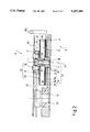
- FIG. 2 is a cross-section taken along line II--II of FIG. 1;
- FIG. 3 is a top view of the driving means of FIG. 2, shown without the date disc;
- FIG. 4 is a view taken along arrow IV of FIG. 5 showing solely a body and transmission blades of a rotor equipping the driving means according to the invention shown on FIGS. 1 to 3;
- FIG. 5 is a view taken according to arrow V of FIG. 4 and showing from the side and in a rest position the assembly body - blades of FIG. 4;
- FIG. 6 is a cross-section view showing driving means according to a second embodiment of the invention.
- FIG. 7 is a side view solely of the rotor and of a stator of the driving means, in particular of FIG. 2, but shown to a different scale for better understanding of the drawings;
- FIG. 8 is a half-view in cross-section of the stator of FIGS. 1 to 3 and 6 and 7 shown in full outline in its rest position and in broken mixed strokes in its two deformed end positions when such stator is excited in vibration according to a first mode of vibratory motion of the driving means according to the invention;
- FIGS. 9 and 10 are diagrams showing the amplitude variation curves of the stator deformation in its first vibration mode as a function respectively of the radius on the stator and of an angular position on the latter;
- FIG. 11 is a half-view in cross-section similar to FIG. 8, but showing a second mode of vibratory motion of the driving means according to the invention.
- FIGS. 12 an 3 are respectively views similar to those of FIGS. 9 and 10, but showing amplitude variation curves of the stator when it is set into vibration according to the vibratory mode of FIG. 11.
- Timepiece 1 which is shown on such figure in a very schematic manner, includes display means, here constituted by a date display 2.
- Timepiece 1 can include other known means of display, not shown, such as an hours and minutes display, a seconds display and a day display which can possibly be associated with still other display means for time or other information without any particular limit.
- the date display disc 4 includes interior teeth 5 made up of teeth 7 (a single one being referenced) spaced apart from one another by oblong slots 9 having parallel sides.
- Timepiece 1 further includes driving means 12 which cooperate directly with the display means 2 and more specifically with the interior teeth 5 and which operate on them in order to assure their displacement in rotation.
- the driving means 12 which are arranged basically under disc 4 include a piezo-electric motor shown more specifically according to a first embodiment on FIGS. 2 to 5.
- Such motor which is identified by the general reference M1 is hung on a support (FIG. 2) which is, in this example, constituted by a footing 3 formed by a base plate of the timepiece 1, partially shown.
- Motor M1 includes a rotor R1 mounted for rotation about a geometric axis X1 on a stator S1 which in its case is fixedly assembled by force fitting (driving) or by gluing in support .
- stator S1 which is thus embedded in footing 3 forms a bearing structure assuring axial support and centering in rotation for rotor R1.
- piezo-electric means 16 On one face F1 of stator S1 arranged facing the footing 3 are mounted piezo-electric means 16 constituted, on the one hand, of a piezo-electric element 16a such as a ceramic uniformly polarized over its thickness and, on the other hand, two electrodes 16b and 16c which are coupled in a known manner to an electric source AL here shown in schematic fashion.
- a piezo-electric element 16a such as a ceramic uniformly polarized over its thickness
- two electrodes 16b and 16c which are coupled in a known manner to an electric source AL here shown in schematic fashion.
- the piezo-electric means 16 form a transducer which, in response to an electric excitation furnished by the source AL via electrodes 16b and 16c, can assume a vibratory motion.
- Such piezo-electric phenomena as well as the construction and arrangement of such piezo-electric transducers in motors of this type are well known to the person skilled in the art and thus will not be described here in a detailed manner.
- Plate P1 is formed on the one hand from a thin elastically deformable disc I 4 under which are mounted, in particular by gluing, the piezo-electric means 16.
- disc 14 exhibits a thin uniform thickness on the order of 0.1 mm (0.1 ⁇ 10 -3 meter).
- the plate P1 on the other hand includes a tubular cylindrical pipe 18 projecting from the disc 14 and materially integral with the latter. Pipe 18 is thus fixedly driven by force mounting or by gluing in an orifice (not referenced) of footing 3.
- the pipe 18 includes a central open orifice 20 in which is driven a headed smooth cylindrical stud V which axially retains and assures centering in rotation of rotor R1, about axis X1, thanks to two coaxial journals (not referenced) arranged on such stud.
- rotor R1 which rests elastically in axial support on face F2 of disc 14 opposite to the face F1 includes a staged tubular hub 22 of rigid structure mounted to rotate about axis X1 directly on stud V.
- Hub 22 includes mechanical engagement means formed by two pins 24 driven into hub 22 and projecting axially therefrom on either side of stud V.
- the two pins 24 are placed on a radial axis X2 of hub 22 passing through the longitudinal axis X1.
- Hub 22 furthermore includes thereunder (according to the orientation of motor M1 in its position shown on FIG. 2) a shouldered journal 26 on which is fixedly engaged the body of rotor R1, in particular by driving.
- the body of rotor R1 is, according to the invention, basically constituted by a flexible perforated disc D1.
- disc D1 includes an annular central portion 28 which includes a central opening 30 intended to be brought to engage on journal 26.
- Disc D1 otherwise includes a peripheral ring 32 on which are formed motion transmission means adapted to transmit to rotor R1 the vibratory motion of stator S1 and to displace rotor R1 in rotation about its axis X1 in an intermediate displacement plane Pdm (FIG. 7), normal to such axis.
- Such transmission means are formed by elastically deformable elements constituted by flexible blades 34 arranged edgewise on disc D1.
- the flexion blades 34 are arranged at the periphery of disc D1 by a cold forming operation and in particular by swaging of the peripheral ring 32.
- disc D1 includes flexible arms 36 (for example here four in number, a single one being referenced) which couple elastically the central portion 28 and the peripheral ring 32.
- the transmission means formed by the flexible blades 34 extending from the peripheral ring 32 towards stator S1, as well as the flexion arms 36, the central portion 28 and ring 32 are materially integral and form a monolithic rotor piece. It will be specified that the peripheral ring 32, the flexible arms 36 and the central portion 28 exhibit the same thickness and are, in the rest state (FIGS. 4 and 5), arranged in a common plane (not referenced).
- the body of rotor R1 is formed by a structure which is elastically deformable, at least in the direction of the stator S1 and which forms, at least partially, elastic support means for rotor R1 on stator S1.
- Such means are formed as well in part by the hub 22 which urges disc D1 axially towards the stator in an axisymmetric fashion (relative to axis X1) in being retained by the head, not referenced, of the embedded stud V.
- the body of rotor R1 is basically formed by the elastically deformable disc D1 which forms in an integrated fashion said transmission means 34 and said elastic support means, not referenced.
- hub 22 deforms permanently the body of rotor R1 which is pre-stressed and which assumes a basin form under the action of stud V.
- Such placing under stress gives rise to axial bearing and counter-bearing forces on the face F2 of stator S1 and at the free end of blades 34.
- electrodes 16b and 16c of the piezo-electric means 16 both exhibit in frontal projection a full solid structure, that is to say, not cut out and not structured by polarized segments as is the case in known structures.
- the disc 14 forming stator S1 is preferably obtained from a metallic material such as brass, a stainless steel alloy or aluminium, possibly coated by a thin layer of a hard material, in particular chromium or titanium nitride. Electrodes 16b and 16c are preferably formed from nickel or silver.
- the flexion blades 34 project from rotor R1 and in particular from disc D1 in the direction of the front face F2 of stator S1 according to an angle of inclination ⁇ having as origin a line parallel to the rotation axis X1; such angle ⁇ being comprised between 10° and 30°.
- each flexible blade 34 which has a planar form of the parallelepipedon type, projects from rotor R1 over a free length Lcs preferably chosen among values situated between 0.1 and 0.5 mm (0.1 and 0.5 10 -3 meter).
- each blade 34 exhibits a thickness ec situated between 0.025 and 0.1 mm (0.025 and 0.1 ⁇ 10 -3 meter) and a width 1c situated between 0.1 and 0.3 mm (0.1 and 0.3 ⁇ 10 -3 meter).
- flexion blades 34 which in being interposed between rotor R1 and stator S1 form a mechanical interface between the latter, end up and rest directly on the front, basically planar, face F2 of stator S1, such face F2 being smooth and free of any projecting element or protuberance.
- the flexible blades 34 and thus disc D1 are formed from a material such as an alloy of the beryllium-copper type or stainless steel type.
- stator S1 exhibits a flexible deformation on either side of its rest position identified by reference A. Such deformation is shown in a greatly exaggerated fashion by the respective high B and low C end positions. In reality, such deformation does not exceed a beating amplitude greater than 5 ⁇ m (5 10 -6 meter), at the periphery of the stator (peak). Such deformation also gives stator S1 a basin form. Such deformation into basin form is due to the flexion stresses generated in stator S1 thanks to the piezo-electric means 16. Such flexible stresses are due to the heterogeneous bimorph structure formed by the rigid assembly of the piezo-electric means 16 on stator S1.
- stator S1 in order to obtain the sought-after deformation of stator S1, there is employed a special ceramic adapted to be radially deformed when a specific electric excitation via the electrodes is applied thereto. More specifically, there has been chosen a ceramic exhibiting a high piezo-electric constant d 31 , such constant representing the deformation obtained relative to the applied field.
- Such vibratory motion is of the axisymmetric type and furnishes to the stator a deformation of the same type. This is corroborated by the curves C1 and C2 of FIG. 9, where it is noted that the amplitude variation Amp of the stator deformation S1 as a function of its radius Rb is of the same sign, that is to say increasing, from the center towards the periphery of the stator S1.
- curves C1 and C2 show no point of inflexion nor any passage through a null amplitude value. Such vibratory mode thus will cause no nodal circle to appear on stator S1.
- curves C3 to Cn show all the amplitude values different from 0 (zero).
- curves C3 to Cn show the variations in amplitude of deformation of the stator as a function of the angular position on the latter for different given values of the radius, such variations being measured for a positive amplitude variation corresponding to curve C1 of FIG. 9.
- curves are straight lines and entirely parallel among themselves, which demonstrates that such vibratory mode does not induce any nodal diameter.
- each point, for example Pt1 to Pt3 (FIG. 7) of stator S1 effects a displacement basically parallel to the rotation axis X1 of the same amplitude on a circle inscribed on the rotor at the level of a given radius (for example Rbl to Rbn) and in phase.
- the vibration mode of the piezo-electric motor according to the invention being axisymmetric, the velocity vectors T at every point of the stator and in particular in the region of contact between the stator and the rotor (three only, T1 to T3 being shown on FIG. 7) are basically normal to the displacement plane Pdm of rotor R1.
- Stator S1 thus exhibits no significant velocity component in the displacement plane Pdm in view of the extremely small vibration amplitudes. It thus exhibits no acceleration of the radial, centrifugal or centripetal type which could be significant. It is also noteworthy that such stator does not show any tangential acceleration which acceleration to the contrary is found in the stators of known piezoelectric motors having an advancing or standing wave vibratory mode.
- FIG. 11 shows the deformation of stator S1 when it is subjected to a second mode of axisymmetric vibratory motion according to the invention, reference D showing its rest position, while references E and F show the behaviour of the stator in its deformed end positions when it is excited.
- Such motion this time exhibits a nodal circle, in particular indicated at radius Rb3 (FIGS. 12 and 13). It is noted in effect that curves C1 and C2 of FIG. 12 pass through a null amplitude value marking a vibratory node in the stator. Curves C3 to Cn of FIG.
- FIG. 13 illustrate the axisymmetric character of the vibratory mode and the deformation of stator S1 in showing that for a given radius Rbx of the stator every circle inscribed on the latter exhibits over an angle of 360° a constant amplitude (peak value), curves C3 to Cn of FIG. 13 being straight lines parallel to one another.
- Such curves C3 to Cn represent the amplitude variations of the stator as a function of the angular positions thereon, such variations being measured for a variation of amplitude corresponding to curve C2 of FIG. 12.
- Such vibratory mode does not induce any nodal diameter on stator S1.
- Such vibratory mode is thus of the type B 10 .
- Hb is the overall height of the suspended portion of the stator (disc 14 plus piezo-electric means 16)
- hb is the height of disc 14, that is to say, the height of the stator without the piezo-electric means 16
- Rb is the maximum radius of the stator (taken at the periphery of disc 14)
- ra is the minor radius of the ring forming the piezo-electric means 16
- ha is the overall height of the piezo-electric means 16 (the thickness of the electrodes here being negligible)
- 1a is the width of the piezo-electric means 16
- F is the vibration frequency of stator S1.
- Disc 14 is in this case constituted by a stainless steel alloy while the piezo-electric element 16a is constituted by a piezo-electric ceramic of the type PZT (lead titanate doped with zirconium).
- PZT lead titanate doped with zirconium
- the piezo-electric means 16 are excited by the electrical source AL, which causes them to vibrate.
- the radial component of the vibration of the piezo-electric means 16 generates a flexure vibration of disc 60 by the heterogeneous bimorph principle known to persons skilled in the art.
- the electrical source AL furnishes an alternating signal of frequency F corresponding to the resonance frequency of the desired mode B XO .
- Stator S1 in its entirety is thus excited in resonance in the mode B XO corresponding to an axisymmetric vibratory motion such as has been described hereinbefore.
- the elastically deformable elements formed by the flexible blades 34 thus form motion transformation means capable of transmitting and at the same time transforming the basically axial linear (or normal) motion of the stator into a perpendicular rotary motion of the rotor.
- indexing means or angular positioning means adapted to stop the rotational motion of rotor R1 in at least one predetermined angular position.
- the means which are here described permit stopping motor M1 in two angular positions separated from one another by 180°.
- Such indexing means include an elastic contact blade 50 which is arranged in the rotation plane (not referenced) of hub 22 and which is formed to come into lateral contact with the outer circumference of the latter at least during a portion of its rotation.
- the elastic contact blade 50 is assembled fixed to the base plate or footing 4 through a support 52 which is driven into the base plate 4 with interposition of a sleeve 54 formed of an electrically insulating material.
- the circumference of hub 22 exhibits a cam profile 56 including two characteristic regions 56a and 56b.
- the two regions 56a and 56b exhibit a generally circular arc form and the curves which form them are off-centered relative to one another and respectively relative to axis X1.
- the two regions 56a and 56b which are discontinuous are reunited in an interrupted fashion through two disjunctions respectively 58a and 58b. At the end of the two regions 56a and 56b are thus formed respective beaks 60a and 60b.
- rotor R1 conforming to the principle described hereinbefore, turns in accordance with the rotation sense shown by arrow RO, of the same sign as the rotation sense (not shown) of the date disc 4.
- motor M1 and the date disc 4 turn in the clockwise sense.
- the beaks 60a and 60b are arranged in the trailing portion of region 56a and 56b.
- disengagements 62a and 62b of oblong form open towards the exterior and oriented in a manner parallel between themselves and both in a manner parallel to the radial axis X2 of the hub 22 on which are aligned the two engagement pins 24.
- each region 56a, 56b shows a variable profile the radius of curvature R of which varies progressively from R1 to R2.
- the leading portions 57a, 57b of the respective regions 56a and 56b are arranged relative to axis X1 on a radius R1 smaller than radius R2 of the corresponding beaks 60a and 60b.
- the free end of the elastic blade 50 is located in one of the disengagements 62a, 62b and is arranged at a distance from the outer circumference of hub 22.
- the source AL furnishes an energization current to stator S1
- the leading portion 57a or 57b arranged facing blade 50 comes into tangential contact with blade 50 which bends initially only slightly.
- the angular displacement of hub 22 in the rotation sense RO increases the stress applied to blade 50 to arrive at a maximum stress at the level of beak 60a or 60b. In this fashion, the stress applied to blade 50 is progressively increased and there is applied at the start a relatively small load on the motor.
- the elastic contact blade 50 is formed of an electrically conductive material or includes a coating or track (not shown) exhibiting such property.
- the timepiece according to the invention includes an electronic control arrangement Dc which is coupled to a watch circuit Ch (here shown in schematic fashion).
- the arrangement Dc is adapted to be able to control the rotation of motor M1 via electric source AL.
- Blade 50 is coupled by a first branch of circuit 64 to the electronic control arrangement Dc which is otherwise connected, according to a first embodiment, to a second circuit branch 66, itself coupled for example to base plate 4.
- both circuit branches 64 and 66, blade 50, motor M1 and the base plate 4 form an electric position detecting circuit 68.
- blade 50 and hub 22 constitute within the detection circuit 68 an electromechanical switch.
- base plate 4 is provided with a conductive stud 70, for example driven thereinto. Stud 70 which is arranged close to blade 50, is coupled to the control arrangement Dc through a circuit branch 72 (shown in interrupted dashes).
- hub 22, the motor assembly M1 and/or base plate 4 or parts thereof can be formed of insulating material such as plastic.
- the detection circuit 68 is open in the rest position of the blade shown on FIG. 3, in which position blade 50 in its electrode function is free from all electric contact with the corresponding electrode formed either by rotor R1 itself (hub 22) or by stud 70.
- circuit Ch furnishes arrangement Dc, in particular close to midnight, time information in the form of a digital signal called the date signal.
- the control arrangement Dc then delivers a control signal to the source A1 which energizes electrically the piezo-electric means 16a to cause stator S1 to vibrate as previously described and to drive rotor R1 in rotation.
- Such displacement in rotation of rotor R1 in the rotation sense RO provokes the subsequent displacement of the date disc 4 via the engaging pins 24 meshing with teeth 5.
- control arrangement Dc which instantaneously cuts energization of the motor in acting on the source AL.
- the operation is substantially identical for the second embodiment, except that the detection circuit 68, which in the rest state, is normally closed when blade 50, under the action of the cam profile 56 of hub 22, comes into lateral contact with stud 70 is found open when blade 50 leaves such contact at the moment in which it falls into one of the disjunctions 58a or 58b.
- Motor M2 includes a stator S2 which is provided with the piezo-electric element 16 and the annular disc 14 described hereinbefore. On such stator S2 is assembled a rotor R2 the body of which is identical to rotor R1 including a flexible perforated disc D2 of the same structure as disc D1.
- Rotor R2 is different in that it includes a staged hub 80 driven onto a driving spindle 82 traversing stator S2 through a pipe 84 materially integral with disc 14 of the suspended plate P2.
- Hub 80 serves only to support the flexible perforated disc D2 in order to maintain it urged as shown on FIG. 6 under elastic stress towards plate P2 of stator S2.
- the driving spindle 82 is assembled by a first guide-means 86 formed by a pivot (same reference) mounted for rotation in a bearing 88 formed, in this example, by a stone driven into a second support 89 formed by a base plate or by a bridge of the timepiece 1 (here shown partially).
- Such spindle 82 is supported in rotation by a second guide means 90 constituted by a cylindrical journal (same reference) arranged on spindle 82 and mounted for rotation in a bearing 92 likewise formed by a stone which is driven into a cavity (not referenced) provided in pipe 84. It will be noted that pipe 84 itself is driven into a base plate or a bridge 94 which forms the support of stator S2.
- the driving spindle 82 which is fixed in rotation to the body of rotor R2 via hub 80 in order to assure its centering around axis X1 is assembled for rotation at least within support 94 which it traverses in order to project outwardly therefrom and to cooperate with the mechanical engaging pins 24.
- Stator S2 shows by way of example the same vibration modes as those previously described, motors M1 and M2 showing by way of example the same dimensions.
Landscapes
- Physics & Mathematics (AREA)
- General Physics & Mathematics (AREA)
- General Electrical Machinery Utilizing Piezoelectricity, Electrostriction Or Magnetostriction (AREA)
Applications Claiming Priority (2)
| Application Number | Priority Date | Filing Date | Title |
|---|---|---|---|
| CH284592A CH685660B5 (fr) | 1992-09-09 | 1992-09-09 | Piece d'horlogerie pourvue de moyens d'entraînement formes par un moteur piezo-electrique. |
| CH2845/92-8 | 1992-09-09 |
Publications (1)
| Publication Number | Publication Date |
|---|---|
| US5357489A true US5357489A (en) | 1994-10-18 |
Family
ID=4242883
Family Applications (1)
| Application Number | Title | Priority Date | Filing Date |
|---|---|---|---|
| US08/117,808 Expired - Fee Related US5357489A (en) | 1992-09-09 | 1993-09-08 | Timepiece provided with driving means formed by a piezo-electric motor |
Country Status (6)
| Country | Link |
|---|---|
| US (1) | US5357489A (fr) |
| EP (1) | EP0587031B1 (fr) |
| JP (1) | JPH06194463A (fr) |
| CN (1) | CN1042978C (fr) |
| CH (1) | CH685660B5 (fr) |
| DE (1) | DE69310643T2 (fr) |
Cited By (11)
| Publication number | Priority date | Publication date | Assignee | Title |
|---|---|---|---|---|
| US5473215A (en) * | 1993-09-08 | 1995-12-05 | Asulab S.A. | Position detector of the rotor of a piezo-electric motor |
| US5726518A (en) * | 1992-07-22 | 1998-03-10 | Nikon Corporation | Supporting device of relative moving element of vibration actuator or vibration motor |
| EP0874292A3 (fr) * | 1997-04-25 | 1999-03-03 | Seiko Instruments Inc. | Pièce d'horlogerie électronique |
| US6088302A (en) * | 1997-04-25 | 2000-07-11 | Seiko Instruments Inc. | Electronic timepiece |
| EP0874293A3 (fr) * | 1997-04-25 | 2001-01-03 | Seiko Instruments Inc. | Pièce d'horlogerie électronique à calendrier |
| US6515941B1 (en) * | 1999-03-02 | 2003-02-04 | Seiko Instruments Inc. | Electronic watch |
| US20040156274A1 (en) * | 1998-03-15 | 2004-08-12 | Osamu Miyazawa | Piezoelectric actuator, timepiece, and portable device |
| US20040233793A1 (en) * | 2002-08-30 | 2004-11-25 | Akihiro Sawada | Analog electronic timepiece |
| US20070145859A1 (en) * | 2005-09-16 | 2007-06-28 | Pentax Corporation | Ultrasonic motor |
| US20120082009A1 (en) * | 2010-10-01 | 2012-04-05 | Rolex S.A. | Timepiece |
| US20170205769A1 (en) * | 2016-01-18 | 2017-07-20 | Eta Sa Manufacture Horlogere Suisse | Timepiece movement including an analogue display |
Families Citing this family (8)
| Publication number | Priority date | Publication date | Assignee | Title |
|---|---|---|---|---|
| FR2741488B1 (fr) | 1995-11-16 | 1998-01-09 | Asulab Sa | Procede et circuit d'excitation et de controle d'un moteur piezo-electrique en mode pas a pas |
| DE10325793A1 (de) * | 2003-06-05 | 2004-12-30 | Borg Instruments Ag | Linearzeiger |
| EP3474085B1 (fr) * | 2017-10-23 | 2020-03-25 | ETA SA Manufacture Horlogère Suisse | Dispositif de commande muni d'un module de détection de la position axiale de sa tige, et pièce d'horlogerie comprenant un tel dispositif de commande |
| EP4198648A1 (fr) | 2021-12-20 | 2023-06-21 | The Swatch Group Research and Development Ltd | Moteur piézoélectrique rotatif, notamment pour l'horlogerie |
| EP4391349B1 (fr) | 2022-12-23 | 2025-10-01 | The Swatch Group Research and Development Ltd | Moteur piézoélectrique rotatif résistant aux chocs, notamment pour l'horlogerie |
| EP4391348B1 (fr) | 2022-12-23 | 2025-10-29 | The Swatch Group Research and Development Ltd | Résonateur piézoélectrique à double pivot rcc, notamment pour moteur rotatif d'horlogerie |
| EP4390557A1 (fr) | 2022-12-23 | 2024-06-26 | The Swatch Group Research and Development Ltd | Resonateur piezoelectrique a spiral, notamment pour moteur rotatif d'horlogerie |
| EP4391347A1 (fr) | 2022-12-23 | 2024-06-26 | The Swatch Group Research and Development Ltd | Résonateur piézoélectrique a guidage flexible, notamment pour moteur rotatif d'horlogerie |
Citations (6)
| Publication number | Priority date | Publication date | Assignee | Title |
|---|---|---|---|---|
| FR2059743A1 (fr) * | 1969-08-29 | 1971-06-04 | Siemens Ag | |
| US3726080A (en) * | 1970-01-16 | 1973-04-10 | Mueller & Co Ag | Control apparatus for an electric timepiece |
| US4786836A (en) * | 1984-03-01 | 1988-11-22 | Matsushita Electric Industrail Co., Ltd. | Piezoelectric motor |
| EP0424140A2 (fr) * | 1989-10-20 | 1991-04-24 | Seiko Epson Corporation | Pièce d'horlogerie électronique |
| US5023853A (en) * | 1988-06-27 | 1991-06-11 | Masayuki Kawata | Electric apparatus with silent alarm |
| US5043956A (en) * | 1989-06-26 | 1991-08-27 | Seiko Instruments Inc. | Wristwatch with oscillation alarm |
Family Cites Families (3)
| Publication number | Priority date | Publication date | Assignee | Title |
|---|---|---|---|---|
| JPS60111178A (ja) * | 1983-11-21 | 1985-06-17 | Seiko Epson Corp | 指針表示式電子時計 |
| JPS62133379A (ja) * | 1985-12-05 | 1987-06-16 | Seiko Epson Corp | 電子時計 |
| JPS6396591A (ja) * | 1986-10-13 | 1988-04-27 | Seiko Epson Corp | 電子時計 |
-
1992
- 1992-09-09 CH CH284592A patent/CH685660B5/fr not_active IP Right Cessation
-
1993
- 1993-09-01 DE DE69310643T patent/DE69310643T2/de not_active Expired - Fee Related
- 1993-09-01 EP EP93113954A patent/EP0587031B1/fr not_active Expired - Lifetime
- 1993-09-07 JP JP5246238A patent/JPH06194463A/ja active Pending
- 1993-09-08 US US08/117,808 patent/US5357489A/en not_active Expired - Fee Related
- 1993-09-08 CN CN93117379A patent/CN1042978C/zh not_active Expired - Fee Related
Patent Citations (6)
| Publication number | Priority date | Publication date | Assignee | Title |
|---|---|---|---|---|
| FR2059743A1 (fr) * | 1969-08-29 | 1971-06-04 | Siemens Ag | |
| US3726080A (en) * | 1970-01-16 | 1973-04-10 | Mueller & Co Ag | Control apparatus for an electric timepiece |
| US4786836A (en) * | 1984-03-01 | 1988-11-22 | Matsushita Electric Industrail Co., Ltd. | Piezoelectric motor |
| US5023853A (en) * | 1988-06-27 | 1991-06-11 | Masayuki Kawata | Electric apparatus with silent alarm |
| US5043956A (en) * | 1989-06-26 | 1991-08-27 | Seiko Instruments Inc. | Wristwatch with oscillation alarm |
| EP0424140A2 (fr) * | 1989-10-20 | 1991-04-24 | Seiko Epson Corporation | Pièce d'horlogerie électronique |
Non-Patent Citations (6)
| Title |
|---|
| Patent Abstracts of Japan; vol. 11, No. 354 (P 638) 19 Nov. 1987 and JP A 62 133 379 (Seiko Epson Corp.) 16 Jun. 1987. * |
| Patent Abstracts of Japan; vol. 11, No. 354 (P-638) 19 Nov. 1987 and JP-A-62 133 379 (Seiko Epson Corp.) 16 Jun. 1987. |
| Patent Abstracts of Japan; vol. 12, No. 334 (P 756) 8 Sep. 1988 and JP A 63 096 591 (Seiko Epson Corp.) 27 Apr. 1988. * |
| Patent Abstracts of Japan; vol. 12, No. 334 (P-756) 8 Sep. 1988 and JP-A-63 096 591 (Seiko Epson Corp.) 27 Apr. 1988. |
| Patent Abstracts of Japan; vol. 9, No. 262 (P 398) (1985) 19 Oct. 1985 and JP A 60 111 178 (Suwa Seikosha K.K.) 17 Jun. 1985. * |
| Patent Abstracts of Japan; vol. 9, No. 262 (P-398) (1985) 19 Oct. 1985 and JP-A-60 111 178 (Suwa Seikosha K.K.) 17 Jun. 1985. |
Cited By (19)
| Publication number | Priority date | Publication date | Assignee | Title |
|---|---|---|---|---|
| US5726518A (en) * | 1992-07-22 | 1998-03-10 | Nikon Corporation | Supporting device of relative moving element of vibration actuator or vibration motor |
| US5473215A (en) * | 1993-09-08 | 1995-12-05 | Asulab S.A. | Position detector of the rotor of a piezo-electric motor |
| US6584040B1 (en) | 1997-04-25 | 2003-06-24 | Seiko Instruments Inc. | Electronic timepiece |
| EP0874292A3 (fr) * | 1997-04-25 | 1999-03-03 | Seiko Instruments Inc. | Pièce d'horlogerie électronique |
| US6088302A (en) * | 1997-04-25 | 2000-07-11 | Seiko Instruments Inc. | Electronic timepiece |
| EP0874293A3 (fr) * | 1997-04-25 | 2001-01-03 | Seiko Instruments Inc. | Pièce d'horlogerie électronique à calendrier |
| US20040156274A1 (en) * | 1998-03-15 | 2004-08-12 | Osamu Miyazawa | Piezoelectric actuator, timepiece, and portable device |
| US7078847B2 (en) * | 1998-12-21 | 2006-07-18 | Seiko Epson Corporation | Piezoelectric actuator, timepiece, and portable device |
| US20060226737A1 (en) * | 1998-12-21 | 2006-10-12 | Seiko Epson Corporation | Piezoelectric Actuator, Timepiece, And Portable Device |
| US7253552B2 (en) | 1998-12-21 | 2007-08-07 | Seiko Epson Corporation | Piezoelectric actuator, timepiece, and portable device |
| EP1041463A3 (fr) * | 1999-03-02 | 2003-09-10 | Seiko Instruments Inc. | Montre électronique |
| US6515941B1 (en) * | 1999-03-02 | 2003-02-04 | Seiko Instruments Inc. | Electronic watch |
| US20040233793A1 (en) * | 2002-08-30 | 2004-11-25 | Akihiro Sawada | Analog electronic timepiece |
| US20070145859A1 (en) * | 2005-09-16 | 2007-06-28 | Pentax Corporation | Ultrasonic motor |
| US7456547B2 (en) * | 2005-09-16 | 2008-11-25 | Hoya Corporation | Ultrasonic motor |
| US20120082009A1 (en) * | 2010-10-01 | 2012-04-05 | Rolex S.A. | Timepiece |
| US9298162B2 (en) * | 2010-10-01 | 2016-03-29 | Rolex Sa | Timepiece barrel with thin disks |
| US20170205769A1 (en) * | 2016-01-18 | 2017-07-20 | Eta Sa Manufacture Horlogere Suisse | Timepiece movement including an analogue display |
| US10054907B2 (en) * | 2016-01-18 | 2018-08-21 | Eta Sa Manufacture Horlogere Suisse | Timepiece movement including an analogue display |
Also Published As
| Publication number | Publication date |
|---|---|
| EP0587031B1 (fr) | 1997-05-14 |
| EP0587031A1 (fr) | 1994-03-16 |
| CH685660B5 (fr) | 1996-03-15 |
| JPH06194463A (ja) | 1994-07-15 |
| CH685660GA3 (fr) | 1995-09-15 |
| CN1083941A (zh) | 1994-03-16 |
| CN1042978C (zh) | 1999-04-14 |
| DE69310643D1 (de) | 1997-06-19 |
| DE69310643T2 (de) | 1997-12-18 |
Similar Documents
| Publication | Publication Date | Title |
|---|---|---|
| US5357489A (en) | Timepiece provided with driving means formed by a piezo-electric motor | |
| JP5117822B2 (ja) | 重畳条片形状弾性構造体を備える組立要素およびそれを装着した時計 | |
| JP5235869B2 (ja) | 時計ムーブメントのひげぜんまい−ひげ玉組立体 | |
| JP2008122385A (ja) | フォーク形状弾性構造体を備える組立要素およびそれを備える時計 | |
| US5418417A (en) | Piezoelectric motor | |
| US5233257A (en) | Piezo-electric motor | |
| JP2007037394A (ja) | 圧電アクチュエータ、これを備えた電子機器 | |
| JPH05137355A (ja) | 振動波モータ | |
| US5296776A (en) | Piezo-electric motor intended for a timepiece | |
| KR20080043261A (ko) | 시계 휠을 가진 mems 마이크로모터의 기계적인인터페이싱을 위한 장치 및 상기 장치를 포함하는 타임피스 | |
| JP2001186731A (ja) | 計時用発電器 | |
| US6515941B1 (en) | Electronic watch | |
| CN110275419A (zh) | 温度补偿型摆轮游丝机构、机芯以及钟表 | |
| US7105987B2 (en) | Piezoelectric motor and method for actuating same | |
| JP4199967B2 (ja) | 圧電モータ | |
| JP4476409B2 (ja) | 電子機器 | |
| US20240210890A1 (en) | Piezoelectric double rcc pivot resonator, in particular for horological rotary motors | |
| EP1048990B1 (fr) | Piece d'horlogerie mecanique a commande electronique | |
| US3672152A (en) | Electromechanical oscillator | |
| US20240210891A1 (en) | Piezoelectric resonator with flexible guide, especially for clock rotary motors | |
| US20250172909A1 (en) | Mechanical Watch | |
| JPH0453596Y2 (fr) | ||
| CN118249771A (zh) | 特别是用于钟表旋转电机的具有螺旋弹簧的压电谐振器 | |
| JP2000166264A (ja) | 圧電アクチュエータおよびその製造方法 | |
| HK40126699A (zh) | 包括设置有偏心装置的致动系统的钟表调节构件 |
Legal Events
| Date | Code | Title | Description |
|---|---|---|---|
| AS | Assignment |
Owner name: ASULAB S.A., SWITZERLAND Free format text: ASSIGNMENT OF ASSIGNORS INTEREST;ASSIGNOR:LUTHIER, ROLAND;REEL/FRAME:006695/0680 Effective date: 19930709 |
|
| FEPP | Fee payment procedure |
Free format text: PAYOR NUMBER ASSIGNED (ORIGINAL EVENT CODE: ASPN); ENTITY STATUS OF PATENT OWNER: LARGE ENTITY |
|
| FPAY | Fee payment |
Year of fee payment: 4 |
|
| FEPP | Fee payment procedure |
Free format text: PAYER NUMBER DE-ASSIGNED (ORIGINAL EVENT CODE: RMPN); ENTITY STATUS OF PATENT OWNER: LARGE ENTITY Free format text: PAYOR NUMBER ASSIGNED (ORIGINAL EVENT CODE: ASPN); ENTITY STATUS OF PATENT OWNER: LARGE ENTITY |
|
| FPAY | Fee payment |
Year of fee payment: 8 |
|
| REMI | Maintenance fee reminder mailed | ||
| LAPS | Lapse for failure to pay maintenance fees | ||
| STCH | Information on status: patent discontinuation |
Free format text: PATENT EXPIRED DUE TO NONPAYMENT OF MAINTENANCE FEES UNDER 37 CFR 1.362 |
|
| FP | Lapsed due to failure to pay maintenance fee |
Effective date: 20061018 |