US5369965A - Upper needle bed support for V-bed knitting machine - Google Patents
Upper needle bed support for V-bed knitting machine Download PDFInfo
- Publication number
- US5369965A US5369965A US07/898,088 US89808892A US5369965A US 5369965 A US5369965 A US 5369965A US 89808892 A US89808892 A US 89808892A US 5369965 A US5369965 A US 5369965A
- Authority
- US
- United States
- Prior art keywords
- needle
- needle bed
- bed
- plates
- support
- Prior art date
- Legal status (The legal status is an assumption and is not a legal conclusion. Google has not performed a legal analysis and makes no representation as to the accuracy of the status listed.)
- Expired - Lifetime
Links
Images


Classifications
-
- D—TEXTILES; PAPER
- D04—BRAIDING; LACE-MAKING; KNITTING; TRIMMINGS; NON-WOVEN FABRICS
- D04B—KNITTING
- D04B15/00—Details of, or auxiliary devices incorporated in, weft knitting machines, restricted to machines of this kind
- D04B15/10—Needle beds
Definitions
- the present invention relates to a double V bed knitting machine in which a pair of upper needle beds having extreme ends opposed are provided on a pair of lower needle beds where extreme ends of the upper and lower needle beds are angularly opposed;
- a V bed knitting machine has been known in which a pair of angularly opposed upper needle beds are provided above a pair of lower needle beds having heads opposed in angle.
- an upper bed is supported on a lower bed symmetrically to left and right, and the lower bed is mounted and supported at both left and right ends on the frame so as not to impede a reciprocating movement of a carriage which supports a lock for operating a needle of the lower bed. Therefore, it is expected that the needle bed is flexed downwardly in the central portion thereof, a tail of the needle bed lowers and an advancing direction of the needle is upwardly displaced.
- a supporting member for the upper needle bed is provided on the carriage so that as the carriage moves, the needle bed is always maintained at a predetermined position through a roll provided on the supporting member.
- a double V bed knitting machine wherein a part of said lower needle plates is extended upwardly, said extended portion serves as an upper needle bed supporting member, a fixing member for stopping an upper needle bed base is provided on the upper needle bed supporting member, and an upper needle bed base is supported above the lower needle bed by the upper needle bed supporting member.
- the needle groove of the lower needle bed is formed between the lower needle plates.
- the lower needle plate constitutes a side wall of the needle groove and extends upward, the extended portion serves as the base supporting member for the upper needle bed, and the upper needle bed base of the upper needle bed is supported by the supporting member and supported and fixed by the fixing member.
- a dovetail formed by a wedge-like head and a wedge-like notch provided on the lower surface of the upper needle bed base is held by a notch provided in an upper edge of the needle plate and a wedge-like end of a stop member provided on the upper edge end of the needle plate, and the stop member is tightened by a tightening bolt whereby the needle plate and the upper needle bed base are integrally fixed.
- the upper needle bed base is supported by the lower needle plate from the bottom at predetermined intervals widthwise of knitting.
- needle plates are fitted in plural rows of needle plate grooves provided in a lower needle bed base, the needle plates are extended upwardly to form upper needle groove walls, a needle plate spacer is held between the upper needle groove walls, and an upper needle bed is constituted by the upper needle groove walls and the needle plate spacer.
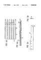
- FIG. 1 is a schematic side view of the whole structure of one embodiment of the present invention, showing only one side of a center line.
- FIG. 2a and 2b show a lower needle bed base, FIG. 2a being a longitudinal side view, FIG. 2b being an enlarged plan view of a head.
- FIGS. 3a, 3b and 3c are a side view and a sectional view of a lower needle plate, FIG. 3a showing an example having an upper needle bed base supporting member, FIG. 3b showing an example having no upper needle bed base supporting member, and FIG. 3c being a sectional view taken on line C--C of FIG. 3a.
- FIGS. 4a and 4b show an upper needle bed base, FIG. 4a being a longitudinal side view, and FIG. 4b being an enlarged plan view of a head.
- FIG. 5a is a side view of an upper needle plate
- FIG. 5b is a front view of the same.
- FIG. 6 is a sectional view taken on line VI--VI of FIG. 9.
- FIG. 7 is a sectional view taken on line VII--VII of FIG. 9.
- FIG. 8 is a sectional view taken on line VIII--VIII of FIG. 9.
- FIG. 9 is a sectional view taken on line IX--IX of FIG. 6.
- FIGS. 10a and 10b show a sinker jack, FIG. 10a being a side view, and FIG. 10b being a bottom view.
- FIG. 11 is a side view of a sinker jack.
- FIG. 12 is a side view of a sinker space.
- FIGS. 13a, 13b and 13c show a knockover bit, FIG. 13a being a plan view, FIG. 13b being a side view, and FIG. 13c being a back view.
- FIG. 14 is a schematic side view of the whole structure of another embodiment, showing only one side of a center line.
- FIG. 15a is a side view of a needle plate
- FIG. 15b is a sectional view taken on line B--B of FIG. 2B.
- FIG. 16 is a side view of a needle plate spacer.
- FIG. 17 is a plan view of a continuous -shaped comb.
- FIG. 18 is a front view of a beam fixing portion.
- FIG. 19 is a sectional view taken on line XIX--XIX of FIG. 20.
- FIG. 20 is a sectional view taken on line XX--XX of FIG. 19.
- FIGS. 21a and 2lb show a sinker jack, FIG. 21a being a side view, and FIG. 21b being a bottom view.
- FIG. 22 is a side view of a sinker jack.
- FIG. 23 is a side view of a sinker spacer.
- the knitting machine according to the present invention is a knitting machine of a 4-bed system in which an upper needle bed 2 is supported above a lower needle bed 1 having extreme ends opposed in angle.
- the machine is symmetrical to left and right about a center line X--X which passes through a tooth portion on which tops of the needle beds 1 and 2 are concentrated (see FIG. 1).
- the upper needle bed 2 is supported by a lower needle plate 3A of the lower needle bed 1.
- a lower needle bed base 4 is provided with a plurality of needle plate grooves 5 similar to the conventional needle bed. Needle plates 3A and 3B are fitted in the lower portion of the groove 5, both of which are fixed, for example, by passing a wire 9 through notches 7 and 8 provided in the needle bed base 4 and the lower needle plates 3A and 3B, respectively.
- the lower needle plate 3A is a plate-like member composed of a lower needle guide portion 10 extending from a head to a tail of the lower needle bed 1, an upper needle supporting member 11 of an extended portion which extends above the head and an upper needle bed base supporting member 12 positioned on the upper edge of a rear needle plate, as shown in FIG.
- a supporting surface 20 for supporting an upper needle bed base 19 is obliquely provided on the upper needle bed base supporting member 12, and a wedge-like notch 21 is provided on the extension of the supporting surface 20.
- the lower needle plate 3B shown in FIG. 3b has a construction in which the upper needle bed base supporting member 12 of the extension portion which extends above the head in the lower needle plate 3A is removed.
- the lower needle plates 3A and 3B are inserted into the needle plate groove 5 of the lower needle bed base 4 alternately or in a ratio of one needle plate 3A every two or three needle plates 3B, the lower needle bed base 4 and the needle plates 3A and 3B are fixed as previously mentioned, and a needle groove 22 is formed between the lower needle plates 3A and 3B.
- a lower needle 23 is slidably inserted into the needle groove 22.
- the upper needle bed 2 is secured to the lower needle bed 1 by a fixing member in the procedure mentioned below.
- the fixing member 13 comprises engaging means comprising a wedge-like head 24 and a wedge-like notch 25 for engagement between the upper needle bed base 19 and the upper needle bed base supporting member 12 of the lower needle plate 3A, and stop and fixing means including a stopping member 26.
- the upper needle bed base 19 is placed on the supporting surface 20 of the upper needle bed supporting member 12 of the lower needle plate 3A, and the wedge-like head 24 at the extreme end of the upper needle bed base 19 is placed in contact with the wedge-like notch 21 of the lower needle plate 3A.
- a notch 25 is provided at a position of the upper needle bed base 19 opposed to the end of the upper needle bed base supporting member 12, a wedge-like end 27 at one end of a wedge-like stopping member 26 extending widthwise of knitting of the knitting machine is brought into engagement with the notch 25, and the other end thereof is placed in contact with the upper needle bed base supporting member 12 of the lower needle plate 3A.
- a bolt 29 is threadedly engaged between the fixed beam 14 extending widthwise of the knitting beds inserted into the fixed beam insert hole 15 of the lower needle plate 3A and the stopping member 26, and the bolt 29 is tightened whereby a dove tail portion 30 between the wedge-like head 24 and the notch 25 of the upper needle bed base 19 is clamped by the wedge-like notch 21 of the lower needle plate 3A and the wedge-like end 27 of the stopping member 26 to secure the upper needle bed base 19 onto the lower needle plate 3A.
- the upper needle bed base 19 and the upper needle plate 33 are shown in FIG. 4 and FIG. 5, respectively.
- a needle plate groove 32 is provided in the upper needle bed base 19 in the same pitch and the same phase as that of the lower needle bed base 4, and an upper needle plate 33 is inserted therein.
- the upper needle supporting member 11 of the lower needle plates 3A and 3B has exactly the same shape.
- a sinker spacer 41, a sinker 42, a sinker jack 43, a knock over bit 44, etc. are provided on the upper needle supporting member 11. The details therefor will be described with reference to FIGS. 2, 3 and 6 to 13.
- the sinker spacer 41 is located at a shoulder 45 provided on the upper needle supporting member of the lower needle plates 3A and 3B.
- the sinker spacer 41 (FIG. 12) has an inverted U-shaped wire insert notch 46 at a lower portion of the tail, an engaging recess 48 for inserting a strap 47 for fixing a needle plate spacer 67 at the upper edge, and a bent element 49 for keeping a lower needle 23 at the end edge extending downwardly of the head.
- the sinker spacer 41 has a wire insert notch 46 at the tail located at an enlarged shoulder 50 (FIGS. 3 and 6) of the upper needle supporting member 11 so that the notch 46 is brought into engagement with a wire 1 inserted into a wire insert hole 18B ranging the lower needle. Plates 3A and 3B.
- a depressed portion 52 at the lower part of the head is brought into engagement with a wire 52 similar to the former and secured to the upper needle supporting member 11.
- a clearance is formed between the sinker spacer 41 and the top of the upper supporting member 11 by a top shoulder 54 (FIG. 3c) of the upper needle supporting member 11, and a sinker jack 43 is inserted therein (FIG. 7).
- the shoulder 54 is provided to be extended to the extreme end of the head of the lower needle plates 3A and 3B, and the sinker 42 is fitted in the extreme end portion of the head.
- the sinker jack 43 is in the form of an elongated plate as shown in FIG.
- a butt 55 is formed at a head with a downward engaging recess 56.
- the engaging concave 56 is brought into engagement with an engaging convex 57 provided on the upper edge of the sinker 42.
- the sinker 42 is also inserted into the same clearance formed by the shoulder 54 at the extreme end of the head of the lower needle plates 3A and 3B, and a rocking shaft 58 provided on the tail is fitted in a sinker supporting hole 16 provided in the head of the lower needle plates 3A and 3B and bored in contact with a shoulder at the extreme end of the head continuous to a top shoulder 54 so that the sinker 42 is rockably supported.
- the sinker 42 has angular portions 59, 60 and 61 in contact with a sinker loop vertically of the head.
- a guide recess 64 On the side of the upper needle supporting member 11 opposite to the shoulder 15 is provided a guide recess 64 in which a loop transfer blade 63 of the upper needle 38 is moved and slidably moved, and a knockover bit 44 is slidably provided on the side of the guide recess 64 while being placed on the wires 51 and 53.
- the knock-over bit 44 is provided a butt 66 at a tail of a flat-plate like shank 65 on which the upper needle 38 is placed and a square loop keep 67 at the head.
- a hook 68 of the upper needle 38 is located above the loop keep 67.
- a cam of a carriage not shown is placed in contact with the butt 66 of the knockover bit 44 so that it may be moved forward and backward along the upper needle 38.
- the butt 66 of the knockover bit 44 and the butt 55 of the sinker jack 43 are fitted into the clearance of the upper needle supporting member 11 with comb-like needle plate spacers 67 juxtaposed so that the positions thereof can be held accurately to maintain the spacing accurately.
- the needles of the beds 1 and 2 are operated by cams (not shown) on the carriages corresponding to the lower needle bed 1 and the upper needle bed 2, respectively, and in the upper needle bed 2, the knockover bit 44 is moved forward and backward together with the upper needle 38 according to the operation of the lower needle to prevent the lower needle 22 from being impaired in forward and backward movement.
- the needle plates are inserted into plural rows of needle plate grooves provided in the lower needle head base, and the needle groove is formed between the needle plates to form the needle bed, in which a part of the lower needle plate is extended upwardly, said extended portion serves as the upper needle bed supporting member, the fixing member for stopping the upper needle bed base is provided on the upper needle bed supporting member and the upper needle bed base is supported above the lower needle bed by the upper needle bed supporting member.
- the upper needle bed is to be supported on the needle bed base by the needle plate of the lower needle bed.
- the upper needle bed base is to be supported from the bottom with extremely high density to prevent an occurrence of the situation in which the central portion is hung down by the weight of the needle bed itself to curve the bed itself.
- FIG. 14 shows an example in which a lower needle bed 101 arranged in the form of an inverted V-shape symmetrically to left and right and an upper needle bed 102 arranged in the form of an inverted V-shape symmetrically to left and right thereabove are cut by a center line X--X, thus showing the left half thereof.
- needle plates 105 are inserted and fitted in plural rows of needle plate grooves 104 provided on a needle bed base 103 to form a needle groove 106 between the needle plates 105, both of which are fixed, for example, by passing a wire 109 through notches 107 and 108 provided in the needle bed groove base 103 and the needle plate 105.
- the needle plate 105 is a plate-like member composed of a lower needle groove wall 110 extending from a head to a tail of the lower needle bed 101, an extension portion 111 extending above the head, and an upper needle groove wall 112 reaching an upper level of the lower needle groove wall 110 extending rearward, as shown in FIG. 15.
- a dove tail 113 and a hook 114 to serve as a fixing member when the needle plates 105 are juxtaposed are projected downwardly at the lower portion of the upper needle groove wall portion 112.
- the needle plate 105 is provided with wire insert holes 116, 117 and 118 for stopping a needle plate spacer 115 and wire insert holes 119 for stopping upper and lower needles a jack, etc.
- a plurality of the needle plates 105 are inserted into the needle plate grooves 104 of the lower needle bed base 103 to fix the lower needle bed base 103 and the needle plates 105 as mentioned above to form the needle groove 106 between the needle plates 105 and 105.
- a lower needle 120 is slidably inserted into the needle groove 106.
- the upper needle bed 102 is provided above the lower needle bed 101 in the following procedure.
- the needle plates 105 are fitted in the needle plate grooves 104 provided in row in the needle bed base 103 of the lower needle bed 101, fixed by the wire 109 and caulked at the end together with the needle bed base 103.
- a needle plate spacer 115 is provided within a clearance between the upper needle groove walls 112 adjacent to each other of the juxtaposed needle plates 105.
- the needle plate spacer 115 has a hook 121 at the extreme end being stopped at a wire 122 inserted into a wire insert hole 116 of the needle plate 105.
- a hook 123 provided at the tail end is stopped at a wire 124 inserted into a wire insert hole 118 of the needle plate 105, and the needle plate spacer 115 is held between the needle plates 105 and 105 in the state where the central portion is placed on a wire 125 inserted into a wire insert hole 117.
- a continuous comb 126 is fitted in the hook 114 at the tail end of the needle plates 105 and 105 (see FIG. 17).
- a pawl 129 of a beam 128 having an L-shape in section is stopped at one inclined surface 127 of the dove tail 113 projected at the lower portion of the upper needle groove wall 112, the needle plates 105 are fitted in comb-like clearances 130 provided in a riser portion of the beam 128, a wire 132 is interposed between the inclined surface 131 of the dove tail 113 and the riser portion, and the wire 132 is threadedly mounted at suitable intervals and tightened by a screw 133 whereby a spacing between the needle plates 105 and 105 is maintained accurately to constitute the upper needle bed 102.
- a needle groove 134 of the upper needle bed 102 is formed between the needle plates 105 and 105, and an upper needle 135 is inserted therein.
- the needle plate 105 is provided with a sinker supporting hole 136 for rockably supporting a sinker 142 which will be described later.
- the needle spacer 115 is not extended to the neighbourhood of the head of the needle plate 105.
- a sinker spacer 141, a sinker 142, a sinker jack 143, a knockover bit 144, etc. are provided from the extreme end of the needle spacer 115 to a position opposed to the head of the lower needle bed 101. The details therefor will be described with reference to FIGS. 14 and 18 to 23.
- the sinker spacer 141 is positioned at a shoulder 145 (see FIG. 15b) provided on the head of the upper needle groove wall 112 of the needle plate 105.
- the sinker spacer 141 (FIG. 23) has an inverted U-shaped wire insert notch 146 at the lower portion of the tail, an engaging recess 148 into which is inserted a strap 147 at the upper edge, and a bended element 149 for holding the lower needle 120 at the end edge extending downwardly of the head.
- the sinker spacer 141 is positioned at an enlarged shoulder 150 (see FIG.
- a clearance is formed between the sinker spacer 141 and the top of the upper needle groove wall 112 by a top shoulder 154 (FIG. 15b) of the upper needle groove wall 112, and the sinker jack 143 is inserted therein (FIG. 19).
- the shoulder 154 extends to the extreme end of the head of the needle plate 105, and the sinker 142 described later is fitted in said extreme end of the head.
- the sinker jack 143 is in the form of an elongated plate as shown in FIG.
- a butt 155 and a downward engaging concave 156 are formed in the upper portion and the head, respectively.
- the engaging recess 156 is engaged with an engaging convex 157 provided on the upper edge of the sinker 142.
- the sinker 142 is also inserted into the same clearance formed by the shoulder 154 at the extreme end of the head of the needle plate 105, and a rockable shaft 158 provided on the tail is fitted in a sinker supporting hole 136 provided in the head of the needle plate 105 and bored in contact with a shoulder at the extreme end of the head continuous to the top shoulder 154 to rockably support the sinker 142.
- the sinker 142 has angular portions 159, 160 and 161 having a sinker loop in a vertical direction of the head.
- a guide recess 164 into which is moved and slidably moved a loop transfer blade 163 of the upper needle 135 is provided in the side of the upper needle groove wall 112 of the needle plate 105 opposite to the shoulder 145, and the knockover bit 144 is slidably provided on the guide recess 164 side (FIG. 15b and FIG. 21) in the state where the wires 151 and 153 are placed thereon as shown in FIG. 20.
- the knockover bit 144 has a butt 166 at the tail of a flat plate-like shank 165 with the upper needle 135 placed thereon, and a square loop keep 167 at the head.
- a hook 168 of the upper needle 135 is positioned above the loop keep 167.
- a cam of a carriage not shown comes into contact with the butt 166 of the knockover bit 144 to enable forward and backward movement along the upper needle 135.
- the butt 166 of the knockover bit 144 and the butt 155 of the sinker jack 143 are fitted into the clearance of the upper needle groove wall 112 with comb-like needle plate spacers 169 juxtaposed so as to accurately hold their position to accurately maintain the spacing therebetween.
- the needles of both the beds 101 and 102 are operated by cams (not shown) of carriages corresponding to the lower needle bed 101 and the upper needle bed 102.
- the knockover bit 144 together with the upper needle 135 are moved forward and backward according to the operation of the lower needle 120 to prevent the lower needle 120 from being impeded in forward and backward movement thereof.
- the needle plates fitted in the needle plate grooves provided in plural rows on the lower needle bed base are extended upwardly to form the upper needle groove wall, the needle plate spacer is held between the needle plates of the upper needle groove wall, and the upper needle bed is constituted by the upper groove wall and the needle plate spacer.
- the upper needle bed and the lower needle bed become integral with the needle plates to support the upper needle bed. Therefore, an angle formed by the upper and lower needle beds is constant when assembled, and the angle need not be adjusted and the angle is not varied during use.
- the upper needle bed is integral with the lower needle bed over the whole width of the knitting machine, it is possible to prevent an occurrence of the situation wherein a flexure is generated in the upper needle bed by being pressed by the carriage, or an occurrence of the situation wherein the central portion is hung down by the weight of the needle bed itself to curve the bed itself.
Landscapes
- Engineering & Computer Science (AREA)
- Textile Engineering (AREA)
- Knitting Machines (AREA)
Applications Claiming Priority (4)
| Application Number | Priority Date | Filing Date | Title |
|---|---|---|---|
| JP3-173263 | 1991-06-18 | ||
| JP3173263A JP2687190B2 (ja) | 1991-06-18 | 1991-06-18 | 二段ベッド横編機 |
| JP3-237247 | 1991-08-23 | ||
| JP23724791A JPH0796742B2 (ja) | 1991-08-23 | 1991-08-23 | 二段ベッド横編機 |
Publications (1)
| Publication Number | Publication Date |
|---|---|
| US5369965A true US5369965A (en) | 1994-12-06 |
Family
ID=26495317
Family Applications (1)
| Application Number | Title | Priority Date | Filing Date |
|---|---|---|---|
| US07/898,088 Expired - Lifetime US5369965A (en) | 1991-06-18 | 1992-06-12 | Upper needle bed support for V-bed knitting machine |
Country Status (5)
| Country | Link |
|---|---|
| US (1) | US5369965A (it) |
| EP (1) | EP0519652B1 (it) |
| DE (1) | DE4220191C2 (it) |
| ES (1) | ES2088547T3 (it) |
| IT (1) | IT1254390B (it) |
Cited By (6)
| Publication number | Priority date | Publication date | Assignee | Title |
|---|---|---|---|---|
| US5557948A (en) * | 1994-04-28 | 1996-09-24 | Shima Seiki Mfg. Ltd. | Yarn guiding method and apparatus for flat knitting machine |
| US5802878A (en) * | 1995-06-15 | 1998-09-08 | Shima Seiki Manufacturing, Ltd. | Needle selection device of flat knitting machine |
| US5806347A (en) * | 1996-09-05 | 1998-09-15 | Matec S.R.L. | Modified sub-needle with associated actuation elements for circular knitters |
| CN100554555C (zh) * | 2004-12-09 | 2009-10-28 | 株式会社岛精机制作所 | 横编机 |
| US20090310772A1 (en) * | 2006-07-10 | 2009-12-17 | New I.P. Investments, Llc | Systems and methods for providing answering services |
| CN109825940A (zh) * | 2019-03-14 | 2019-05-31 | 桐乡市巨星针织机械制造有限公司 | 一种多层插片及包含多层插片的复合针床 |
Families Citing this family (3)
| Publication number | Priority date | Publication date | Assignee | Title |
|---|---|---|---|---|
| JP2726959B2 (ja) * | 1991-08-29 | 1998-03-11 | 株式会社島精機製作所 | 横編地の編成方法及び多段ベッド横編機 |
| JP2628128B2 (ja) * | 1992-12-17 | 1997-07-09 | 株式会社島精機製作所 | 横編機 |
| JP5695964B2 (ja) * | 2011-04-28 | 2015-04-08 | 株式会社島精機製作所 | 横編機 |
Citations (4)
| Publication number | Priority date | Publication date | Assignee | Title |
|---|---|---|---|---|
| US750052A (en) * | 1904-01-19 | Peters co | ||
| GB190526249A (en) * | 1905-12-16 | 1906-12-13 | Franz Anton | Improved Method of Producing on Knitting Machines, Tubular Hosiery with Weft-threads. |
| US4100766A (en) * | 1974-07-29 | 1978-07-18 | Universal Maschinenfabrik Dr. Rudolf Schieber Kg | Flat knitting machine having four opposed needle beds |
| US4905483A (en) * | 1987-09-04 | 1990-03-06 | Shima Seiki Mfg. Ltd. | Flat knitting machine |
Family Cites Families (4)
| Publication number | Priority date | Publication date | Assignee | Title |
|---|---|---|---|---|
| DE141299C (it) * | ||||
| FR1073501A (fr) * | 1953-01-08 | 1954-09-27 | Procédé et dispositif pour la fabrication de tricot élastique circulaire | |
| FR1098776A (fr) * | 1953-02-13 | 1955-08-22 | Machine à tricoter | |
| DE2728223C3 (de) * | 1977-06-23 | 1980-10-30 | Hans 8581 Mistelbach Maisel | Nadelbett für Flachstrick- und -Wirkmaschinen |
-
1992
- 1992-06-11 EP EP92305389A patent/EP0519652B1/en not_active Expired - Lifetime
- 1992-06-11 ES ES92305389T patent/ES2088547T3/es not_active Expired - Lifetime
- 1992-06-12 US US07/898,088 patent/US5369965A/en not_active Expired - Lifetime
- 1992-06-17 IT ITRM920459A patent/IT1254390B/it active
- 1992-06-19 DE DE4220191A patent/DE4220191C2/de not_active Expired - Lifetime
Patent Citations (4)
| Publication number | Priority date | Publication date | Assignee | Title |
|---|---|---|---|---|
| US750052A (en) * | 1904-01-19 | Peters co | ||
| GB190526249A (en) * | 1905-12-16 | 1906-12-13 | Franz Anton | Improved Method of Producing on Knitting Machines, Tubular Hosiery with Weft-threads. |
| US4100766A (en) * | 1974-07-29 | 1978-07-18 | Universal Maschinenfabrik Dr. Rudolf Schieber Kg | Flat knitting machine having four opposed needle beds |
| US4905483A (en) * | 1987-09-04 | 1990-03-06 | Shima Seiki Mfg. Ltd. | Flat knitting machine |
Cited By (6)
| Publication number | Priority date | Publication date | Assignee | Title |
|---|---|---|---|---|
| US5557948A (en) * | 1994-04-28 | 1996-09-24 | Shima Seiki Mfg. Ltd. | Yarn guiding method and apparatus for flat knitting machine |
| US5802878A (en) * | 1995-06-15 | 1998-09-08 | Shima Seiki Manufacturing, Ltd. | Needle selection device of flat knitting machine |
| US5806347A (en) * | 1996-09-05 | 1998-09-15 | Matec S.R.L. | Modified sub-needle with associated actuation elements for circular knitters |
| CN100554555C (zh) * | 2004-12-09 | 2009-10-28 | 株式会社岛精机制作所 | 横编机 |
| US20090310772A1 (en) * | 2006-07-10 | 2009-12-17 | New I.P. Investments, Llc | Systems and methods for providing answering services |
| CN109825940A (zh) * | 2019-03-14 | 2019-05-31 | 桐乡市巨星针织机械制造有限公司 | 一种多层插片及包含多层插片的复合针床 |
Also Published As
| Publication number | Publication date |
|---|---|
| ES2088547T3 (es) | 1996-08-16 |
| ITRM920459A0 (it) | 1992-06-17 |
| EP0519652B1 (en) | 1996-04-24 |
| DE4220191A1 (de) | 1992-12-24 |
| EP0519652A1 (en) | 1992-12-23 |
| DE4220191C2 (de) | 1996-08-29 |
| IT1254390B (it) | 1995-09-14 |
| ITRM920459A1 (it) | 1993-12-17 |
Similar Documents
| Publication | Publication Date | Title |
|---|---|---|
| US5369965A (en) | Upper needle bed support for V-bed knitting machine | |
| US5333473A (en) | Sinker mechanism for flat knitting machines | |
| US6895784B2 (en) | Device for machine knitting | |
| US4157690A (en) | Needle bar for a tufting machine | |
| JP2694626B2 (ja) | 横編機 | |
| EP0717797B1 (en) | Device for holding down the stitches being formed in a flat knitting machine | |
| US6014874A (en) | Yarn guide for weft knitting machine | |
| US4840133A (en) | Needle plate for hook bar of cut pile tifting machine | |
| EP0698679B1 (en) | Knitting cam and cam apparatus | |
| JP2687190B2 (ja) | 二段ベッド横編機 | |
| JP2726959B2 (ja) | 横編地の編成方法及び多段ベッド横編機 | |
| JP2709540B2 (ja) | 二段ベッド横編機における上部ベッドの支持固定方法 | |
| US4649721A (en) | Knitting instrument carrier for knitting machines | |
| JPH0559644A (ja) | 二段ベツド横編機 | |
| JP4519636B2 (ja) | 可動シンカを備える横編機 | |
| US2873595A (en) | Instrument beds for knitting machines | |
| JPH0559645A (ja) | 二段ベツド横編機 | |
| JPH0796740B2 (ja) | 二段ベッド横編機におけるシンカー | |
| US4557119A (en) | Carriage for a hand-operated single bed knitting machine | |
| JPH0796741B2 (ja) | 多段式横編機におけるシンカー | |
| US3541813A (en) | Needle for warp knitting machines | |
| RU227395U1 (ru) | Узел каретки и иглы вязальной машины | |
| JPS6217505Y2 (it) | ||
| JPS641973Y2 (it) | ||
| JPS6038703Y2 (ja) | 編機のジヤツク選択装置 |
Legal Events
| Date | Code | Title | Description |
|---|---|---|---|
| AS | Assignment |
Owner name: SHIMA SEIKI MFG. LTD., JAPAN Free format text: ASSIGNMENT OF ASSIGNORS INTEREST.;ASSIGNORS:SHIMA, MASAHIRO;YABUTA, MASAHIRO;NAKAMORI, TOSHINORI;AND OTHERS;REEL/FRAME:006156/0825 Effective date: 19920604 |
|
| STCF | Information on status: patent grant |
Free format text: PATENTED CASE |
|
| FEPP | Fee payment procedure |
Free format text: PAYOR NUMBER ASSIGNED (ORIGINAL EVENT CODE: ASPN); ENTITY STATUS OF PATENT OWNER: LARGE ENTITY |
|
| FPAY | Fee payment |
Year of fee payment: 4 |
|
| FPAY | Fee payment |
Year of fee payment: 8 |
|
| FPAY | Fee payment |
Year of fee payment: 12 |