US5371959A - Pointing device carried by digging arm of excavator, for dynamically indicating location and direction of extension of underground cable - Google Patents
Pointing device carried by digging arm of excavator, for dynamically indicating location and direction of extension of underground cable Download PDFInfo
- Publication number
- US5371959A US5371959A US07/916,110 US91611092A US5371959A US 5371959 A US5371959 A US 5371959A US 91611092 A US91611092 A US 91611092A US 5371959 A US5371959 A US 5371959A
- Authority
- US
- United States
- Prior art keywords
- pointer
- underground cable
- elongated pointer
- digging arm
- cable
- Prior art date
- Legal status (The legal status is an assumption and is not a legal conclusion. Google has not performed a legal analysis and makes no representation as to the accuracy of the status listed.)
- Expired - Fee Related
Links
- 238000009412 basement excavation Methods 0.000 claims description 2
- 239000003550 marker Substances 0.000 claims 3
- 230000035807 sensation Effects 0.000 claims 2
- 230000000007 visual effect Effects 0.000 claims 1
- 239000004020 conductor Substances 0.000 abstract description 4
- 229910052751 metal Inorganic materials 0.000 description 3
- 239000002184 metal Substances 0.000 description 3
- 238000000034 method Methods 0.000 description 3
- 239000004411 aluminium Substances 0.000 description 2
- 229910052782 aluminium Inorganic materials 0.000 description 2
- XAGFODPZIPBFFR-UHFFFAOYSA-N aluminium Chemical compound [Al] XAGFODPZIPBFFR-UHFFFAOYSA-N 0.000 description 2
- XLYOFNOQVPJJNP-UHFFFAOYSA-N water Substances O XLYOFNOQVPJJNP-UHFFFAOYSA-N 0.000 description 2
- 230000006698 induction Effects 0.000 description 1
- 230000003287 optical effect Effects 0.000 description 1
- 238000010561 standard procedure Methods 0.000 description 1
Images


Classifications
-
- E—FIXED CONSTRUCTIONS
- E02—HYDRAULIC ENGINEERING; FOUNDATIONS; SOIL SHIFTING
- E02F—DREDGING; SOIL-SHIFTING
- E02F9/00—Component parts of dredgers or soil-shifting machines, not restricted to one of the kinds covered by groups E02F3/00 - E02F7/00
- E02F9/26—Indicating devices
-
- G—PHYSICS
- G01—MEASURING; TESTING
- G01V—GEOPHYSICS; GRAVITATIONAL MEASUREMENTS; DETECTING MASSES OR OBJECTS; TAGS
- G01V3/00—Electric or magnetic prospecting or detecting; Measuring magnetic field characteristics of the earth, e.g. declination, deviation
- G01V3/02—Electric or magnetic prospecting or detecting; Measuring magnetic field characteristics of the earth, e.g. declination, deviation operating with propagation of electric current
- G01V3/06—Electric or magnetic prospecting or detecting; Measuring magnetic field characteristics of the earth, e.g. declination, deviation operating with propagation of electric current using AC
-
- Y—GENERAL TAGGING OF NEW TECHNOLOGICAL DEVELOPMENTS; GENERAL TAGGING OF CROSS-SECTIONAL TECHNOLOGIES SPANNING OVER SEVERAL SECTIONS OF THE IPC; TECHNICAL SUBJECTS COVERED BY FORMER USPC CROSS-REFERENCE ART COLLECTIONS [XRACs] AND DIGESTS
- Y10—TECHNICAL SUBJECTS COVERED BY FORMER USPC
- Y10S—TECHNICAL SUBJECTS COVERED BY FORMER USPC CROSS-REFERENCE ART COLLECTIONS [XRACs] AND DIGESTS
- Y10S37/00—Excavating
- Y10S37/906—Visual aids and indicators for excavating tool
Definitions
- the present invention relates to a pointer for attachment to the digging arm of a mechanical excavator or digging machine, or to some other appropriate part of said machine.
- Valuable assets are lost annually as a result of severing or destroying underground cables and underground conductors during ground excavating work carried out with the aid of excavating or digging machines.
- no effective method has been proposed which will enable the extension of underground cables, etc., to be detected and marked-out before commencing the excavation work.
- the presence of an underground cable has been localized by detecting its magnetic field in accordance with standard methods and determining the position and the geometric extension of the cable on the basis thereof. The extension of the cable is then marked with the aid of pegs driven into the ground.
- the object of the present invention is to provide a pointer which will constantly point to or indicate the location of an underground cable during an excavating operation, so that the machine operator can avoid cutting through or digging-up the cable or conduit.
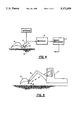
- FIG. 1 illustrates schematically the pointer attached to the digging arm of an excavating machine
- FIG. 2 illustrates schematically a detail of the invention
- FIG. 3 is a schematic sectional view of the detail illustrated in FIG. 2;
- FIGS. 4 and 5 are schematic illustrations of the working method of the device.
- FIGS. 4 and 5 illustrate the method of operation of the invention schematically.
- a digging arm 2 of an excavating machine 1 carries a bucket 3 which is equipped with a pointer 4 constructed in accordance with the invention.
- the reference numeral 5 identifies an underground cable.
- the pointer 4 has the form of an elongated arm which can be swung about an axle which extends generally at right angles the plane of the paper, by means of a drive means.
- a receiver 6 receives and converts the signals produced by an antenna system mounted on the pointer 4, the signals received deriving from the magnetic field generated by the cable 5.
- the receiver output signals are processed in computers and are used to control drive means, in the form of a servomechanism 7, in a manner to position the pointer in the direction in which the strongest magnetic field is detected, i.e. towards the cable 5.
- control drive means in the form of a servomechanism 7, in a manner to position the pointer in the direction in which the strongest magnetic field is detected, i.e. towards the cable 5.
- the cable 5 is not current-conducting or consists of an optocable, which is normally provided with a metal screen or an aluminium strip, or when the underground object is a water pipe instead of a cable 5, there is used a transmitter for generating a magnetic field whereby an electric current can be induced in the non-conducting cable, the optocable or the water pipe, and the magnetic field generated by this current can be detected in the aforedescribed manner.
- the transmitter is preferably mounted on the excavating machine.
- FIG. 1 illustrates schematically and in more detail the pointer 4 mounted on the digging arm 2 by means an axle 9 about which the pointer can be swung or pivoted.
- the pointer 4 In its upwardly swung position, its inactive position, shown in broken lines, the pointer 4 is conveniently positioned beneath a robust metal shield which protects the pointer against damage.
- the pointer of the illustrated embodiment comprises two parts, i.e. an upper part 10 which is pivotal on the axle 9, and a lower part 11 which is pivotal relative to the upper part 10 on a further axle 12, as described in more detail herebelow with reference to FIGS. 2 and 3.
- FIG. 2 illustrates schematically the pointer 4 provided with drive means in the form of two servomotors.
- One servomotor, 13, is connected to the axle 9 through the intermediary of a worm gear 14.
- the servo motor 13 thus controls the movement of the pointer 4 on the axle 9 so as to direct the pointer constantly towards the cable 5 during the active function of the pointer.
- the pointer comprises two parts and is provided with a marking at its outer, free end.
- the end of the pointer may thus be flattened, for instance in a wedge-shape, and provided with an enlarged plate--flag--provided with a colour marking or the like, not shown, so as to obtain a direction indication.
- the axle 12 is therefore driven by a servomotor 15, through the intermediary of a gear 16, and the axle in turn rotates the lower part 11 of the pointer 4.
- the characteristics of the magnetic field generated by the cable 5 and indicating the length extension of the cable are also recorded in the receiver 6, which controls the servomotor 15 in a manner such as to rotate the lower pointer-part 11 to a position in which the marking will point to or indicate the direction of the cable.
- the invention enables the machine operator to constantly be aware of the location of an underground cable and also the length extension of the cable. This enables the machine operator to avoid digging-up the cable.
- axle 9 need not extend perpendicularly to the digging arm 2 (perpendicular to the plane of the paper in FIG. 1), but may instead be inclined relative to the digging arm. The most essential factor is that the machine operator is able to clearly discern the movements made by the pointer and to see the directions in which the pointer points.
- the servo motors for effecting movement of the pointer may suitably be driven electrically or hydraulically.
Landscapes
- Engineering & Computer Science (AREA)
- Life Sciences & Earth Sciences (AREA)
- Remote Sensing (AREA)
- Physics & Mathematics (AREA)
- Structural Engineering (AREA)
- Civil Engineering (AREA)
- Environmental & Geological Engineering (AREA)
- Geology (AREA)
- Mining & Mineral Resources (AREA)
- General Engineering & Computer Science (AREA)
- General Life Sciences & Earth Sciences (AREA)
- General Physics & Mathematics (AREA)
- Geophysics (AREA)
- Excavating Of Shafts Or Tunnels (AREA)
- Earth Drilling (AREA)
- Geophysics And Detection Of Objects (AREA)
Applications Claiming Priority (3)
| Application Number | Priority Date | Filing Date | Title |
|---|---|---|---|
| SE9004002-3 | 1990-12-14 | ||
| SE9004002A SE467978B (sv) | 1990-12-14 | 1990-12-14 | Pekare |
| EP19910850310 EP0490855B1 (de) | 1990-12-14 | 1991-12-11 | Anzeiger |
Publications (1)
| Publication Number | Publication Date |
|---|---|
| US5371959A true US5371959A (en) | 1994-12-13 |
Family
ID=26130347
Family Applications (1)
| Application Number | Title | Priority Date | Filing Date |
|---|---|---|---|
| US07/916,110 Expired - Fee Related US5371959A (en) | 1990-12-14 | 1991-12-11 | Pointing device carried by digging arm of excavator, for dynamically indicating location and direction of extension of underground cable |
Country Status (2)
| Country | Link |
|---|---|
| US (1) | US5371959A (de) |
| AT (1) | ATE104719T1 (de) |
Cited By (10)
| Publication number | Priority date | Publication date | Assignee | Title |
|---|---|---|---|---|
| US5479729A (en) * | 1994-04-04 | 1996-01-02 | At&T Corp. | Method and apparatus for controlling excavation eqiupment |
| US5684466A (en) * | 1995-09-12 | 1997-11-04 | The Charles Machine Work, Inc. | Electrical strike system control for subsurface boring equipment |
| US5815959A (en) * | 1997-04-28 | 1998-10-06 | Caterpillar Inc. | Bucket shaped for reduced heel wear |
| US5920194A (en) * | 1994-05-06 | 1999-07-06 | Radiodetection Limited | Device for locating objects that emit electromagnetic signals |
| US6091337A (en) * | 1999-03-15 | 2000-07-18 | Case Corporation | High voltage contact monitor with built-in self tester |
| US6336077B1 (en) * | 1999-06-07 | 2002-01-01 | BOUCHER GAéTAN | Automatic monitoring and display system for use with a diggins machine |
| US20030184300A1 (en) * | 2002-04-02 | 2003-10-02 | Bigelow Russell N. | underground locator with a laser marking device. |
| WO2008064852A3 (de) * | 2006-12-01 | 2009-01-08 | Leica Geosystems Ag | Lokalisierungssystem für eine geländebearbeitungsmaschine |
| US20120182016A1 (en) * | 2009-09-10 | 2012-07-19 | Bucyrus Europe Gmbh | Sensor device and method for the geoelectrical prospecting of raw mineral deposits |
| CN111565555A (zh) * | 2017-11-06 | 2020-08-21 | Brp集团私人有限责任公司 | 用于在挖掘期间检测地下电力电缆的存在的电磁频率(emf)检测安全铲 |
Citations (9)
| Publication number | Priority date | Publication date | Assignee | Title |
|---|---|---|---|---|
| US3418572A (en) * | 1966-02-11 | 1968-12-24 | Thomas G. Humphreys Jr. | Apparatus including variable frequency indicating means for locating and tracing conductive structures |
| US3617865A (en) * | 1968-05-25 | 1971-11-02 | Goroku Hakata | Method and apparatus for locating a buried metallic line employing magnetic field gradient measurements |
| US3858737A (en) * | 1971-12-02 | 1975-01-07 | Rikizo Senoo | Excavator |
| US3916298A (en) * | 1973-07-11 | 1975-10-28 | Scott Allison E | System utilizing galvanic potentials for detecting buried conductive structures |
| EP0046854A1 (de) * | 1980-08-30 | 1982-03-10 | Friedrich Wilh. Schwing GmbH | Vorrichtung zur Kontrolle der Schürfeinrichtung eines Löffelbaggers, insbesondere mit einer Parallelführung des auf einen vorgegebenen Schnittwinkel eingestellten Löffels |
| US4600356A (en) * | 1984-01-27 | 1986-07-15 | Gas Research Institute | Underground pipeline and cable detector and process |
| US4652861A (en) * | 1985-06-04 | 1987-03-24 | Gte Sprint Communications Corporation | Method and apparatus for protecting buried optical fiber cable |
| EP0388568A2 (de) * | 1988-12-30 | 1990-09-26 | Compagnie Francaise De Mokta | Schaltung zur Messung der Radioaktivität von Mineralien auf einer Fördermaschine, wie zum Beispiel einem Schaufelbagger |
| US5027108A (en) * | 1990-03-05 | 1991-06-25 | Gray Alden J | Buried power line contact alert |
-
1991
- 1991-12-11 AT AT9191850310T patent/ATE104719T1/de not_active IP Right Cessation
- 1991-12-11 US US07/916,110 patent/US5371959A/en not_active Expired - Fee Related
Patent Citations (9)
| Publication number | Priority date | Publication date | Assignee | Title |
|---|---|---|---|---|
| US3418572A (en) * | 1966-02-11 | 1968-12-24 | Thomas G. Humphreys Jr. | Apparatus including variable frequency indicating means for locating and tracing conductive structures |
| US3617865A (en) * | 1968-05-25 | 1971-11-02 | Goroku Hakata | Method and apparatus for locating a buried metallic line employing magnetic field gradient measurements |
| US3858737A (en) * | 1971-12-02 | 1975-01-07 | Rikizo Senoo | Excavator |
| US3916298A (en) * | 1973-07-11 | 1975-10-28 | Scott Allison E | System utilizing galvanic potentials for detecting buried conductive structures |
| EP0046854A1 (de) * | 1980-08-30 | 1982-03-10 | Friedrich Wilh. Schwing GmbH | Vorrichtung zur Kontrolle der Schürfeinrichtung eines Löffelbaggers, insbesondere mit einer Parallelführung des auf einen vorgegebenen Schnittwinkel eingestellten Löffels |
| US4600356A (en) * | 1984-01-27 | 1986-07-15 | Gas Research Institute | Underground pipeline and cable detector and process |
| US4652861A (en) * | 1985-06-04 | 1987-03-24 | Gte Sprint Communications Corporation | Method and apparatus for protecting buried optical fiber cable |
| EP0388568A2 (de) * | 1988-12-30 | 1990-09-26 | Compagnie Francaise De Mokta | Schaltung zur Messung der Radioaktivität von Mineralien auf einer Fördermaschine, wie zum Beispiel einem Schaufelbagger |
| US5027108A (en) * | 1990-03-05 | 1991-06-25 | Gray Alden J | Buried power line contact alert |
Cited By (15)
| Publication number | Priority date | Publication date | Assignee | Title |
|---|---|---|---|---|
| US5479729A (en) * | 1994-04-04 | 1996-01-02 | At&T Corp. | Method and apparatus for controlling excavation eqiupment |
| US5920194A (en) * | 1994-05-06 | 1999-07-06 | Radiodetection Limited | Device for locating objects that emit electromagnetic signals |
| US5684466A (en) * | 1995-09-12 | 1997-11-04 | The Charles Machine Work, Inc. | Electrical strike system control for subsurface boring equipment |
| US5815959A (en) * | 1997-04-28 | 1998-10-06 | Caterpillar Inc. | Bucket shaped for reduced heel wear |
| US6091337A (en) * | 1999-03-15 | 2000-07-18 | Case Corporation | High voltage contact monitor with built-in self tester |
| US6336077B1 (en) * | 1999-06-07 | 2002-01-01 | BOUCHER GAéTAN | Automatic monitoring and display system for use with a diggins machine |
| US20030184300A1 (en) * | 2002-04-02 | 2003-10-02 | Bigelow Russell N. | underground locator with a laser marking device. |
| WO2008064852A3 (de) * | 2006-12-01 | 2009-01-08 | Leica Geosystems Ag | Lokalisierungssystem für eine geländebearbeitungsmaschine |
| US20100052684A1 (en) * | 2006-12-01 | 2010-03-04 | Leica Geosystems Ag | Localization system for an earthmoving machine |
| AU2007324836B2 (en) * | 2006-12-01 | 2010-11-04 | Leica Geosystems Ag | Localization system for an earthmoving machine |
| US8164338B2 (en) | 2006-12-01 | 2012-04-24 | Leica Geosystems Ag | Localization system for an earthmoving machine |
| US20120182016A1 (en) * | 2009-09-10 | 2012-07-19 | Bucyrus Europe Gmbh | Sensor device and method for the geoelectrical prospecting of raw mineral deposits |
| US9051832B2 (en) * | 2009-09-10 | 2015-06-09 | Caterpillar Global Mining Europe Gmbh | Sensor device and method for the geoelectrical prospecting of raw mineral deposits |
| CN111565555A (zh) * | 2017-11-06 | 2020-08-21 | Brp集团私人有限责任公司 | 用于在挖掘期间检测地下电力电缆的存在的电磁频率(emf)检测安全铲 |
| CN111565555B (zh) * | 2017-11-06 | 2022-10-04 | Brp集团私人有限责任公司 | 用于在挖掘期间检测地下电力电缆的存在的电磁频率(emf)检测安全铲 |
Also Published As
| Publication number | Publication date |
|---|---|
| ATE104719T1 (de) | 1994-05-15 |
Similar Documents
| Publication | Publication Date | Title |
|---|---|---|
| US6833795B1 (en) | Underground utility detection system and method employing ground penetrating radar | |
| EP2095156B1 (de) | Lokalisierungssystem für eine geländebearbeitungsmaschine | |
| KR20190034282A (ko) | 건설 기계 | |
| SE436436B (sv) | Djupmetare vid grevmaskiner | |
| EP0645646B1 (de) | Anlage und Verfahren zum Auffinden von Kabeln | |
| US20140212222A1 (en) | Cable recovery device and system | |
| EP0490855B1 (de) | Anzeiger | |
| JPS6389736A (ja) | 土工作業機械の高さ表示装置 | |
| US5596826A (en) | Level indicating mechanism for a work machine | |
| CA2804867C (en) | Cable recovery device and system | |
| CN114207226B (zh) | 用于检测尤其在机器作业工具附近的物体轮廓的雷达系统 | |
| JPH06230141A (ja) | 地中探査装置付き掘削機 | |
| KR100250676B1 (ko) | 굴삭기의 굴삭깊이 측정장치 | |
| JP2857781B2 (ja) | 路面切断用カッター装置 | |
| JP7173627B2 (ja) | 建設機械 | |
| JPH08158770A (ja) | 埋設物探知装置に用いる探知刃構造 | |
| JPH0354197Y2 (de) | ||
| FR2411272A1 (fr) | Procede et machine automotrice pour creuser des tranchees sous l'eau | |
| JPH11148290A (ja) | 杭埋設孔を掘削するオ−ガスクリュ−の傾斜測定装置 | |
| JP2019207189A (ja) | 金属探査システムおよび金属探査方法 | |
| GB2065751A (en) | Deep water extractor | |
| KR20210044601A (ko) | 전력케이블 접지봉 매설 유도공 굴착장치 및 안전접지 시공방법 | |
| JP3813012B2 (ja) | レーダー付推進装置 | |
| JPH08166233A (ja) | 作業機の角度検出機構 | |
| JPH11159285A (ja) | レーダー付推進装置と掘削ルートの調査方法 |
Legal Events
| Date | Code | Title | Description |
|---|---|---|---|
| AS | Assignment |
Owner name: SERVOINDIKATOR HB, SWEDEN Free format text: ASSIGNMENT OF ASSIGNORS INTEREST.;ASSIGNOR:AHS, WILGOT;REEL/FRAME:006456/0456 Effective date: 19920604 |
|
| FEPP | Fee payment procedure |
Free format text: PAYOR NUMBER ASSIGNED (ORIGINAL EVENT CODE: ASPN); ENTITY STATUS OF PATENT OWNER: LARGE ENTITY |
|
| REMI | Maintenance fee reminder mailed | ||
| FPAY | Fee payment |
Year of fee payment: 4 |
|
| SULP | Surcharge for late payment | ||
| REMI | Maintenance fee reminder mailed | ||
| LAPS | Lapse for failure to pay maintenance fees | ||
| STCH | Information on status: patent discontinuation |
Free format text: PATENT EXPIRED DUE TO NONPAYMENT OF MAINTENANCE FEES UNDER 37 CFR 1.362 |
|
| FP | Lapsed due to failure to pay maintenance fee |
Effective date: 20021213 |