US5396040A - Device, standard blanks and standardized electrodes for electro-discharge milling - Google Patents
Device, standard blanks and standardized electrodes for electro-discharge milling Download PDFInfo
- Publication number
- US5396040A US5396040A US07/675,903 US67590391A US5396040A US 5396040 A US5396040 A US 5396040A US 67590391 A US67590391 A US 67590391A US 5396040 A US5396040 A US 5396040A
- Authority
- US
- United States
- Prior art keywords
- tool
- electrode
- holder
- machining
- touching
- Prior art date
- Legal status (The legal status is an assumption and is not a legal conclusion. Google has not performed a legal analysis and makes no representation as to the accuracy of the status listed.)
- Expired - Lifetime
Links
- 238000003801 milling Methods 0.000 title claims description 18
- 238000005520 cutting process Methods 0.000 claims abstract description 5
- 238000003754 machining Methods 0.000 claims description 66
- 230000033001 locomotion Effects 0.000 claims description 14
- 241000282472 Canis lupus familiaris Species 0.000 claims description 7
- 239000012530 fluid Substances 0.000 claims description 7
- 239000007787 solid Substances 0.000 claims description 7
- 238000004519 manufacturing process Methods 0.000 description 14
- 239000000463 material Substances 0.000 description 6
- 238000002347 injection Methods 0.000 description 5
- 239000007924 injection Substances 0.000 description 5
- 230000008859 change Effects 0.000 description 4
- 239000007788 liquid Substances 0.000 description 4
- 238000000034 method Methods 0.000 description 4
- 230000003936 working memory Effects 0.000 description 4
- OKTJSMMVPCPJKN-UHFFFAOYSA-N Carbon Chemical compound [C] OKTJSMMVPCPJKN-UHFFFAOYSA-N 0.000 description 3
- 230000008901 benefit Effects 0.000 description 3
- 238000011960 computer-aided design Methods 0.000 description 3
- 239000000110 cooling liquid Substances 0.000 description 3
- 229910002804 graphite Inorganic materials 0.000 description 3
- 239000010439 graphite Substances 0.000 description 3
- 239000003921 oil Substances 0.000 description 3
- 239000010730 cutting oil Substances 0.000 description 2
- 238000006073 displacement reaction Methods 0.000 description 2
- 230000006870 function Effects 0.000 description 2
- 238000009434 installation Methods 0.000 description 2
- 230000008569 process Effects 0.000 description 2
- 238000012545 processing Methods 0.000 description 2
- 230000000717 retained effect Effects 0.000 description 2
- RYGMFSIKBFXOCR-UHFFFAOYSA-N Copper Chemical compound [Cu] RYGMFSIKBFXOCR-UHFFFAOYSA-N 0.000 description 1
- 229920004943 Delrin® Polymers 0.000 description 1
- 239000000919 ceramic Substances 0.000 description 1
- 238000001816 cooling Methods 0.000 description 1
- 239000012809 cooling fluid Substances 0.000 description 1
- 229910052802 copper Inorganic materials 0.000 description 1
- 239000010949 copper Substances 0.000 description 1
- 238000013461 design Methods 0.000 description 1
- 230000000694 effects Effects 0.000 description 1
- 230000003628 erosive effect Effects 0.000 description 1
- 238000000227 grinding Methods 0.000 description 1
- 230000003100 immobilizing effect Effects 0.000 description 1
- 230000000977 initiatory effect Effects 0.000 description 1
- 239000011810 insulating material Substances 0.000 description 1
- 230000007246 mechanism Effects 0.000 description 1
- 230000015654 memory Effects 0.000 description 1
- 230000003647 oxidation Effects 0.000 description 1
- 238000007254 oxidation reaction Methods 0.000 description 1
- 238000003825 pressing Methods 0.000 description 1
- 230000037390 scarring Effects 0.000 description 1
- 238000004904 shortening Methods 0.000 description 1
- 239000000243 solution Substances 0.000 description 1
- 229910001220 stainless steel Inorganic materials 0.000 description 1
- 239000010935 stainless steel Substances 0.000 description 1
- 238000003756 stirring Methods 0.000 description 1
- 239000000725 suspension Substances 0.000 description 1
- 238000013519 translation Methods 0.000 description 1
- 230000014616 translation Effects 0.000 description 1
- 229910052721 tungsten Inorganic materials 0.000 description 1
- 239000010937 tungsten Substances 0.000 description 1
Images




Classifications
-
- B—PERFORMING OPERATIONS; TRANSPORTING
- B23—MACHINE TOOLS; METAL-WORKING NOT OTHERWISE PROVIDED FOR
- B23H—WORKING OF METAL BY THE ACTION OF A HIGH CONCENTRATION OF ELECTRIC CURRENT ON A WORKPIECE USING AN ELECTRODE WHICH TAKES THE PLACE OF A TOOL; SUCH WORKING COMBINED WITH OTHER FORMS OF WORKING OF METAL
- B23H1/00—Electrical discharge machining, i.e. removing metal with a series of rapidly recurring electrical discharges between an electrode and a workpiece in the presence of a fluid dielectric
- B23H1/04—Electrodes specially adapted therefor or their manufacture
-
- B—PERFORMING OPERATIONS; TRANSPORTING
- B23—MACHINE TOOLS; METAL-WORKING NOT OTHERWISE PROVIDED FOR
- B23H—WORKING OF METAL BY THE ACTION OF A HIGH CONCENTRATION OF ELECTRIC CURRENT ON A WORKPIECE USING AN ELECTRODE WHICH TAKES THE PLACE OF A TOOL; SUCH WORKING COMBINED WITH OTHER FORMS OF WORKING OF METAL
- B23H1/00—Electrical discharge machining, i.e. removing metal with a series of rapidly recurring electrical discharges between an electrode and a workpiece in the presence of a fluid dielectric
Definitions
- the invention concerns a device enabling tool-electrodes to be directly machined on an EDM die sinking or milling machine, and immediately used in EDM without removing them from the machining head on which they were fitted to produce them.
- This device also enables the active part of the tool-electrode to be touched up during the machining process, as soon as said tool presents a given degree of wear.
- standard blank electrodes can be used (i.e. commercially available), mass produced without a great degree of dimensional precision, shaped as solids of revolution (with axial symmetry, for example), such as tubes, cylinders or balls.
- the purpose of this invention is therefore to design a device which will enable the milling tool electrode to be refreshed or replaced quickly, if possible inexpensively, and most of all accurately, i.e. machining the eroded mark in compliance with the required profile, and that means will be therefore necessary to accurately locate and set the active surface of the electrodes with respect to the reference coordinates of the EDM machine, as well as a device to change the tool during machining without scarring the surface of the part being machined, and without reducing its precision. It is therefore particularly necessary to fit a device making it possible to:
- Another objective is to use the same processes and devices to touch up or refresh the electrode during actual machining.
- a third objective is to enable the same processes and devices to carry out milling with standard, mass produced tool-electrodes, refreshing or changing them as necessary, automatically, during the machining process.
- the device, the standard blank electrodes and standardised tool-electrodes defined by this invention are defined in claims 1 and 18.
- an unit for removing, generally without operator assistance, the tool-electrodes which are excessively worn and can no longer be touched up.
- Said unit may be located above a collector recipient, but it may be advantageous to simply allow the worn electrode to drop into the working tank, where it can be recovered when the machine is cleaned.
- a device designed to evacuate said worn electrode outside the machining area Such a device could, for example, be fitted to the machining head or to an independent mobile element, equipped with a magnet for example. It may be advantageous, for example, to provide a double-bottomed tilting receptacle as described in FIG. 7 of patent pending EP 267.151, but fixed to the column or the frame of the machine.
- FIGS. 1a-1m shows various profiles for standard blanks or standarised tool-electrodes used with the device of this invention
- FIG. 2 is a global view of an EDM milling machine on which the device defined by this invention is fitted;
- FIG. 2b is a view of four tool holders each fitted with a specially configured auxiliary tool
- FIG. 3a is a view of a standardized electrode
- FIG. 3b is a view of the standardized electrode mounted within a tool holder
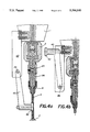
- FIGS. 4a and 4b each show the modes of execution of a tool-holder according to this invention, designed to hold a long, thin electrode (with a diameter of approximately 1 mm);
- FIG. 5 is a schematic representation of a mode of execution for the auxiliary tool, designed to manufacture and/or touch up a cylindrical electrode terminated by a hemisphere, a cone, or any other profile of revolution;
- FIGS. 6a and 6b and FIGS. 7a and 7b illustrate two possible variants of magazines suitable for standardised spherical electrodes and for the tool-holder in FIG. 3.
- EDM die sinking machines are fitted with components which enable the work table to move with respect to the tool along three orthogonal axes X, Y and Z, and the tool to rotate about its axis.
- these machines comprise a fast turning spindle capable of driving the tool at speeds of several thousand rpm, as described in patent pending CH 1128/89
- they are also capable of providing an EDM milling function, i.e. machining a large volume of material, possibly with a complex shape, using small electrodes which are normally of a simple shape.
- Some such machines can be equipped with a rotating spindle capable of pivoting the tool with respect to the vertical axis (as described in patent pending CH 1378/89). This increases the capabilities for the manufacture or touching up of standardised electrodes.
- the numerical control of the machine can, in particular, be connected to a CAD system used to define the shape of the recess to be milled, and to software defining the path to be followed by the tool-electrode.
- the column (10) actually comprises various systems which are not shown in the drawing (servo-mechanism operated by the numerical control, electronic stop, component as defined in patent pending CH 4142/88 preventing the head from moving up beyond a position in which the tool-electrode is no longer immersed in the machining fluid, for example), and which accurately monitor the vertical position of the machining head (1).
- Said numerical control also connected to two servo-actuators which control the table (5) and to an electrical pulse generator, is well known to persons skilled in art, as is the generator. These components are therefore not shown in the drawing, and are not described in the text that follows.
- Said numerical control system can include circuits which are programmed to record the position coordinates of the blank or tool-electrode (4).
- a working tank (20) is fixed to the table (5), and moves with the latter which is supported by the frame (19). This frame contains the tank for the dielectric liquid which constitutes the machining fluid, the filters, the pumps and any other components of the dielectric liquid supply and evacuation system; all these components are well known in the art and are therefore not shown.
- a work table (17), and parts (18) for setting the workpiece (7) to be machined, are fixed to the base of this tank (20).
- Said tank is equipped with various solenoid valves for filling, injection, suction or evacuation of the dielectric, as well as with thermostats, and devices enabling the dielectric level to be adjusted; all these components are of a known type, and none are shown.
- the auxiliary tool (6) is a chisel fitted at an angle to the axis of this chisel-holder (21), the oblique position being obtained through screw (23).
- the sphere (11) is not mounted on a separate column, as shown in FIG. 2B, but directly on said chisel-holder (21).
- the numerical control then orders the blank (4) to move down until it just touches the sphere (11) by electrical touch, at reference point "P", followed by a relative displacement along the three axes X, Y and Z in order to bring the tip of the chisel (6) into contact with the blank (4) at a point located at the height of the end of the required hemisphere (point A, FIG. 2a) or above this point, i.e. at a point located at a distance of at least "h” from the end of the blank (4) ("h” being equal to half of the diameter "d” of the blank electrode) (see FIG. 2a).
- the tip of the blank By modifying the program, it would be possible to shape the tip of the blank according to other profiles, such as a cone for example; however, the profile created can only be one with a symmetry of revolution around axis (C) of the blank electrode (which will subsequently be the rotation axis of the tool-electrode produced).
- a similar method is used to touch up a worn tool-electrode (4).
- the electrode (4) will obviously be shortened by a length Dx. This must be taken into account by the numerical control, so that machining can be resumed using an electrode tool whose active surface occupies a position which is identical to the original position prior to the touching up, and which has been stored in the memory of the numerical control system.
- the fastening of the tool-holder in the rotating spindle is achieved owing to an automatic locking system as described in patent CH 1128/89.
- the fastening component (25) is ended by a protruding section comprising a rectangular flare (29), whose dimensions (as measured in a plane perpendicular to the symmetry axis of the tool-holder) are slightly smaller than the dimensions of a slot cut in the end of a puller piston, fitted coaxially into the rotating spindle and operated from the top by a spring.
- this flare (29) is retained by the bottom of the puller piston. Fastening and unlocking of the tool-holder (3) from the rotating spindle can be carried out automatically.
- locking can be obtained by immobilizing the tool-holder in a rack opposite the slot in the puller piston. It is merely necessary to lower the machining head along the Z-axis, order the spindle to turn through a quarter of a turn, and then move it up again along the Z-axis.
- a pressurized fluid oil or compressed air, for example
- the machining current is conveyed to the tool-electrode (4) through the spindle (2) and the tool-holder (3), which explains the need for efficient cooling of the spindle/tool-holder assembly (see FIG. 3).
- Body units (26) with different diameters and profiles can be provided, in order to fasten parts (4) of different shapes and weights, without having to use a different fastening component (25).
- the fastening of a spherical blank or tool-electrode (4) into the body (26) is carried out very simply, so long as the sphere (4) is orientated with its groove (36) positioned horizontally the sphere (4) to be gripped is centered with respect to the tool-holder, and the dogs (35) of the spring grip (27) are brought into contact with the sphere (4).
- the dogs (35) fit into the groove (36) by simply pressing the sphere (4) home.
- a part used as a pusher can be coaxially introduced into the duct (32) in order to press out the electrode (4) and facilitate its dismounting.
- This pusher can be operated by any known means (electrical, pneumatic, hydraulic, mechanical), and should preferably be numerically controlled. It can be hollow and drilled with orifices at its bottom end, in order to connect injection chambers (30) and (33) together.
- FIG. 4 represents another type of tool-holder, for a device according to this invention, designed to support a long, thin electrode, either during manufacture in the case of a blank electrode, or during touching up in the case of a tool-electrode.
- "Fine” means electrodes shaped as solids of revolution with a diameter of approximately one millimeter.
- the tool-holder can be made up, as described above, by a fastening component (25) fixed to the rotating spindle, to hold its body (26).
- a fastening component (25) fixed to the rotating spindle, to hold its body (26).
- the other components in common with those of the tool-holder illustrated in FIG. 3 are referenced by the same numbers.
- FIG. 6 illustrates the first of these variants: a display unit (60) is secured by any known means (not shown) onto one of the walls of the working tank (20) (see FIG. 2), at approximately the same height as the clamping table (18); it therefore moves at the same time as the cross-slide table (5). It has four tronconical recesses (61a to 61d), with smaller diameters than those of the spheres 4a to 4d to be stored. The relative movements of the table (5) with respect to the machining head (1) will therefore enable the tool-holder (3) to be automatically brought near to the display unit (60), opposite the sphere to be grasped. The positions, i.e. the coordinates of the symmetry axes of these recesses (61), in other words the coordinates of the spheres (4) that they support, are stored in the numerical control working memory.
- a pulling up unit is provided at the end of the display unit (60). It consists of a fork with two horizontal teeth (62) and (63), between which the tool-holder (3) is able to slide; the distance between the horizontal teeth (62) and (63) is slightly greater than the tip of said tool-holder (3), which grips the spherical electrode (4), but slightly less than the diameter of said sphere (4).
- the operation of this unit is extremely simple: the elevation of the machining head is adjusted in such a way that the circular groove (36) of the sphere (4) is slightly above these teeth, and that the diameter (d) of this sphere is located below (see FIG. 6a).
- tube (74) Due to this configuration, only one sphere (4) is ever located above tube (74), which has an alternating movement. This is because tube (74) is actuated between the positions described in FIGS. 7a and 7b, which means that the forward movement brings a sphere (4) from chamber (72) to annular chamber (78). The sphere is held in suspension above funnel (75) ending said tube (74), by a cushion of air (80) created by the pressurized air ejected by a circular orifice (76) connected to the injection chamber (77). This air bearing enables the sphere to be supported without friction.
- the device defined by this invention it is therefore possible to mill a recess of any size and profile (provided that it can be broken down into a combination of simple volumes), with an accuracy that can be even greater than that obtained by standard die sinking.
- Today it is possible to describe a complex shape as a series of simple elementary shapes, using known CAD (Computer Aided Design) systems.
- the profile of these simple volumes can be sent to the numerical control of the EDM machine, and stored in its working memory in order to touch up or even turn the corresponding elementary electrodes corresponding to the simple volumes required. By working in this "self-sufficient" manner, the EDM milling machine could become a true "intelligent" machine.
Landscapes
- Engineering & Computer Science (AREA)
- Mechanical Engineering (AREA)
- Manufacturing & Machinery (AREA)
- Electrical Discharge Machining, Electrochemical Machining, And Combined Machining (AREA)
- Manufacture And Refinement Of Metals (AREA)
- Forging (AREA)
Applications Claiming Priority (3)
| Application Number | Priority Date | Filing Date | Title |
|---|---|---|---|
| CH2622/89 | 1989-07-13 | ||
| CH262289 | 1989-07-13 | ||
| PCT/CH1990/000163 WO1991000791A1 (fr) | 1989-07-13 | 1990-07-05 | Dispositif, ebauches standard et electrodes normalisees pour fraisage par electroerosion |
Publications (1)
| Publication Number | Publication Date |
|---|---|
| US5396040A true US5396040A (en) | 1995-03-07 |
Family
ID=4237900
Family Applications (1)
| Application Number | Title | Priority Date | Filing Date |
|---|---|---|---|
| US07/675,903 Expired - Lifetime US5396040A (en) | 1989-07-13 | 1990-07-05 | Device, standard blanks and standardized electrodes for electro-discharge milling |
Country Status (8)
| Country | Link |
|---|---|
| US (1) | US5396040A (de) |
| EP (1) | EP0444160B1 (de) |
| AT (1) | ATE136482T1 (de) |
| DE (1) | DE69026493T2 (de) |
| DK (1) | DK0444160T3 (de) |
| ES (1) | ES2086406T3 (de) |
| RU (1) | RU2044610C1 (de) |
| WO (1) | WO1991000791A1 (de) |
Cited By (12)
| Publication number | Priority date | Publication date | Assignee | Title |
|---|---|---|---|---|
| US6261153B1 (en) | 1960-12-15 | 2001-07-17 | Hayes Lemmerz International, Inc. | Apparatus and method of machining brake components |
| US6403910B1 (en) * | 1999-12-14 | 2002-06-11 | Hi-Tek Manufacturing, Inc. | EDM apparatus and method for performing EDM operation |
| US6505716B1 (en) | 1999-11-05 | 2003-01-14 | Hayes Lemmerz International, Inc. | Damped disc brake rotor |
| US20030093175A1 (en) * | 2001-11-14 | 2003-05-15 | Industrial Technology Research Institute | Multiple discharge-servo curve control method and device of electrical discharge machine |
| US6566623B2 (en) * | 2001-05-30 | 2003-05-20 | Harvest Precision Components, Inc. | Method and apparatus for electric discharge machining with a dressing tool |
| US20040168288A1 (en) * | 2003-02-28 | 2004-09-02 | Mustafizur Rahman | Compound fabrication process and apparatus |
| US20070084833A1 (en) * | 2004-05-18 | 2007-04-19 | Alexander Xidacis | Method and apparatus for electrode dressing |
| US20070151954A1 (en) * | 2006-01-05 | 2007-07-05 | General Electric Company | Methods and apparatus for fabricating components |
| CN102922063A (zh) * | 2012-10-26 | 2013-02-13 | 江苏技术师范学院 | 电火花铣削装置及方法 |
| US20130139660A1 (en) * | 2005-12-13 | 2013-06-06 | Renishaw Plc | Method of Machine Tool Calibration |
| US9849530B2 (en) * | 2014-07-30 | 2017-12-26 | Mitsubishi Electric Corporation | Electric discharge machining method and electric discharge machine |
| US20200030901A1 (en) * | 2015-06-12 | 2020-01-30 | Makino Milling Machine Co., Ltd. | Small-hole electric discharge machining machine |
Families Citing this family (4)
| Publication number | Priority date | Publication date | Assignee | Title |
|---|---|---|---|---|
| EP0555818B1 (de) | 1992-02-12 | 1995-12-13 | Charmilles Technologies S.A. | Verfahren und Vorrichtung zum elektroerosiven Herstellen hohler 3-D-Kontouren mit einer dünnen rotierenden Elektrode |
| DE10033515A1 (de) * | 2000-07-11 | 2002-01-24 | Mecatool Ag Flawil | Elektrode für Elektroentladungbearbeitung |
| RU2221676C2 (ru) * | 2001-08-27 | 2004-01-20 | ОАО "НПО Энергомаш им. акад. В.П. Глушко" | Способ электроэрозионной обработки ротора (или соплового блока) турбины и приспособление для осуществления способа |
| CN109570666B (zh) * | 2018-11-05 | 2020-11-06 | 南京航空航天大学 | 电解线切割加工用双极性工具电极及制作与加工方法 |
Citations (10)
| Publication number | Priority date | Publication date | Assignee | Title |
|---|---|---|---|---|
| US3122628A (en) * | 1963-01-31 | 1964-02-25 | Inone Kiyoshi | Electrical discharge grinding apparatus with automatic electrode reshaping provision |
| US3398253A (en) * | 1965-10-19 | 1968-08-20 | F Jos Lamb Company Inc | Grinding machine with electric discharge machining mechanism for reshaping crush roll |
| US4754115A (en) * | 1985-03-19 | 1988-06-28 | Extrude Hone Corporation | High speed electrical discharge machining by redressing high resolution graphite electrodes |
| US4764653A (en) * | 1985-09-16 | 1988-08-16 | Ag Fur Industrielle Elektronik Agie Losone Bei Locarno | Process and apparatus employing electroerosion |
| US4827213A (en) * | 1987-03-18 | 1989-05-02 | Daimler-Benz Aktiengesellschaft | Apparatus for the contactless determination of variable intervals of distance by pulsatory spark discharges |
| US4859824A (en) * | 1986-10-03 | 1989-08-22 | Asahi Kogaku Kogyo Kabushiki Kaisha | Electrospark machine system, assembly for use with system, device for mounting electrospark machining electrode, and method of shaping a workpiece |
| US4891485A (en) * | 1987-06-10 | 1990-01-02 | Charmilles Technologies S.A. | Device for fastening an EDM tool in plural orientations |
| US5038012A (en) * | 1988-08-30 | 1991-08-06 | Herbert Walter Werkzeung- Und Maschinenbau | Electrical discharge process and machining apparatus |
| US5049715A (en) * | 1989-02-03 | 1991-09-17 | Mitsubishi Denki Kabushiki Kaisha | Electric discharge machine |
| US5091622A (en) * | 1989-05-10 | 1992-02-25 | Mitsubishi Denki K.K. | Compound machining method and apparatus |
Family Cites Families (1)
| Publication number | Priority date | Publication date | Assignee | Title |
|---|---|---|---|---|
| JPS59169720A (ja) * | 1983-03-16 | 1984-09-25 | Inoue Japax Res Inc | 電気加工用マシニングセンタ |
-
1990
- 1990-07-05 ES ES90909615T patent/ES2086406T3/es not_active Expired - Lifetime
- 1990-07-05 DK DK90909615.8T patent/DK0444160T3/da active
- 1990-07-05 DE DE69026493T patent/DE69026493T2/de not_active Expired - Fee Related
- 1990-07-05 WO PCT/CH1990/000163 patent/WO1991000791A1/fr not_active Ceased
- 1990-07-05 AT AT90909615T patent/ATE136482T1/de not_active IP Right Cessation
- 1990-07-05 EP EP90909615A patent/EP0444160B1/de not_active Expired - Lifetime
- 1990-07-05 US US07/675,903 patent/US5396040A/en not_active Expired - Lifetime
-
1991
- 1991-03-13 RU SU914895317A patent/RU2044610C1/ru not_active IP Right Cessation
Patent Citations (10)
| Publication number | Priority date | Publication date | Assignee | Title |
|---|---|---|---|---|
| US3122628A (en) * | 1963-01-31 | 1964-02-25 | Inone Kiyoshi | Electrical discharge grinding apparatus with automatic electrode reshaping provision |
| US3398253A (en) * | 1965-10-19 | 1968-08-20 | F Jos Lamb Company Inc | Grinding machine with electric discharge machining mechanism for reshaping crush roll |
| US4754115A (en) * | 1985-03-19 | 1988-06-28 | Extrude Hone Corporation | High speed electrical discharge machining by redressing high resolution graphite electrodes |
| US4764653A (en) * | 1985-09-16 | 1988-08-16 | Ag Fur Industrielle Elektronik Agie Losone Bei Locarno | Process and apparatus employing electroerosion |
| US4859824A (en) * | 1986-10-03 | 1989-08-22 | Asahi Kogaku Kogyo Kabushiki Kaisha | Electrospark machine system, assembly for use with system, device for mounting electrospark machining electrode, and method of shaping a workpiece |
| US4827213A (en) * | 1987-03-18 | 1989-05-02 | Daimler-Benz Aktiengesellschaft | Apparatus for the contactless determination of variable intervals of distance by pulsatory spark discharges |
| US4891485A (en) * | 1987-06-10 | 1990-01-02 | Charmilles Technologies S.A. | Device for fastening an EDM tool in plural orientations |
| US5038012A (en) * | 1988-08-30 | 1991-08-06 | Herbert Walter Werkzeung- Und Maschinenbau | Electrical discharge process and machining apparatus |
| US5049715A (en) * | 1989-02-03 | 1991-09-17 | Mitsubishi Denki Kabushiki Kaisha | Electric discharge machine |
| US5091622A (en) * | 1989-05-10 | 1992-02-25 | Mitsubishi Denki K.K. | Compound machining method and apparatus |
Cited By (18)
| Publication number | Priority date | Publication date | Assignee | Title |
|---|---|---|---|---|
| US6261153B1 (en) | 1960-12-15 | 2001-07-17 | Hayes Lemmerz International, Inc. | Apparatus and method of machining brake components |
| US6296549B1 (en) | 1998-04-22 | 2001-10-02 | Hayes Lemmerz International, Inc. | Apparatus and method of machining brake components |
| US6505716B1 (en) | 1999-11-05 | 2003-01-14 | Hayes Lemmerz International, Inc. | Damped disc brake rotor |
| US6403910B1 (en) * | 1999-12-14 | 2002-06-11 | Hi-Tek Manufacturing, Inc. | EDM apparatus and method for performing EDM operation |
| US6566623B2 (en) * | 2001-05-30 | 2003-05-20 | Harvest Precision Components, Inc. | Method and apparatus for electric discharge machining with a dressing tool |
| US6941187B2 (en) * | 2001-11-14 | 2005-09-06 | Industrial Technology Research Institute | Multiple discharge-servo curve control method and device for an electrical discharge machine |
| US20030093175A1 (en) * | 2001-11-14 | 2003-05-15 | Industrial Technology Research Institute | Multiple discharge-servo curve control method and device of electrical discharge machine |
| US20040168288A1 (en) * | 2003-02-28 | 2004-09-02 | Mustafizur Rahman | Compound fabrication process and apparatus |
| US6935003B2 (en) * | 2003-02-28 | 2005-08-30 | National University Of Singapore | Compound fabrication process and apparatus |
| SG124280A1 (en) * | 2003-02-28 | 2006-08-30 | Univ Singapore | Compound fabrication process and apparatus |
| US20070084833A1 (en) * | 2004-05-18 | 2007-04-19 | Alexander Xidacis | Method and apparatus for electrode dressing |
| US7923657B2 (en) * | 2004-05-18 | 2011-04-12 | Rolls-Royce Plc | Method and apparatus for electrode dressing |
| US20130139660A1 (en) * | 2005-12-13 | 2013-06-06 | Renishaw Plc | Method of Machine Tool Calibration |
| US8875603B2 (en) * | 2005-12-13 | 2014-11-04 | Renishaw Plc | Method of machine tool calibration |
| US20070151954A1 (en) * | 2006-01-05 | 2007-07-05 | General Electric Company | Methods and apparatus for fabricating components |
| CN102922063A (zh) * | 2012-10-26 | 2013-02-13 | 江苏技术师范学院 | 电火花铣削装置及方法 |
| US9849530B2 (en) * | 2014-07-30 | 2017-12-26 | Mitsubishi Electric Corporation | Electric discharge machining method and electric discharge machine |
| US20200030901A1 (en) * | 2015-06-12 | 2020-01-30 | Makino Milling Machine Co., Ltd. | Small-hole electric discharge machining machine |
Also Published As
| Publication number | Publication date |
|---|---|
| ATE136482T1 (de) | 1996-04-15 |
| WO1991000791A1 (fr) | 1991-01-24 |
| ES2086406T3 (es) | 1996-07-01 |
| EP0444160B1 (de) | 1996-04-10 |
| EP0444160A1 (de) | 1991-09-04 |
| DE69026493D1 (de) | 1996-05-15 |
| RU2044610C1 (ru) | 1995-09-27 |
| DE69026493T2 (de) | 1996-11-28 |
| DK0444160T3 (da) | 1996-08-05 |
Similar Documents
| Publication | Publication Date | Title |
|---|---|---|
| US5396040A (en) | Device, standard blanks and standardized electrodes for electro-discharge milling | |
| US6935003B2 (en) | Compound fabrication process and apparatus | |
| US5420388A (en) | Tool-holder and rapid rotary spindle | |
| CN201300271Y (zh) | 多轴联动聚晶金刚石刀具电火花磨削加工机 | |
| JPH01115534A (ja) | 複合加工機 | |
| CN109623624B (zh) | 一种薄壁套筒类零件的珩磨加工工艺 | |
| US4439660A (en) | Electroerosive contour-machining method and apparatus with a rotary tool electrode | |
| US6369343B1 (en) | Method and apparatus for electrical discharge machining | |
| JPH11165211A (ja) | 内面加工機 | |
| US5038012A (en) | Electrical discharge process and machining apparatus | |
| KR100601208B1 (ko) | 방전 가공 장치 | |
| US4725704A (en) | Travelling wire and cavity sinking EDM apparatus | |
| CN117300406A (zh) | 一种双激光头打孔装置及方法 | |
| KR920009122B1 (ko) | 상이한 방향으로 공구를 고정시키는 장치 | |
| CN216729942U (zh) | 能调节电极直径的多头电火花机床 | |
| US3783225A (en) | Production of conical bores | |
| US4638141A (en) | Modular EDM system | |
| CA2015469C (en) | Method and apparatus for non-contact machining with dynamic feedback control | |
| JPH11267925A (ja) | 回転切削工具のワイヤカット方法および装置 | |
| JP3130748B2 (ja) | 彫刻用工具及びそのための装置 | |
| CN109465973A (zh) | 一种罗拉开槽定位工装 | |
| JPH0565291B2 (de) | ||
| JPH09136222A (ja) | 電極ガイド自動交換装置を備えた放電加工機 | |
| JPH0724170Y2 (ja) | 細穴放電加工機の電極案内 | |
| CN222176046U (zh) | 圆形件侧向孔钻孔辅助装置 |
Legal Events
| Date | Code | Title | Description |
|---|---|---|---|
| AS | Assignment |
Owner name: CHARMILLES TECHNOLOGIES S.A. Free format text: ASSIGNMENT OF ASSIGNORS INTEREST.;ASSIGNOR:GIRARDIN, ROGER;REEL/FRAME:006070/0859 Effective date: 19910513 |
|
| STCF | Information on status: patent grant |
Free format text: PATENTED CASE |
|
| CC | Certificate of correction | ||
| FEPP | Fee payment procedure |
Free format text: PAYOR NUMBER ASSIGNED (ORIGINAL EVENT CODE: ASPN); ENTITY STATUS OF PATENT OWNER: LARGE ENTITY |
|
| FPAY | Fee payment |
Year of fee payment: 4 |
|
| FPAY | Fee payment |
Year of fee payment: 8 |
|
| FPAY | Fee payment |
Year of fee payment: 12 |