US5417543A - Process and apparatus for handling blank stacks - Google Patents
Process and apparatus for handling blank stacks Download PDFInfo
- Publication number
- US5417543A US5417543A US08/087,252 US8725293A US5417543A US 5417543 A US5417543 A US 5417543A US 8725293 A US8725293 A US 8725293A US 5417543 A US5417543 A US 5417543A
- Authority
- US
- United States
- Prior art keywords
- stack
- blank
- base
- stacks
- blanks
- Prior art date
- Legal status (The legal status is an assumption and is not a legal conclusion. Google has not performed a legal analysis and makes no representation as to the accuracy of the status listed.)
- Expired - Lifetime
Links
Images


Classifications
-
- B—PERFORMING OPERATIONS; TRANSPORTING
- B65—CONVEYING; PACKING; STORING; HANDLING THIN OR FILAMENTARY MATERIAL
- B65G—TRANSPORT OR STORAGE DEVICES, e.g. CONVEYORS FOR LOADING OR TIPPING, SHOP CONVEYOR SYSTEMS OR PNEUMATIC TUBE CONVEYORS
- B65G57/00—Stacking of articles
- B65G57/005—Stacking of articles by using insertions or spacers between the stacked layers
-
- B—PERFORMING OPERATIONS; TRANSPORTING
- B65—CONVEYING; PACKING; STORING; HANDLING THIN OR FILAMENTARY MATERIAL
- B65B—MACHINES, APPARATUS OR DEVICES FOR, OR METHODS OF, PACKAGING ARTICLES OR MATERIALS; UNPACKING
- B65B19/00—Packaging rod-shaped or tubular articles susceptible to damage by abrasion or pressure, e.g. cigarettes, cigars, macaroni, spaghetti, drinking straws or welding electrodes
- B65B19/02—Packaging cigarettes
- B65B19/22—Wrapping the cigarettes; Packaging the cigarettes in containers formed by folding wrapping material around formers
- B65B19/228—Preparing and feeding blanks
-
- Y—GENERAL TAGGING OF NEW TECHNOLOGICAL DEVELOPMENTS; GENERAL TAGGING OF CROSS-SECTIONAL TECHNOLOGIES SPANNING OVER SEVERAL SECTIONS OF THE IPC; TECHNICAL SUBJECTS COVERED BY FORMER USPC CROSS-REFERENCE ART COLLECTIONS [XRACs] AND DIGESTS
- Y10—TECHNICAL SUBJECTS COVERED BY FORMER USPC
- Y10S—TECHNICAL SUBJECTS COVERED BY FORMER USPC CROSS-REFERENCE ART COLLECTIONS [XRACs] AND DIGESTS
- Y10S414/00—Material or article handling
- Y10S414/10—Associated with forming or dispersing groups of intersupporting articles, e.g. stacking patterns
- Y10S414/12—Associated with forming or dispersing groups of intersupporting articles, e.g. stacking patterns including means pressing against top or end of group
Definitions
- the invention relates to a process for handling stacks of blanks (blank stacks), especially in conjunction with a packaging machine, in which the blank stacks rest on a base and are removed from this base in order to be processed in the pack aging machine. Additionally, the invention relates to an apparatus for carrying out this process.
- Cigarette packs of the hinge-lid type are formed from blanks of thin cardboard. These blanks are delivered by the manufacturer in the form of blank stacks, for example on a pallet.
- the invention is directed to the problem of automatically and mechanically handling the blank stacks without any involvement of manual work.
- the blank stacks must be removed from the base (pallet) and introduced into the packaging process.
- Known in the art are apparatus which have one or more stack holders for grasping and holding one blank stack each.
- the stack holders are formed from a clamping tongue resting on the underside of the blank stack, and a counter pressure means acting upon tile top side (DE-A-37 18 601).
- the problem with such apparatus is to move the clamping tongue underneath the blank stack which rests on a base.
- the blank stack is deformed by a pressure piece acting upon the top side, such that a gap is formed underneath the stack on the side assigned to the clamping tongue, and the clamping tongue is introduced into this gap.
- the process according to the invention is characterized in that the blank stack is lifted off the base, and in that the few lowermost blanks of the blank stack which are not grasped are lifted up as well by an air jet which is directed from above onto the base next to the stack.
- the invention is based on the finding that, especially when a blank stack is lifted by means which act upon side faces of the blank stack, lowermost blanks are not grasped.
- an air jet is directed according to the invention from above onto the base next to the blank stack. Surprisingly, this air jet lifts the lowermost blanks off the base and moves them up to the blank stack.
- the apparatus comprises at least one stack lifter for lifting the stack off the base, and at least one air nozzle by means of which a downwardly directed air jet is directed against the base.
- the complete apparatus is designed such that the blank stack which is fully lifted by the stack lifter and an air blast is grasped and discharged by a stack holder which grasps the stack at the top side and underside by appropriate holding means.
- the apparatus is formed from several side-by-side units, each for grasping one blank stack, so that, for example, four blank stacks can be lifted and discharged simultaneously.
- a lifting head designed in this manner may, for example, be disposed on a robot, in particular on the articulated arm of the robot.
- the lifting head can also be used for removing separator sheets which separate layers of the blank stack which are arranged on top of one another.
- these separator sheets which may for example be formed from paper, are grasped at an edge by the lifting head and are removed without any friction by way of rolling off or being pulled off the blank stacks located thereunder.
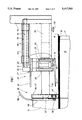
- FIG. 1 is a side view, partly shown in vertical section, of a portion of a lifting head
- FIG. 2 is a plan view of a lifting head
- FIG. 3 to FIG. 5 show side views of a portion of a lifting head during the process of grasping a blank stack
- FIG. 6 shows a detail of a lifting head, in particular a vertical section of clamping jaws
- FIG. 7 shows a further detail, in particular another vertical section of a clamping jaw in the lower region of the jaw
- FIG. 8 shows a pallet with blank stacks during the removal of a separator sheet.
- the exemplary embodiment illustrated in the drawings is directed to the handling of blanks 10 of thin cardboard.
- these are blanks for cigarette packs of the hinge-lid type.
- the blanks 10 and the packs formed therefrom have an almost identical shape all over the world.
- a characteristic feature of these blanks is a central projection 11 which is located in the region of a head end and serves for forming a lid of the pack.
- This projection has a significantly smaller width than the rest of the blank 10.
- the projection 11 serves for forming an inner lid tab which rests on the inner side of a front wall of the lid after being folded.
- the projection 11 is adjoined by an inclined edge 12 on both sides of the blank.
- This inclined edge 12 also corresponds to the conventional design of a blank 10 for this pack type.
- the edge 12 forms the lower delimitation of an outer side wall of the lid.
- the blanks 10 are delivered in the form of stacks, in particular blank stacks 13, in order to be processed, especially in packaging machine (not shown).
- the blank stack is formed from approximately 500 blanks 10.
- blank stacks 13 are provided on one base.
- the blank stacks 13 rest on a pallet 14.
- Several layers of such blank stacks 13 are arranged on top of one another in the form of stack layers 15.
- the individual stack layers 15 are separated from one another by separator sheets 16 formed from a thin flexible blank, especially from a blank made of paper.
- separator sheets 16 formed from a thin flexible blank, especially from a blank made of paper.
- the blank stacks 13 are disposed in rows of side-by-side blank stacks 13. The configuration is such that the longitudinal axes of the elongated blanks extend parallel to one another.
- Each projection 11 is located on a free side of the stack layer 15.
- the blank stacks 13 are removed from the pallet 14 in layers and are introduced into the packaging process of the packaging machine.
- a handling device is used, especially a customary robot with a cantilever arm and a lifting head 18 attached thereto.
- the lifting head 18 is connected to the cantilever arm of the robot or another device by a central supporting rod 19.
- the lifting head 18 is designed for a simultaneous lifting of several blank stacks 13. In the present case, four side-by-side blank stacks 13 are picked up and discharged.
- the blank stacks 13 may be deposited by the lifting head 18 on a transporting means, for example a conveyor belt.
- each stack holder 20 is provided with means for grasping a blank stack 13 at opposite sides, in particular at the underside and the top side.
- a clamping tongue 21 contacts the blank stack 13 at the underside.
- a pressure plate 22 acts as a counter pressure means. Clamping tongue 21 and pressure plate 22 can be moved relative to one another.
- the lower clamping tongue 21 is movable up and down by a pressure medium cylinder 23.
- the clamping tongue 21 is disposed on a carrier piece 24 and projects therefrom unilaterally.
- the carrier piece is connected with a piston rod 25 of the upright pressure medium cylinder 23.
- Guide pins 26 are attached to the carrier piece 24 and slide up and down in bores of a supporting frame 27 when the clamping tongue 21 moves.
- the lifting head 18 is provided with separate means for lifting the blank stack 13, such that the stack holder 20 can move into the receiving position for grasping the blank stack 13, i.e. with the clamping tongue 21 underneath the blank stack 13.
- Each stack holder 20 is associated with a stack lifter 28. This stack lifter is used before a blank stack 13 is grasped by the stack holder 20. For this purpose, the stack lifter 28 projects beyond the stack holder 20 in the initial position (FIGS. 1 and 2).
- the stack lifters 28 reach the working position first. They grasp and then lift the associated blank stack 13. Thereafter, the stack holders 20 are moved relative to the stack lifters 28 in the direction of the blank stacks 13 until the clamping tongue 21 and the pressure plate 22 are located in position above and below the blank stack 13.
- the stack holders 20 are movable as a whole relative to the stack lifters 28. All stack holders 20 of the lifting head 18 are attached to a horizontal crosspiece 29 in the form of a flat section, in particular underneath this crosspiece.
- the supporting frames 27 for the clamping tongues 21 are located on the underside of the crosspiece 29.
- the pressure plates 22 take the form of comb-like projections of the crosspiece 29.
- the crosspiece 29 is connected to an intermediate piece 30 formed from a rectangular section.
- This intermediate piece is located centrally on the crosspiece 29 and is connected to a piston rod 31 of a horizontal pressure medium cylinder 32 which acts as an actuating means for the stack holders 20.
- the pressure medium cylinder is located on a frame-like supporting device 33 of the lifting head 18. Additionally, the crosspiece 29 is guided accurately with guide rods 34 in bores of a guide 35 of the supporting device 33.
- the piston rod 31 is extended and retracted, the stack holders 20 are shift ed in the direction toward the blank stacks 13 which are to be taken up or back into the initial position of FIGS. 1 and 2.
- the stack lifters 28 are designed in a special way. They take the form of clamping tools which laterally grasp and lift each blank stack 13. In the present exemplary embodiment, the specific shape of the blanks 10 is utilized for grasping the stacks.
- Each stack lifter 28 is equipped with two upright clamping jaws 36, 37.
- the clamping jaws are disposed on the ends of horizontal actuating arms 38, 39.
- these arms consist of a flat section, especially a flat section made of spring steel.
- the actuating arms 38, 39 are elastic ally deformable like leaf springs, i.e. they are pivotable horizontally.
- each actuating arm 38, 39 is associated with an actuating means, especially a pressure medium cylinder 40 with an extendable piston rod which takes the form of a short-stroke cylinder. The piston rod of this cylinder directly contacts the actuating arm 38, 39.
- the pressure medium cylinders 40 are disposed on the free ends of horizontally directed supporting struts 60 of the lifting head 18. These supporting struts 60 take the form of flat sections and a 1 so serve for fixing the actuating arms 38, 39 with a bent free end.
- the upright clamping jaws 36, 37 are disposed at the ends of the actuating arms 38, 39 and contact the blank stacks 13 in the region of the projection 11 of the blanks 10, that is to say of the blank stacks 13.
- the narrow clamping jaws 36, 37 have an elastic contact surface 41 which contacts the blank stack 13.
- recesses 42 are formed in the region of head ends of the blank stacks 13, which recesses are defined by the projections 11 and the edges 12.
- the clamping jaws 36, 37 of the adjacent stack lifters 28 enter these recesses 42 by means of an appropriate advance of the lifting head 18. In the position of FIG. 2, the clamping jaws 36, 37 can be subjected to clamping force, such that they contact and clamp the projections 11 of the blank stack 13.
- FIGS. 3 to 5 After the blank stacks 13 have been grasped by the stack lifters 28, they are lifted to a position shown in FIGS. 3 to 5. This lifting movement can be conducted by way of lifting the entire lifting head 18. Because the blanks 10 or blank stacks 13 are grasped only at a head end (projections 11), a portion of the blank stacks 13 is lifted which faces the stack lifters 28. However, the partially lifted position of the blank stacks 13 is sufficient to move the stack holders 20 into position. The sequence of movements is illustrated in FIGS. 3 to 5. Once the blank stacks 13 are in the lifted position (FIG. 3), the clamping tongue 21 is downwardly extended (FIG. 4). As a result, the clamping tongue is located in a plane below the (lifted) blank stack 13.
- all stack holders 20 are moved together in the direction toward the blank stacks 13 until the clamping tongue 21 and the pressure plate 22 reach the receiving position below and above the blank stack 13. Subsequently, the clamping tongue 21 is moved upwards, so that the blank stack 13 is grasped in a clamping fashion in the region of the head end. Now, the lifting head 18 can be lifted as a whole together with the blank stacks 13 and can be moved to the position in which the blank stacks 13 are deposited.
- the specific contour of the blanks 10 in the head region i.e. the narrow projection 11 and the adjoining inclined edges 12 facilitate the positioning of the clamping jaws 36, 37 of the stack lifter 28.
- the (open) clamping jaws 36, 37 are moved up to the blank stacks 13 in the region of the inclined surfaces formed from the edges 12 and then slide along these surfaces when the clamping jaws 36, 37 are closed.
- the inclined surfaces thus effect a guidance of the clamping jaws 36, 37 during the closing process.
- the stack lifters 28 and their clamping jaws 36, 37 are designed in a special way.
- Optoelectric sensors 44, 45 are disposed in a cavity 43 of the clamping jaws 36, 37--in the present case a bore which passes into the clamping jaws from the top side. These sensors are connected to an electronic interpreting means via lines 46. The sensors 44, 45 create a light barrier 47. This monitoring device determines for each stack lifter 28 whether a blank stack 13 is present in the region of the respective stack lifter 28 and is located in a proper position.
- At least the two outer clamping jaws 36, 37 of the lifting head 18 are provided with a further sensing means.
- This sensing means is a sensing slide 48 which is disposed on the underside of the clamping jaws 36, 37.
- the sensing slide forms the lower portion of the clamping jaw 36, 37 which means it is part of the clamping jaw.
- the sensing slide 48 is mounted displaceably with a pin 49 in an upright bore 50 of the clamping jaw 36, 37, in particular against the pressure of asp ring 51 located in the bore 50.
- a transversely directed locking pin 52 inhibits rotational movements of the sensing slide 48 and prevents it from falling out of the bore 50.
- the sensing slide 48 is provided to ensure that the clamping jaws 36, 37 correctly rest on the base, especially on the separator sheet 16, in the position for lifting a blank stack 13.
- the stack lifters 28 are moved toward the blank stacks 13 and are, first of all, lowered when they are in the clamping position until the sensing slide 48 contacts the lower end of the remaining portion of the clamping jaw 36, 37, thereby pressing together the spring 51.
- a signal is generated which initiates the clamping process.
- so-called proximity switches 53, 54 are used as signal transmitters. As a safety precaution, two of these proximity switches are arranged on top of one another in this case.
- the proximity switches 53, 54 are triggered by the pin 49 of the sensing slide 48 during its upward movement.
- the actual outstanding feature of the apparatus is the measure provided for accurately receiving and accurately lifting up the blank stack 13 with all blanks 10.
- the clamping jaws 36, 37 are not suitable for reliably taking up the entire blank stack 13.
- lower blanks 10 for example the two, three or four lowermost blanks 10 are not grasped.
- these lowermost blanks must also be picked up by the stack holder 20.
- the stack lifters 28 are associated with separate lifting means which ensure an upward movement, that is to say a lifting of the lower blanks 10 which are not grasped by the clamping jaws 36, 37.
- an air jet is directed onto the base from above, in particular onto the respective uppermost separator sheet 16. The air jet hits the separator sheet 16 next to the blank stacks 13, in particular in a region immediately adjacent to the clamping jaws 36, 37.
- the vertically or nearly vertically directed compressed air jet lifts the lower free blanks 10 from the base (separator sheet 16), such that these blanks are up to the underside of the lifted blank stack 13 at least in the region of the projection 18.
- the means of the stack holder 20 can grasp the entire blank stack 13 at the underside.
- the compressed air jet is generated by upright air nozzles 55.
- These are upright pipe pieces 56 which are connected to the adjacent clamping jaw 36, 37 by a connecting piece 57.
- the pipe piece 56 or air nozzle 55 is connected to a (central) compressed air source via a tube line 58.
- the air nozzles 55 are disposed in the region of the recesses 42, i.e. laterally next to the blanks 10. It is important for an effective operation of the air nozzles 55 and the air jet that such an air jet takes effect on both sides of each blank stack 13. In the present example, only one air nozzle 55 is located in the recesses 42 between adjacent blank stacks 13, and thus acts upon both adjacent blank stacks 13.
- the compressed be air can directed onto the base through the air nozzles 55 with a pressure of 5 to 7 bar.
- the distance between the air nozzles 55 and the base (separator sheet 16) is approximately 5 to 10 mm in the illustrated exemplary embodiment.
- the inner diameter of the air nozzle 55 and the pipe piece 56 is approximately 4 mm.
- the mode of operation of the stack lifter 28 which is constructed in this manner is of prime importance for the operativeness of the apparatus.
- the blanks 10 are designed with a portion having a reduced width, so that the clamping means of the stack lifter 28 can clamp the blanks from the sides.
- the effect of the air nozzles 55, that is to say of the (nearly) vertical air jet permits a complete take-up of the blank stacks 13 without any risk of damaging the lower blanks by mechanical means.
- the apparatus is provided with another outstanding feature.
- a separator sheet 16 rests freely on the following stack layer 15. The separator sheet 16 has to be removed without shifting the blanks of the stack layer 15 located thereunder.
- the lifting head 18 is provided with means for grasping the upper free separator sheet 16. These are suction means 59 which grasp the separator sheet 16 at the top side by means of negative pressure.
- the suction means--in the present exemplary embodiment two suction means--are disposed on the lifting head 18, in particular on the supporting device 33 thereof.
- the suction means 59 are located in a region which is situated away from the stack holder 20 and the stack lifter 28 and faces the rearward part of the lifting head 18, in particular on the sides, i.e. spaced apart at a great distance. After a stack layer 15 has been removed, the lifting head 18 moves across the pallet 14 until the suction means 59 grasp the separator sheet 16 in a marginal region.
- the lifting head 18 is now lifted and tilted simultaneously and, as a result, the separator sheet 16 is lifted on one side and is gradually lifted off the following stack layer 16 in a rolling movement, as it is evident from FIG. 8. Accordingly, no transversely directed (frictional) forces are exerted on the blanks 10 of the following stack layer 16.
- this method of removing a separator sheet 16 may also be used independent of the specific design of the means for transporting the blank stacks 13.
Landscapes
- Engineering & Computer Science (AREA)
- Mechanical Engineering (AREA)
- Sheets, Magazines, And Separation Thereof (AREA)
- Manipulator (AREA)
- De-Stacking Of Articles (AREA)
Applications Claiming Priority (2)
| Application Number | Priority Date | Filing Date | Title |
|---|---|---|---|
| DE4222609.0 | 1992-07-10 | ||
| DE4222609A DE4222609A1 (de) | 1992-07-10 | 1992-07-10 | Verfahren und Vorrichtung zum Handhaben von Zuschnitt-Stapeln |
Publications (1)
| Publication Number | Publication Date |
|---|---|
| US5417543A true US5417543A (en) | 1995-05-23 |
Family
ID=6462867
Family Applications (1)
| Application Number | Title | Priority Date | Filing Date |
|---|---|---|---|
| US08/087,252 Expired - Lifetime US5417543A (en) | 1992-07-10 | 1993-07-08 | Process and apparatus for handling blank stacks |
Country Status (5)
| Country | Link |
|---|---|
| US (1) | US5417543A (de) |
| EP (1) | EP0579031B1 (de) |
| JP (1) | JP3025396B2 (de) |
| BR (1) | BR9302823A (de) |
| DE (2) | DE4222609A1 (de) |
Cited By (19)
| Publication number | Priority date | Publication date | Assignee | Title |
|---|---|---|---|---|
| US5642980A (en) * | 1995-04-28 | 1997-07-01 | G.D. S.P.A. | Device for picking up stacks of products from a support |
| US5709524A (en) * | 1995-06-22 | 1998-01-20 | G.D. S.P.A. | Device for picking up stacks of products from a support |
| US5820334A (en) * | 1995-06-07 | 1998-10-13 | Standard Duplicating Machines Corporation | Paper set feeding |
| US6074163A (en) * | 1997-08-27 | 2000-06-13 | Matsushita Electric Industrial Co., Ltd. | Apparatus for taking away plate and method for taking away plate |
| US6126384A (en) * | 1995-06-07 | 2000-10-03 | Standard Duplicating Machines Corporation | Paper set feeding |
| US6266316B1 (en) * | 1999-03-01 | 2001-07-24 | Hewlett-Packard Company | Automatic splaying picker finger |
| US6379106B1 (en) * | 1999-04-15 | 2002-04-30 | Oma S.R.L. | Depalletizing machine |
| US20020090290A1 (en) * | 2000-12-22 | 2002-07-11 | G.D Societa' Per Azioni | Method and unit for transferring blanks |
| US20040186616A1 (en) * | 2000-10-23 | 2004-09-23 | Bowe Bell + Howell Postal Systems Company | Flats bundle collator |
| US20050042319A1 (en) * | 2002-07-22 | 2005-02-24 | Maschinenfabrik J. Dieffenbacher Gmbh & Co. | Method and apparatus for picking up a plastic product |
| US20050089389A1 (en) * | 2003-10-22 | 2005-04-28 | Saga Automation, Inc. | Method, system, and apparatus for securing a section of a vertical stack of generally flat sheets, cartons, and like |
| EP1566355A1 (de) * | 2004-02-21 | 2005-08-24 | Adolf Mohr Maschinenfabrik GmbH & Co. KG | Verfahren und Vorrichtung zum Aufteilen eines aus Blattgut gebildeten Gesamtstapels |
| US20080112788A1 (en) * | 2006-11-10 | 2008-05-15 | Sage Automation, Inc. | Depalletizing Apparatus and Method |
| CN102407526A (zh) * | 2011-09-28 | 2012-04-11 | 安徽沃德气门制造有限公司 | 一种用于气门传输的机械手 |
| US8777551B1 (en) | 2011-07-14 | 2014-07-15 | Automatan, Inc. | Robotic lifting apparatus |
| US20150078877A1 (en) * | 2011-12-20 | 2015-03-19 | Ludwig Brandmüller | Depalletizing System and Removal Unit |
| CN109205311A (zh) * | 2018-10-19 | 2019-01-15 | 江苏大鑫教育装备有限公司 | 一种不同型号玻璃试管的运输检测装置 |
| CN109677825A (zh) * | 2019-01-21 | 2019-04-26 | 上海飒智智能科技有限公司 | 一种书籍抓取装置及一种书籍抓取装置的控制方法 |
| US12214961B2 (en) | 2018-07-20 | 2025-02-04 | Tgw Logistics Group Gmbh | Method and order-picking storage facility for storing and order-picking articles |
Families Citing this family (7)
| Publication number | Priority date | Publication date | Assignee | Title |
|---|---|---|---|---|
| IT1281245B1 (it) * | 1995-11-15 | 1998-02-17 | Sasib Spa | Dispositivo prelevatore-alimentatore di mazzi di fogli, fustellati, o simili, in particolare nelle macchine impacchettatrici di |
| DE19618344A1 (de) * | 1996-05-08 | 1997-11-13 | Focke & Co | Vorrichtung zum Handhaben von Zuschnittstapeln |
| DE10162101A1 (de) * | 2001-12-18 | 2003-09-04 | Topack Verpacktech Gmbh | Verfahren und Vorrichtung zum Entpalettieren von Zuschnittstapeln |
| AT503572B1 (de) * | 2006-08-03 | 2007-11-15 | Tgw Transportgeraete Gmbh | Fördereinrichtung zum depalettieren von auf einem warenträger gestapelter waren |
| CN105775677B (zh) * | 2016-04-02 | 2017-10-03 | 太原市富利恒工贸有限公司 | 一种压缩机自动化上线系统 |
| CN110294176B (zh) * | 2019-04-28 | 2023-12-12 | 电子科技大学中山学院 | 一种自动夹卡片机 |
| DE102023130970A1 (de) * | 2023-11-08 | 2025-05-08 | Krones Aktiengesellschaft | Greiferkopf und Verfahren zur Handhabung von Verpackungszuschnitten |
Citations (14)
| Publication number | Priority date | Publication date | Assignee | Title |
|---|---|---|---|---|
| US2609106A (en) * | 1948-08-25 | 1952-09-02 | Phoenix Metal Cap Co Inc | Cap transfer mechanism for drying ovens |
| DE1065430B (de) * | 1959-09-17 | |||
| DE3221351A1 (de) * | 1982-06-05 | 1983-12-08 | Icoma Packtechnik GmbH, 7590 Achern | Transportvorrichtung fuer papiersackpakete |
| US4671723A (en) * | 1984-04-19 | 1987-06-09 | Windmoller & Holscher | Apparatus for pushing stacks or packs from a support |
| US4732522A (en) * | 1985-06-12 | 1988-03-22 | Pence Anne M | Installation for loading and unloading parts into and from a container |
| EP0270943A1 (de) * | 1986-12-11 | 1988-06-15 | E.C.H. Will GmbH (HRB 51 057) | Verfahren und Anordnung zum Bilden von Stapeln aus blattförmigem Material (Blättern) |
| DE3811993A1 (de) * | 1987-04-15 | 1988-11-03 | Gd Spa | Vorrichtung zur zufuhr von stapeln eines flachmaterials zu einer verarbeitungsmaschine |
| DE3718601A1 (de) * | 1987-06-03 | 1988-12-22 | Bat Cigarettenfab Gmbh | Vorrichtung zum abheben mindestens eines material-stapels |
| DE3910817A1 (de) * | 1988-07-06 | 1990-01-11 | Polygraph Leipzig | Saugermechanismus fuer bogenvereinzeler |
| EP0363722A2 (de) * | 1988-10-14 | 1990-04-18 | Niepmann Traylift Transportsysteme GmbH & Co. KG | Verfahren und Vorrichtung zum Entstapeln von blockweise auf Paletten gestapelten Zuschnitten |
| DE4024451A1 (de) * | 1989-08-01 | 1991-02-07 | Gd Spa | Geraet zum beschicken von verpackungsmaschinen mit stapeln aus geschichtetem material |
| DE4028150A1 (de) * | 1989-09-05 | 1991-03-07 | Gd Spa | Einrichtung zum beschicken von verpackungsmaschinen mit bogenstapeln |
| EP0422562A2 (de) * | 1989-10-07 | 1991-04-17 | Wolfgang Mohr | Vorrichtung zur Übergabe eines Teilstapels aus blattförmigem Gut von einem Gesamtstapel zu einer Weiterverarbeitungsstation |
| DE4001051A1 (de) * | 1990-01-16 | 1991-07-18 | Focke & Co | Verpackungsmaschine mit einer einrichtung zur foerderung von verpackungsmaterial in ihrem bereich |
-
1992
- 1992-07-10 DE DE4222609A patent/DE4222609A1/de not_active Withdrawn
-
1993
- 1993-06-30 EP EP93110404A patent/EP0579031B1/de not_active Expired - Lifetime
- 1993-06-30 DE DE59308968T patent/DE59308968D1/de not_active Expired - Lifetime
- 1993-07-08 US US08/087,252 patent/US5417543A/en not_active Expired - Lifetime
- 1993-07-09 BR BR9302823A patent/BR9302823A/pt not_active IP Right Cessation
- 1993-07-12 JP JP5171826A patent/JP3025396B2/ja not_active Expired - Fee Related
Patent Citations (17)
| Publication number | Priority date | Publication date | Assignee | Title |
|---|---|---|---|---|
| DE1065430B (de) * | 1959-09-17 | |||
| US2609106A (en) * | 1948-08-25 | 1952-09-02 | Phoenix Metal Cap Co Inc | Cap transfer mechanism for drying ovens |
| DE3221351A1 (de) * | 1982-06-05 | 1983-12-08 | Icoma Packtechnik GmbH, 7590 Achern | Transportvorrichtung fuer papiersackpakete |
| US4671723A (en) * | 1984-04-19 | 1987-06-09 | Windmoller & Holscher | Apparatus for pushing stacks or packs from a support |
| US4732522A (en) * | 1985-06-12 | 1988-03-22 | Pence Anne M | Installation for loading and unloading parts into and from a container |
| EP0270943A1 (de) * | 1986-12-11 | 1988-06-15 | E.C.H. Will GmbH (HRB 51 057) | Verfahren und Anordnung zum Bilden von Stapeln aus blattförmigem Material (Blättern) |
| DE3811993A1 (de) * | 1987-04-15 | 1988-11-03 | Gd Spa | Vorrichtung zur zufuhr von stapeln eines flachmaterials zu einer verarbeitungsmaschine |
| US4911608A (en) * | 1987-06-03 | 1990-03-27 | B. A. T. Cigarettenfabriken | Device for lifting at least one material stack |
| DE3718601A1 (de) * | 1987-06-03 | 1988-12-22 | Bat Cigarettenfab Gmbh | Vorrichtung zum abheben mindestens eines material-stapels |
| DE3910817A1 (de) * | 1988-07-06 | 1990-01-11 | Polygraph Leipzig | Saugermechanismus fuer bogenvereinzeler |
| EP0363722A2 (de) * | 1988-10-14 | 1990-04-18 | Niepmann Traylift Transportsysteme GmbH & Co. KG | Verfahren und Vorrichtung zum Entstapeln von blockweise auf Paletten gestapelten Zuschnitten |
| US5040942A (en) * | 1988-10-14 | 1991-08-20 | Niepmann Traylift Transportsysteme Gmbh & Co., Kg | Method and apparatus for unloading blocks of blanks stacked on pallets |
| DE4024451A1 (de) * | 1989-08-01 | 1991-02-07 | Gd Spa | Geraet zum beschicken von verpackungsmaschinen mit stapeln aus geschichtetem material |
| DE4028150A1 (de) * | 1989-09-05 | 1991-03-07 | Gd Spa | Einrichtung zum beschicken von verpackungsmaschinen mit bogenstapeln |
| EP0422562A2 (de) * | 1989-10-07 | 1991-04-17 | Wolfgang Mohr | Vorrichtung zur Übergabe eines Teilstapels aus blattförmigem Gut von einem Gesamtstapel zu einer Weiterverarbeitungsstation |
| US5096370A (en) * | 1989-10-07 | 1992-03-17 | Wolfgang Mohr | Device for the transfer of a part stack of material in sheet form from a general stack to a further-processing station |
| DE4001051A1 (de) * | 1990-01-16 | 1991-07-18 | Focke & Co | Verpackungsmaschine mit einer einrichtung zur foerderung von verpackungsmaterial in ihrem bereich |
Cited By (25)
| Publication number | Priority date | Publication date | Assignee | Title |
|---|---|---|---|---|
| US5642980A (en) * | 1995-04-28 | 1997-07-01 | G.D. S.P.A. | Device for picking up stacks of products from a support |
| US5820334A (en) * | 1995-06-07 | 1998-10-13 | Standard Duplicating Machines Corporation | Paper set feeding |
| US6126384A (en) * | 1995-06-07 | 2000-10-03 | Standard Duplicating Machines Corporation | Paper set feeding |
| US5709524A (en) * | 1995-06-22 | 1998-01-20 | G.D. S.P.A. | Device for picking up stacks of products from a support |
| US6074163A (en) * | 1997-08-27 | 2000-06-13 | Matsushita Electric Industrial Co., Ltd. | Apparatus for taking away plate and method for taking away plate |
| US6266316B1 (en) * | 1999-03-01 | 2001-07-24 | Hewlett-Packard Company | Automatic splaying picker finger |
| US6379106B1 (en) * | 1999-04-15 | 2002-04-30 | Oma S.R.L. | Depalletizing machine |
| US7220093B2 (en) * | 2000-10-23 | 2007-05-22 | Bowe Bell & Howell Postal Systems Company | Flats bundle collator |
| US20040186616A1 (en) * | 2000-10-23 | 2004-09-23 | Bowe Bell + Howell Postal Systems Company | Flats bundle collator |
| US6991422B2 (en) * | 2000-12-22 | 2006-01-31 | G.D. Societa' Per Azioni | Method and unit for transferring blanks |
| US20020090290A1 (en) * | 2000-12-22 | 2002-07-11 | G.D Societa' Per Azioni | Method and unit for transferring blanks |
| US20050042319A1 (en) * | 2002-07-22 | 2005-02-24 | Maschinenfabrik J. Dieffenbacher Gmbh & Co. | Method and apparatus for picking up a plastic product |
| US7353934B2 (en) * | 2002-07-22 | 2008-04-08 | Maschinenfabrik J. Dieffenbacher Gmbh & Co. | Method and apparatus for picking up a plastic product |
| US20050089389A1 (en) * | 2003-10-22 | 2005-04-28 | Saga Automation, Inc. | Method, system, and apparatus for securing a section of a vertical stack of generally flat sheets, cartons, and like |
| EP1566355A1 (de) * | 2004-02-21 | 2005-08-24 | Adolf Mohr Maschinenfabrik GmbH & Co. KG | Verfahren und Vorrichtung zum Aufteilen eines aus Blattgut gebildeten Gesamtstapels |
| US20080112788A1 (en) * | 2006-11-10 | 2008-05-15 | Sage Automation, Inc. | Depalletizing Apparatus and Method |
| US8777551B1 (en) | 2011-07-14 | 2014-07-15 | Automatan, Inc. | Robotic lifting apparatus |
| CN102407526A (zh) * | 2011-09-28 | 2012-04-11 | 安徽沃德气门制造有限公司 | 一种用于气门传输的机械手 |
| US20150078877A1 (en) * | 2011-12-20 | 2015-03-19 | Ludwig Brandmüller | Depalletizing System and Removal Unit |
| US9481530B2 (en) * | 2011-12-20 | 2016-11-01 | Ludwig Brandmüller | Depalletizing system and removal unit |
| US12214961B2 (en) | 2018-07-20 | 2025-02-04 | Tgw Logistics Group Gmbh | Method and order-picking storage facility for storing and order-picking articles |
| CN109205311A (zh) * | 2018-10-19 | 2019-01-15 | 江苏大鑫教育装备有限公司 | 一种不同型号玻璃试管的运输检测装置 |
| CN109205311B (zh) * | 2018-10-19 | 2024-05-28 | 江苏大鑫教育装备有限公司 | 一种不同型号玻璃试管的运输检测装置 |
| CN109677825A (zh) * | 2019-01-21 | 2019-04-26 | 上海飒智智能科技有限公司 | 一种书籍抓取装置及一种书籍抓取装置的控制方法 |
| CN109677825B (zh) * | 2019-01-21 | 2024-05-14 | 上海飒智智能科技有限公司 | 一种书籍抓取装置及一种书籍抓取装置的控制方法 |
Also Published As
| Publication number | Publication date |
|---|---|
| JP3025396B2 (ja) | 2000-03-27 |
| DE59308968D1 (de) | 1998-10-15 |
| EP0579031A2 (de) | 1994-01-19 |
| DE4222609A1 (de) | 1994-01-20 |
| EP0579031A3 (de) | 1994-12-28 |
| EP0579031B1 (de) | 1998-09-09 |
| BR9302823A (pt) | 1994-02-22 |
| JPH06219569A (ja) | 1994-08-09 |
Similar Documents
| Publication | Publication Date | Title |
|---|---|---|
| US5417543A (en) | Process and apparatus for handling blank stacks | |
| US5169284A (en) | Grasping and transfer claw | |
| US5024042A (en) | Bag filling and closing apparatus | |
| US5040942A (en) | Method and apparatus for unloading blocks of blanks stacked on pallets | |
| US4787810A (en) | Method and apparatus for handling stacks of loose sheet material | |
| US4993915A (en) | Packet depalletizer | |
| JP7050742B2 (ja) | スタックを把持するための把持デバイス、ロードステーション、及びその方法 | |
| US20030123962A1 (en) | Method and device for de-palletizing stacks of blanks | |
| US4383795A (en) | Bag transfer apparatus | |
| US7690884B2 (en) | Finger and disk for separating plate-shaped objects, particularly battery plates | |
| JP2023517702A (ja) | 分離シートをレセプタクルに挿入するための把持システム及び方法 | |
| CN100528715C (zh) | 拾取坯料堆的方法与装置 | |
| ITTO950999A1 (it) | Procedimento e dispositivo per il carico e lo scarico automatico di pezzi di lamiera. | |
| US4671723A (en) | Apparatus for pushing stacks or packs from a support | |
| US6022187A (en) | Device for handling stacks of blanks | |
| US4278378A (en) | Brick stacker having automatic void row forming | |
| ITVR940082A1 (it) | Apparecchiatura di termoformatura di materiali termoformabili in na stro o lastra | |
| JPH10218120A (ja) | 果菜類の移載装置 | |
| US6692212B2 (en) | Method for stacking containers comprising thermoplastic, and apparatus for executing the method | |
| GB2087363A (en) | Individually transporting registered empty bags to an opening station | |
| JP6084845B2 (ja) | 物品箱詰装置 | |
| JPH08318901A (ja) | 段積み箱詰め装置 | |
| JP3980184B2 (ja) | 煙草用ヒンジ蓋付きパケットの製造方法および製造装置 | |
| JP2714524B2 (ja) | 箱詰装置 | |
| JP3852165B2 (ja) | 物品の多段保持装置および物品の多段保持装置を備えた箱詰め装置 |
Legal Events
| Date | Code | Title | Description |
|---|---|---|---|
| STPP | Information on status: patent application and granting procedure in general |
Free format text: APPLICATION UNDERGOING PREEXAM PROCESSING |
|
| FEPP | Fee payment procedure |
Free format text: PAYOR NUMBER ASSIGNED (ORIGINAL EVENT CODE: ASPN); ENTITY STATUS OF PATENT OWNER: LARGE ENTITY |
|
| AS | Assignment |
Owner name: FOCKE & CO. (GMBH & CO.), GERMANY Free format text: ASSIGNMENT OF ASSIGNORS INTEREST;ASSIGNORS:FOCKE, HEINZ;LIVOTOV, PAVEL;REEL/FRAME:007360/0363 Effective date: 19930628 |
|
| FEPP | Fee payment procedure |
Free format text: PAYER NUMBER DE-ASSIGNED (ORIGINAL EVENT CODE: RMPN); ENTITY STATUS OF PATENT OWNER: LARGE ENTITY Free format text: PAYOR NUMBER ASSIGNED (ORIGINAL EVENT CODE: ASPN); ENTITY STATUS OF PATENT OWNER: LARGE ENTITY |
|
| FPAY | Fee payment |
Year of fee payment: 4 |
|
| FPAY | Fee payment |
Year of fee payment: 8 |
|
| FPAY | Fee payment |
Year of fee payment: 12 |