US5496023A - Leading edge stop for aligning paper sheets on a feeder table - Google Patents
Leading edge stop for aligning paper sheets on a feeder table Download PDFInfo
- Publication number
- US5496023A US5496023A US08/410,403 US41040395A US5496023A US 5496023 A US5496023 A US 5496023A US 41040395 A US41040395 A US 41040395A US 5496023 A US5496023 A US 5496023A
- Authority
- US
- United States
- Prior art keywords
- leading
- front lay
- edge
- sheet
- edge stops
- Prior art date
- Legal status (The legal status is an assumption and is not a legal conclusion. Google has not performed a legal analysis and makes no representation as to the accuracy of the status listed.)
- Expired - Lifetime
Links
- 238000012545 processing Methods 0.000 claims abstract description 11
- 238000010276 construction Methods 0.000 claims description 8
- 230000002093 peripheral effect Effects 0.000 claims description 7
- 238000006073 displacement reaction Methods 0.000 claims description 5
- 230000003068 static effect Effects 0.000 claims description 4
- 238000000034 method Methods 0.000 description 2
- 230000009471 action Effects 0.000 description 1
- 230000005540 biological transmission Effects 0.000 description 1
- 230000006835 compression Effects 0.000 description 1
- 238000007906 compression Methods 0.000 description 1
- 238000013461 design Methods 0.000 description 1
- 230000000694 effects Effects 0.000 description 1
- 238000005259 measurement Methods 0.000 description 1
- 230000007246 mechanism Effects 0.000 description 1
- 238000012986 modification Methods 0.000 description 1
- 230000004048 modification Effects 0.000 description 1
- 230000008569 process Effects 0.000 description 1
- 238000012546 transfer Methods 0.000 description 1
Images


Classifications
-
- B—PERFORMING OPERATIONS; TRANSPORTING
- B65—CONVEYING; PACKING; STORING; HANDLING THIN OR FILAMENTARY MATERIAL
- B65H—HANDLING THIN OR FILAMENTARY MATERIAL, e.g. SHEETS, WEBS, CABLES
- B65H11/00—Feed tables
- B65H11/007—Feed tables with front stop arrangements
-
- B—PERFORMING OPERATIONS; TRANSPORTING
- B41—PRINTING; LINING MACHINES; TYPEWRITERS; STAMPS
- B41F—PRINTING MACHINES OR PRESSES
- B41F21/00—Devices for conveying sheets through printing apparatus or machines
- B41F21/12—Adjusting leading edges, e.g. front stops
-
- B—PERFORMING OPERATIONS; TRANSPORTING
- B65—CONVEYING; PACKING; STORING; HANDLING THIN OR FILAMENTARY MATERIAL
- B65H—HANDLING THIN OR FILAMENTARY MATERIAL, e.g. SHEETS, WEBS, CABLES
- B65H9/00—Registering, e.g. orientating, articles; Devices therefor
- B65H9/06—Movable stops or gauges, e.g. rising and falling front stops
Definitions
- the invention relates to a leading edge aligning stop for aligning paper sheets and the like on a feeder table of a sheet-processing machine, such as a printing press, especially.
- leading-edge aligning stops of a front lay device distributed transversely over the width or breadth of the respective sheets.
- several leading-edge stops are conventionally arranged on one or more front lay members which are swiveled cyclically, in accordance with the conveyor cycle for the sheet conveyance, about a common swivel axis extending transversely to the sheet conveying direction, in a manner that the leading edge stops penetrate into the sheet conveying plane, so that the oncoming paper sheets are aligned by their leading edge against the leading-edge stops and, after the sheets have been aligned, the front lay members are again swiveled away out of the conveying plane.
- leading-edge stops are thereby formed with additional adjusting means acting via a costly adjusting mechanism on the leading-edge stops. Fine adjustments, for example, for only slight shut-down or disengagement of a single leading-edge stop are conditionally possible only with additional effort for such leading-edge stops.
- Such a slight shut-down or disengagement of a leading-edge stop may be necessary, for example, in the case of very thin paper sheets, for which only two outer leading-edge stops optimally selected for the respective sheet format have been engaged, at which the paper sheet is aligned and between which one or more leading-edge stops have been engaged only so slightly that they merely represent an additional support of the sheet leading edge without having any effect upon the leading-edge alignment.
- a feeder table of a sheet-processing machine comprising a front lay member cyclically swivelable about an axis, in accordance with a sheet-conveying cycle, and a leading-edge stop for effecting an alignment of paper sheets, the leading-edge stop being disposed on and swivelable with the front lay member out of an alignment position, into a rest position and back into the alignment position, the leading-edge stop comprising adjustment means for adjustably fastening the leading-edge stop in a respective position thereof in a conveying and counter to a conveying direction, respectively, of the paper sheets with respect to the front lay member in the alignment position of the front lay member for engaging and disengaging the alignment of the paper sheets by the leading-edge stop.
- leading-edge stop itself is or includes the adjusting means
- additional adjusting means are dispensed with.
- a simpler, more economical leading-edge stop is possible.
- Transfer or transmission losses between the adjusting means and the leading-edge stop vanish. Making ready additional structural space for additional adjusting means is thus unnecessary.
- the leading-edge stop has an axially symmetric construction and is mounted in the front lay member so as to be rotatable about the axis of symmetry thereof, and including on the leading-edge stop and the front lay member corresponding deflecting elements for producing a translatorial displacement of the leading-edge stop in direction of the axis due to rotation about the axis.
- the front lay member is formed with a stop for limiting an adjustment path of the leading-edge stop with respect to the front lay member in the direction counter to the conveying direction, the leading-edge stop, in the alignment position of the front lay member being in the engaged position for aligning the leading edge of the sheet, when the leading-edge stop is in engagement with the stop formed on the front lay member.
- the axially symmetrical leading-edge stop has a peripheral surface formed with regions for introducing force for effecting a rotational adjustment. This permits a relatively simple adjustability of the leading-edge stop. Especially advantageous is the construction of the outer peripheral surface with static-friction regions, due to which a simple manual adjustment which is reliable and sensitive is afforded.
- the axially symmetrical leading-edge stop has a peripheral surface formed with static friction surface regions.
- the static friction surface regions are selected from the group consisting of knurled and rubber-covered surface regions.
- the leading-edge stop is a head of a screw formed with an external thread corresponding to an internal thread formed in the front lay member.
- the leading-edge stop is formed as a pin, one of the leading-edge stop and the front lay member being formed with an axial cam, and the other of the leading-edge stop and the front lay member having a cam-follower element corresponding to the axial cam.
- the leading-edge stop is a nut formed with an internal thread, and including an external screw thread formed on the front lay member, the internal thread corresponding to the external screw thread.
- the leading-edge stop is formed with profiling for engagement by a tool. This permits an additional adjustability not only manually, but also by means of tools.
- a leading-edge stop is universally applicable. It can be installed without any special effort on the most varied presses or sheet-processing machines with different customer requirements. It permits a simple manual adjustment by engagement from the outside on the periphery of the leading-edge stop or, for example, through openings in the conveyor or feeder table or from a side of the press by means of manual tools or even the connection of remotely controlled tools for remotely adjusting the front lays.
- leading-edge stop is formed with means four axial position determination. This permits an exact individual adjustment of the leading-edge stop.
- means are provided for guiding over the leading-edge stop a respective paper sheet pulled from the feeder table. This permits an especially reliable application of the leading-edge stop without any danger of damage to the last paper sheet aligned at the leading edge thereof and conveyed over the region of the front lay to a paper sheet-processing unit.
- the combination includes a cover lay fastened on the front lay member in vicinity of the leading-edge stop, the cover lay being formed with a sheet-guiding surface for guiding over the leading-edge stop a respective paper sheet pulled from the feeder table, the cover lay being formed with a pass-through opening providing access for adjusting the leading-edge stop.
- the guiding means include at least one sheet-guiding roller.
- the last two features provide a construction which is especially advantageous, simple and reliable.
- the leading-edge stop is a sliding element, and corresponding deflecting elements are included on the front lay member and on the leading-edge stop for producing a translatorial displacement component of the leading-edge stop in the sheet conveying direction.
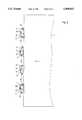
- FIG. 1a and 1b are diagrammatic top plan views of an embodiment of the invention wherein six front lays are distributed over the width or breadth of a feeder table transversely to a paper-sheet conveying direction, the paper sheet being in engagement with all six front lays in FIG. 1a, and being disengaged from four of the six front lays in FIG. 1b;
- FIGS. 2a and 2b are respective side and front elevational views of an embodiment of the front lay stop according to the invention which is formed as a screw;
- FIG. 2c is a view like that of FIG. 2a in another operating phase thereof;
- FIGS. 3a and 3b are views like those of FIGS. 2a and 2b, rerspectively, of another embodiment of the invention, wherein the front lay stop is formed as a pin with an axial groove;
- FIGS. 4a and 4b are side and rear elevational views of a third embodiment of the invention formed with an additional profile for engagement by a tool;
- FIGS. 5a and 5b are views like those of FIGS. 2a and 2b, respectively, for example, of a fourth embodiment of the invention, wherein the front lay stop is formed as a nut;
- FIG. 6 is a view like that of FIG. 1a of a fifth embodiment of the invention.
- FIG. 1a, 1b, 2a and 2b thereof there is shown therein part of a feeder table 7 of a sheet-fed rotary printing press wherein a paper sheet 1, in accordance with the arrow associated therewith, is conveyed from the right-hand to the left-hand sides of FIG. 1a, 1b and 2a over the feeder table 7 in a conventional manner by conventional non-illustrated conveyor means into a region for aligning the paper sheet 1 along the leading edge of the sheet.
- the paper sheets 1 are conveyed so that the leading edge thereof engage respective screw heads 2 of screws 3 distributed symmetrically to the middle of the feeder table 7 transversely to the conveying direction of the sheets 1.
- the leading edge of the sheets 1 thus engages the screw heads and thereby aligns itself.
- the respective screws 3 are screwed with the thread 4 thereof into a respective front lay member 10.
- the thread 4 is a fine thread.
- the screw 3 is formed with a blind bore 9 in an end thereof wherein a spring 8 is received which, at one side, is braced against the screw 3 and, at the other side, against the front lay member 10 and thereby applies a prestressing or loading to the screw 3 for improving automatic locking thereof and for overcoming play.
- the front lay members 10 are fastened to a common front lay shaft 5 so that the axes of the screws 3 are disposed in a common plane and so that stop surfaces 11 formed on the front lay members 10 for limiting the adjusting path of each of the screws 3 lie in a common plane.
- the paper sheets 1 are conveyed over the feeder table 7 from the right-hand towards the left-hand sides of FIG. 1a, 1b and 2a until the leading edge thereof engages the screw heads 2 and the sheets 1 are aligned thereon.
- the respective paper sheets 1 are then taken up by following conveyor means in a conventional manner.
- the front lay member 10 and, accordingly, the screw heads 2 are swiveled in the sheet conveying direction by the swiveling of the front lay shaft 5 in a conventional manner, in the direction represented by the curved solid-line arrow in FIG. 2a, until the the screw head 2 is located below the sheet conveying plane.
- the paper sheet 1 is conveyed by the conveying means over the screw head 2 in the aligned condition thereof to a first printing unit.
- the front lay shaft 5 then swivels back again into the starting position thereof, in the direction represented by the curved broken-line arrow in FIG. 2a, until the stop surface 11 of the front lay shaft 5 is again disposed perpendicularly to the sheet conveying direction.
- the pressman can screw in place individual screw heads 2 into the aligning position, i.e., the position in which the screw head 2 engages the stop surface 11 formed on the front lay member 10, according to FIG. 2c, in accordance with a sheet format or size to be printed or a type or thickness of the paper to be printed or in accordance with any other individual criterion. All of the thus engaged screw heads 2 are thus located on a common line, as shown in FIG. 1a, for example.
- FIG. 1a shows the alignment of a sheet 1 on six screw heads 2 engaged for alignment.
- the four inner screw heads 2' assume a disengaged position in comparison with the view of FIG. 1a, As shown in FIG.
- a knurl 19 is formed at the periphery of the screw head 2 for improving the gripping capability thereof for adjusting the screw head 2.
- a knurl other measures for improving the ability to grip the screw head 2 are conceivable, such as to cover the periphery of the screw head 2 with rubber, for example.
- FIGS. 3a and 3b illustrate an embodiment of the invention wherein paper sheets 1 are aligned on rotationally or axially symmetrical pin heads 13 of pins 14 which have a cylindrical pin body 15 rotatably and axially displaceably mounted in the respective front lay members 10.
- Each pin body 15 is formed with a peripheral groove 16 representing an axial cam wherein a guide pin 17 fastened to the front lay member 10 engages.
- the pin head 13 By turning or twisting the pin head 13, the pin 14 is translatorially shifted axially in and opposite to the conveying direction, respectively, due to the engagement of the guide pin 17 in the peripheral groove 16.
- the pin heads 13 individually employed in the aligning process are adjusted so that they, as in the embodiment of FIGS. 2a, 2b and 2c, are in engagement with the stop surface 11 of the front lay member 10.
- FIGS. 4a and 4b there is shown an embodiment of the invention wherein also screw heads 20 of screws 21, respectively, are screwed in place into respective front lay members 10 which, as in the preceding embodiments, are fastened onto a shaft 5.
- Each of the screws 21 is formed with a thread 22 by which it is screwed into an internally threaded through-bore formed in a respective front lay member 10.
- the screw 21 is formed with a slot 23 in an end thereof located opposite to a screw head 20 thereof.
- the slot 23 is provided so that it may be engaged by a screwdriver for turning the screw 21.
- the screw end opposite the screw head 20 may be provided with suitable profiles corresponding to other tools, or that a remotely-controlled tool may be used for engaging with the screw end.
- the screw head 20 is subjected to pretensioning by a spring 25 located between a sheetmetal cover or cover plate 24 and the screw head 20.
- the cover plate 24 may also be part of a cover lay 26 having an upper edge by which it extends above the screw head 20.
- the paper sheets 1 aligned at the screw head 20 are conveyed away over the cover lay 26 and the screw head 20 by conventional conveyor means after the front lay member 10 has been swiveled away.
- the cover lay 26 thus permits a reliable sliding of the sheet conveyed away over the cover lay 26 without engagement of the screw head 20 by the paper sheet 1.
- FIG. 5 shows an embodiment of the invention wherein a paper sheet 1 is aligned at screw nuts 28 which, respectively, are screwed on a threaded pin 29 fastened into front lay members 10.
- a compression spring 30 is disposed between the screw nut 28 and the front lay member 10 for applying a spring load or prestressing force.
- Additional stop limits as represented by the stop 6 in the embodiment of FIGS. 2a, 2b and 2c, are obviously also conceivable for the other embodiments of the invention.
- the screw nut 28 as well as the pin head 19 and the screw head 21 may also be formed with a knurl or corrugations or with a covering of rubber, for example, in accordance with the embodiment of FIGS. 2a, 2b and 2c, for improving gripping capability.
- measures for accurate adjustment in accordance with the scale 18 of FIG. 2b are also conceivable for the other embodiments of the invention.
- FIG. 6 is a diagrammatic view of an embodiment of the invention wherein leading-edge stops 2 are displaceably mounted by a lower region thereof in a guide groove 31 formed in bodies 32 fastened below the sheet conveying plane, the guide groove 31 extending transversely to the sheet conveying direction.
- the leading-edge stops 2 can be shifted or slid play-free, preferably spring-aided, laterally between limit pins 34 in the guide groove 31, the position thereof in the sheet conveying direction likewise in the intended slight adjustment range being varied, and possibly being readable from a non-illustrated scale.
- Suitable surface shape or design as well as the slight pitch of the guide groove 31 in the sheet conveying direction permit an automatically locking reliable adjustment without any possible unintentional adjustment due to oncoming sheets during the operation.
Landscapes
- Registering Or Overturning Sheets (AREA)
- Dental Tools And Instruments Or Auxiliary Dental Instruments (AREA)
- Body Structure For Vehicles (AREA)
- Radiation-Therapy Devices (AREA)
- Pile Receivers (AREA)
Priority Applications (1)
| Application Number | Priority Date | Filing Date | Title |
|---|---|---|---|
| US08/410,403 US5496023A (en) | 1993-02-27 | 1995-03-27 | Leading edge stop for aligning paper sheets on a feeder table |
Applications Claiming Priority (4)
| Application Number | Priority Date | Filing Date | Title |
|---|---|---|---|
| DE4306238.5 | 1993-02-27 | ||
| DE4306238A DE4306238C2 (de) | 1993-02-27 | 1993-02-27 | Vorderkantenanschlag zum Ausrichten auf dem Anlegetisch |
| US20328694A | 1994-02-28 | 1994-02-28 | |
| US08/410,403 US5496023A (en) | 1993-02-27 | 1995-03-27 | Leading edge stop for aligning paper sheets on a feeder table |
Related Parent Applications (1)
| Application Number | Title | Priority Date | Filing Date |
|---|---|---|---|
| US20328694A Continuation | 1993-02-27 | 1994-02-28 |
Publications (1)
| Publication Number | Publication Date |
|---|---|
| US5496023A true US5496023A (en) | 1996-03-05 |
Family
ID=6481589
Family Applications (1)
| Application Number | Title | Priority Date | Filing Date |
|---|---|---|---|
| US08/410,403 Expired - Lifetime US5496023A (en) | 1993-02-27 | 1995-03-27 | Leading edge stop for aligning paper sheets on a feeder table |
Country Status (5)
| Country | Link |
|---|---|
| US (1) | US5496023A (de) |
| EP (1) | EP0614760B1 (de) |
| JP (1) | JP3388005B2 (de) |
| AT (1) | ATE164347T1 (de) |
| DE (2) | DE4306238C2 (de) |
Cited By (5)
| Publication number | Priority date | Publication date | Assignee | Title |
|---|---|---|---|---|
| US5761998A (en) * | 1996-01-11 | 1998-06-09 | Heidelberger Druckmaschinen Ag | Device for aligning on a feeding table of a sheet-fed printing press |
| US6241241B1 (en) * | 1998-02-04 | 2001-06-05 | Heidelberger Druckmaschinen Ag | Method and device for eliminating rhythmic register errors in sheet-fed rotary printing machines |
| EP1136404A3 (de) * | 2000-03-08 | 2003-01-02 | Bobst S.A. | Vorrichtung zum longitudinalen Ausrichten von plattenförmigen Bauteilen in einer Zuführstation einer Maschine zu ihrer Bearbeitung |
| US6681697B2 (en) | 2001-12-20 | 2004-01-27 | Heidelberger Druckmaschinen Ag | Device for aligning sheets in a feeder of a sheet-processing machine, especially a printing press |
| US20090230609A1 (en) * | 2008-03-17 | 2009-09-17 | Heidelberger Druckmaschinen Aktiengesellschaft | Apparatus for aligning sheets on stops |
Families Citing this family (5)
| Publication number | Priority date | Publication date | Assignee | Title |
|---|---|---|---|---|
| DE4342670C2 (de) * | 1993-12-15 | 1999-04-29 | Heidelberger Druckmasch Ag | Vorrichtung zum Positionieren eines blattförmigen Gegenstandes auf einer Ablagefläche |
| DE10127250B4 (de) | 2000-06-28 | 2018-10-11 | Heidelberger Druckmaschinen Ag | Vorrichtung zum Festlegen der Lage eines Bogens auf einem Anlagetisch |
| DE10218053A1 (de) * | 2002-04-23 | 2003-11-13 | Koenig & Bauer Ag | Einrichtung zum Ausrichten von Bogen |
| DE102007051946A1 (de) * | 2007-10-31 | 2009-05-07 | Koenig & Bauer Aktiengesellschaft | Verfahren und Vorrichtung zum Anpassen von Anschlagflächen der Vordermarken |
| DE102010006718A1 (de) * | 2010-02-02 | 2011-08-04 | Heidelberger Druckmaschinen AG, 69115 | Bogenentspannung |
Citations (12)
| Publication number | Priority date | Publication date | Assignee | Title |
|---|---|---|---|---|
| US168685A (en) * | 1875-10-11 | Improvement in feed-gages for printing-presses | ||
| US1011009A (en) * | 1911-06-02 | 1911-12-05 | Leopold Bakke | Front guide for printing-presses. |
| US1167653A (en) * | 1915-07-23 | 1916-01-11 | Osterlind Printing Press And Mfg Company | Front-feed guide for printing-presses. |
| US2069918A (en) * | 1936-08-26 | 1937-02-09 | Willard Mfg Corp | Stop guide adjustment for printing presses |
| US2113835A (en) * | 1936-10-26 | 1938-04-12 | Challenge Machinery Co | Paper feed guide |
| DE944373C (de) * | 1953-10-25 | 1956-06-14 | Karl Krause Fa | Vorrichtung zum registerhaltigen Anlegen und Foerdern von tafelfoermigen Zuschnitten |
| US3081080A (en) * | 1961-03-27 | 1963-03-12 | Samuel M Langston Co | Adjustable register stop |
| US3993302A (en) * | 1970-07-30 | 1976-11-23 | Miller Printing Machinery Co. | Apparatus for registering and feeding sheets to a sheet fed printing press |
| US4354673A (en) * | 1979-12-20 | 1982-10-19 | Komori Printing Machinery Co., Ltd. | Inadequately fed sheet detectors for use in sheet-fed press |
| US4402266A (en) * | 1981-05-08 | 1983-09-06 | Komori Printing Machinery Co. Ltd. | Front lay device for sheet-fed rotary printing presses |
| EP0374496A2 (de) * | 1988-12-22 | 1990-06-27 | Heidelberger Druckmaschinen Aktiengesellschaft | Einrichtung zum Ausrichten von Voderkanten von Bogen |
| US5297789A (en) * | 1991-10-22 | 1994-03-29 | Heidelberger Druckmaschinen Ag | Device for aligning a leading edge of a sheet |
Family Cites Families (2)
| Publication number | Priority date | Publication date | Assignee | Title |
|---|---|---|---|---|
| DE723416C (de) * | 1938-12-31 | 1942-08-05 | Koenig & Bauer Schnellpressfab | Vorrichtung zum Einstellen der einzeln fuer sich verstellbaren, auf einer hin und her schwingenden Tragspindel angeordneten Anlegemarken |
| DD280295A1 (de) * | 1989-03-02 | 1990-07-04 | Polygraph Leipzig | Vorrichtung zur vorderkantenausrichtung |
-
1993
- 1993-02-27 DE DE4306238A patent/DE4306238C2/de not_active Expired - Fee Related
-
1994
- 1994-01-29 DE DE59405499T patent/DE59405499D1/de not_active Expired - Lifetime
- 1994-01-29 EP EP94101342A patent/EP0614760B1/de not_active Expired - Lifetime
- 1994-01-29 AT AT94101342T patent/ATE164347T1/de not_active IP Right Cessation
- 1994-02-21 JP JP02249594A patent/JP3388005B2/ja not_active Expired - Fee Related
-
1995
- 1995-03-27 US US08/410,403 patent/US5496023A/en not_active Expired - Lifetime
Patent Citations (12)
| Publication number | Priority date | Publication date | Assignee | Title |
|---|---|---|---|---|
| US168685A (en) * | 1875-10-11 | Improvement in feed-gages for printing-presses | ||
| US1011009A (en) * | 1911-06-02 | 1911-12-05 | Leopold Bakke | Front guide for printing-presses. |
| US1167653A (en) * | 1915-07-23 | 1916-01-11 | Osterlind Printing Press And Mfg Company | Front-feed guide for printing-presses. |
| US2069918A (en) * | 1936-08-26 | 1937-02-09 | Willard Mfg Corp | Stop guide adjustment for printing presses |
| US2113835A (en) * | 1936-10-26 | 1938-04-12 | Challenge Machinery Co | Paper feed guide |
| DE944373C (de) * | 1953-10-25 | 1956-06-14 | Karl Krause Fa | Vorrichtung zum registerhaltigen Anlegen und Foerdern von tafelfoermigen Zuschnitten |
| US3081080A (en) * | 1961-03-27 | 1963-03-12 | Samuel M Langston Co | Adjustable register stop |
| US3993302A (en) * | 1970-07-30 | 1976-11-23 | Miller Printing Machinery Co. | Apparatus for registering and feeding sheets to a sheet fed printing press |
| US4354673A (en) * | 1979-12-20 | 1982-10-19 | Komori Printing Machinery Co., Ltd. | Inadequately fed sheet detectors for use in sheet-fed press |
| US4402266A (en) * | 1981-05-08 | 1983-09-06 | Komori Printing Machinery Co. Ltd. | Front lay device for sheet-fed rotary printing presses |
| EP0374496A2 (de) * | 1988-12-22 | 1990-06-27 | Heidelberger Druckmaschinen Aktiengesellschaft | Einrichtung zum Ausrichten von Voderkanten von Bogen |
| US5297789A (en) * | 1991-10-22 | 1994-03-29 | Heidelberger Druckmaschinen Ag | Device for aligning a leading edge of a sheet |
Cited By (7)
| Publication number | Priority date | Publication date | Assignee | Title |
|---|---|---|---|---|
| US5761998A (en) * | 1996-01-11 | 1998-06-09 | Heidelberger Druckmaschinen Ag | Device for aligning on a feeding table of a sheet-fed printing press |
| US6241241B1 (en) * | 1998-02-04 | 2001-06-05 | Heidelberger Druckmaschinen Ag | Method and device for eliminating rhythmic register errors in sheet-fed rotary printing machines |
| EP1136404A3 (de) * | 2000-03-08 | 2003-01-02 | Bobst S.A. | Vorrichtung zum longitudinalen Ausrichten von plattenförmigen Bauteilen in einer Zuführstation einer Maschine zu ihrer Bearbeitung |
| CN1152813C (zh) * | 2000-03-08 | 2004-06-09 | 鲍勃斯脱股份有限公司 | 用于在制板机的横向进给工位中纵向校准板材的装置 |
| US6681697B2 (en) | 2001-12-20 | 2004-01-27 | Heidelberger Druckmaschinen Ag | Device for aligning sheets in a feeder of a sheet-processing machine, especially a printing press |
| US20090230609A1 (en) * | 2008-03-17 | 2009-09-17 | Heidelberger Druckmaschinen Aktiengesellschaft | Apparatus for aligning sheets on stops |
| US7992866B2 (en) * | 2008-03-17 | 2011-08-09 | Heidelberger Druckmaschinen Ag | Apparatus for aligning sheets on stops |
Also Published As
| Publication number | Publication date |
|---|---|
| JP3388005B2 (ja) | 2003-03-17 |
| DE4306238A1 (de) | 1994-09-01 |
| JPH06255083A (ja) | 1994-09-13 |
| DE59405499D1 (de) | 1998-04-30 |
| DE4306238C2 (de) | 1996-06-13 |
| ATE164347T1 (de) | 1998-04-15 |
| EP0614760A1 (de) | 1994-09-14 |
| EP0614760B1 (de) | 1998-03-25 |
Similar Documents
| Publication | Publication Date | Title |
|---|---|---|
| US5496023A (en) | Leading edge stop for aligning paper sheets on a feeder table | |
| GB2098183A (en) | Front lay device for sheet-fed rotary printing presses | |
| US4848230A (en) | Remotely controllable adjusting means for elastically deforming a register rail | |
| US5761998A (en) | Device for aligning on a feeding table of a sheet-fed printing press | |
| US4688483A (en) | Clamping device for a printing plate of an offset printing machine | |
| GB2270517A (en) | Sheet-feeding grippers. | |
| GB2294684A (en) | Feeding sheet material | |
| US5186105A (en) | Device for monitoring sheet movement near the lay marks of sheet-fed offset printing presses | |
| US5361697A (en) | Plate cylinder of a rotary printing press | |
| DE69205461T2 (de) | Vorrichtung zur Positionierung von Druckstücken zum Gebrauch in einer Druckmaschine. | |
| US4641577A (en) | Apparatus for adjusting the plate segment of an off-set lithographic printer | |
| US4896875A (en) | Copy sheet pull guide mechanism | |
| US5415096A (en) | Device for correcting trapezoidal register deviations | |
| GB2293598A (en) | Device for sheet alignment | |
| US5454558A (en) | Side lay device | |
| US5641159A (en) | Synchronizing roller arrangement for transporting sheets into a sheet-processing machine | |
| US5456458A (en) | Device for adjusting the positions of suction grippers on a sheet transfer druw | |
| US6655682B2 (en) | Device for fixing the position of a sheet on a feeding table | |
| US4526364A (en) | Sheet feeding mechanism for duplicating machine with duplexing capability | |
| DE10028070B4 (de) | Vorrichtung zur formatabhängigen Lageerfassung der Bogenvorderkante im Anleger von bogenverarbeitenden Maschinen | |
| US7412925B2 (en) | Device for changing over gripper control in a turning configuration of a sheet-processing machine | |
| US6805260B2 (en) | Device and method for feeding sheets to a sheet-processing machine, especially a printing press | |
| GB2096543A (en) | Adjustments in printing presses | |
| JP2566690B2 (ja) | グリッパ制御装置 | |
| US6505826B2 (en) | Device for separating sheets piled up so as to form a stack, in a feeder of a sheet-processing machine |
Legal Events
| Date | Code | Title | Description |
|---|---|---|---|
| STCF | Information on status: patent grant |
Free format text: PATENTED CASE |
|
| CC | Certificate of correction | ||
| FEPP | Fee payment procedure |
Free format text: PAYOR NUMBER ASSIGNED (ORIGINAL EVENT CODE: ASPN); ENTITY STATUS OF PATENT OWNER: LARGE ENTITY |
|
| FPAY | Fee payment |
Year of fee payment: 4 |
|
| FPAY | Fee payment |
Year of fee payment: 8 |
|
| FPAY | Fee payment |
Year of fee payment: 12 |