US5586202A - Motion detecting apparatus - Google Patents
Motion detecting apparatus Download PDFInfo
- Publication number
- US5586202A US5586202A US08/286,388 US28638894A US5586202A US 5586202 A US5586202 A US 5586202A US 28638894 A US28638894 A US 28638894A US 5586202 A US5586202 A US 5586202A
- Authority
- US
- United States
- Prior art keywords
- sub
- pixels
- data block
- search range
- reference data
- Prior art date
- Legal status (The legal status is an assumption and is not a legal conclusion. Google has not performed a legal analysis and makes no representation as to the accuracy of the status listed.)
- Expired - Fee Related
Links
Images




Classifications
-
- H—ELECTRICITY
- H04—ELECTRIC COMMUNICATION TECHNIQUE
- H04N—PICTORIAL COMMUNICATION, e.g. TELEVISION
- H04N19/00—Methods or arrangements for coding, decoding, compressing or decompressing digital video signals
- H04N19/50—Methods or arrangements for coding, decoding, compressing or decompressing digital video signals using predictive coding
- H04N19/503—Methods or arrangements for coding, decoding, compressing or decompressing digital video signals using predictive coding involving temporal prediction
- H04N19/51—Motion estimation or motion compensation
- H04N19/523—Motion estimation or motion compensation with sub-pixel accuracy
-
- G—PHYSICS
- G06—COMPUTING OR CALCULATING; COUNTING
- G06T—IMAGE DATA PROCESSING OR GENERATION, IN GENERAL
- G06T7/00—Image analysis
- G06T7/20—Analysis of motion
- G06T7/223—Analysis of motion using block-matching
- G06T7/231—Analysis of motion using block-matching using full search
-
- H—ELECTRICITY
- H04—ELECTRIC COMMUNICATION TECHNIQUE
- H04N—PICTORIAL COMMUNICATION, e.g. TELEVISION
- H04N19/00—Methods or arrangements for coding, decoding, compressing or decompressing digital video signals
- H04N19/50—Methods or arrangements for coding, decoding, compressing or decompressing digital video signals using predictive coding
- H04N19/503—Methods or arrangements for coding, decoding, compressing or decompressing digital video signals using predictive coding involving temporal prediction
- H04N19/51—Motion estimation or motion compensation
-
- G—PHYSICS
- G06—COMPUTING OR CALCULATING; COUNTING
- G06T—IMAGE DATA PROCESSING OR GENERATION, IN GENERAL
- G06T2207/00—Indexing scheme for image analysis or image enhancement
- G06T2207/10—Image acquisition modality
- G06T2207/10016—Video; Image sequence
Definitions
- the present invention generally relates to motion detecting apparatus and, more particularly, to a motion detecting apparatus suitable for detecting a motion vector or the like when real moving image data is coded at high efficiency, for example.
- Motion detecting apparatus are used to detect a motion vector when a real moving image data is processed in high efficiency coding process.
- a motion when a motion is detected, for example, in a full search block matching process, a difference absolute value m ij at every pixel is calculated as: ##EQU1## where b ij is a pixel in a search range and a ij is a pixel of reference data block.
- a relation between b i+I+J and a IJ is complex and accordingly, all data (b ij ) of the search range, for example, are written in a memory fabricated within an LSI (large scale integrated circuit) and data b ij corresponding to a IJ is read out from the above memory. Then, the calculation is carried out.
- the conventional apparatus needs an internal memory that when fabricated as an LSI, which unavoidably increases the circuit scale.
- a motion detecting apparatus in which pixels consisting of a predetermined number of pixels within a search range and pixels consisting of pixels of the number smaller than the former pixels within a reference data block are compared on the basis of an arrayed state thereof.
- vector data in 8 directions around the calculated vector are interpolated (i.e., mean value between two points), thereby obtaining predicted images which are shifted by 0.5 pel each.
- a vector is calculated in which a residual between the predicted image and an original image (reference data block) is minimized (i.e, motion is detected at the accuracy of a half pel).
- a i represent 16 pixels of reference data block as shown in FIG. 1B and A i represent 16 pixels corresponding to reference data block in which a motion detection is carried out at 1 pel accuracy within the search range as shown in FIG. 1A.
- a processing is divided into a first stage in which a detection of 1 pixel (1 pel) accuracy is carried out and a second stage in which a detection of 0.5 pel (half pel) is carried out.
- the assignee of the present application has previously proposed a motion detecting apparatus, in which the detection of 1 pel accuracy is carried out on the basis of a so-called full search block matching process. Further, the assignee of the present application has proposed a motion detecting apparatus in which a detection of half pel accuracy is carried out after a detection of one pel accuracy is carried out.
- a motion detection of one pel accuracy when a motion detection of one pel accuracy is carried out, a sum of difference absolute values of respective pixels within a reference data block and corresponding pixels within a search range is calculated at every corresponding state of pixels which can be treated by a reference data block of g ⁇ p pixels within the search range of, for example, e ⁇ f pixels and the position of the block formed of g ⁇ p pixels in which the above sum becomes minimum is detected.
- a motion detection of a half pel accuracy when a motion detection of a half pel accuracy is carried out, then a mean value between adjacent pixels and a pixel within a reference data block are compared and difference absolute value sums are obtained at every corresponding state with respect to the pixels within the reference data block.
- the above-mentioned proposed apparatus can perform a motion detection of one pel accuracy at g ⁇ p cycles and can perform a real time processing.
- (g+2) ⁇ (p+2) cycles must be provided for performing its process.
- the processing speed of the apparatus which carries out the motion detection of half pel accuracy must be increased by (g+2) ⁇ (p+2)/g ⁇ p times, which needs a special apparatus.
- complicated circuits also must be provided in order to transfer image data.
- a motion detecting apparatus in which when pixels within a search range formed of a predetermined number of pixels and pixels within a reference data block the pixel number of which is smaller than the predetermined number of pixels are compared on the basis of the arrangement state thereof, there is provided a processing circuit for processing sums of difference absolute values of respective pixels within the reference data block and corresponding pixels within the search range formed at every search range, to thereby detect a motion state on the basis of the sums.
- This motion detecting apparatus is characterized in that respective pixels within the search range are input to the processing circuit at a set time and pixels within the search range are input to the processing circuit at the set time, thereby being sequentially processed with corresponding pixels within the data block.
- a motion detecting apparatus in which pixels within a search range formed of pixels of a predetermined number and pixels within a reference data block formed of pixels of the number smaller than the predetermined pixel number are compared on the basis of the arrayed state to thereby detect the motion state of pixels within the search range is comprised of an input unit to which pixels within the search range are input in a predetermined order, a calculating circuit for calculating a difference absolute value between the pixels within the search range and the corresponding pixels within the reference data block,and a detecting circuit for detecting the motion state on the basis of the calculated result, wherein the calculating circuit calculates a difference absolute value between pixels within the block and the corresponding pixels within the search range at every corresponding state of pixels which can be treated by the block within the search range and the calculation is carried out in parallel to each the corresponding state in accordance with the sequential order.
- a motion detecting apparatus having a processing circuit for processing sums of difference absolute values of pixels within a reference data block formed by pixels of the number smaller than the predetermined pixel number and corresponding pixels within a search range formed by pixels of a predetermined number at every corresponding state of pixels of the block within the search range when pixels within the search range and pixels of the reference data block are compared on the basis of the arrayed state and in which the pixels within the search range are input to the processing circuit at a predetermined input cycle and pixels within the search range are input to the processing circuit on the basis of the cycle to thereby sequentially process the difference absolute value sum between corresponding pixels within the reference data block and pixels within the reference data block is characterized in that when a motion of less than one pixel is detected within the search range, a mean value between adjacent pixels and the pixel within the block are compared, the difference absolute value is obtained at every corresponding state with respect to the pixels within the block and a common processing between the corresponding states is carried out with a priority.
- a motion detecting apparatus is comprised of a first processing circuit for processing sums of difference absolute values of pixels within a first reference data block formed by pixels of the number smaller than the predetermined pixel number and corresponding pixels within a search range formed by pixels of a predetermined number at every corresponding state of pixels of the block within the search range when pixels within the search range and pixels of the first reference data block are compared on the basis of the arranged state, and a second processing circuit for comparing a mean value of adjacent pixels and pixels within a second reference data block when a motion of less than one pixel within the search range is detected to thereby obtain a difference absolute value at every corresponding state with respect to the pixels within the second reference data block, wherein the number of pixels of the second reference data block is smaller than that of pixels within the first reference data block.
- FIGS. 1A and 1B are respectively schematic diagrams used to explain a motion detection of 1 pel accuracy according to the prior art
- FIG. 2 is a schematic diagram used to explain a motion detection of a half pel accuracy according to the prior art
- FIG. 3 is a conceptual diagram showing an arrangement of a first embodiment of a motion detecting apparatus according to the present invention
- FIGS. 4A and 4B are respectively schematic diagrams used to explain the first embodiment
- FIGS. 5A and 5B are respectively schematic diagrams used to explain the first embodiment
- FIG. 6 is a schematic diagram showing an example of a difference absolute value calculating circuit used in the first embodiment
- FIG. 7 is a schematic diagram showing an example of a difference absolute value sum calculating circuit used in the first embodiment
- FIG. 8 is a schematic diagram showing another example of the difference absolute value calculating circuit used in the first embodiment.
- FIG. 9 is a schematic diagram showing another example of the difference absolute value sum calculating circuit used in the first embodiment.
- FIG. 10 is a schematic block diagram showing an example of the motion detecting apparatus which can be simplified by the time-division-multiplexing manner
- FIG. 11 is a schematic diagram used to explain the case such that the full search block matching is generalized
- FIG. 12 is a conceptual diagram showing an arrangement of an example of a generalized motion detecting apparatus
- FIG. 13 is a schematic block diagram showing an arrangement of a second embodiment of the motion detecting apparatus according to the present invention.
- FIG. 14 is a schematic diagram used to explain the second embodiment
- FIG. 15 is a schematic diagram used to explain the second embodiment
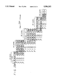
- FIG. 16 is a timing chart used to explain operation of the second embodiment of the motion detecting apparatus according to the present invention.
- FIG. 17 is a block diagram showing an arrangement of a main portion of the second embodiment of the motion detecting apparatus according to the present invention.
- FIG. 18 is a schematic block diagram showing an arrangement of a third embodiment of the motion detecting apparatus according to the present invention.
- FIG. 19 is a schematic diagram showing a first reference data block used in the third embodiment.
- FIGS. 20A and 20B are schematic diagrams used to explain a search range, respectively;
- FIGS. 21A and 21B are respectively diagrams showing a search range of a second stage in which a motion is detected at one pel accuracy
- FIG. 22 is a diagram showing a second reference data block
- FIGS. 23A through 230 are respectively timing charts used to explain operation of the whole of the motion detecting apparatus according to the third embodiment of the present invention.
- FIGS. 24A through 24N are respectively timing charts used to explain operation of a main portion of the motion detecting apparatus according to the third embodiment of the invention.
- FIG. 25 is a conceptual diagram of the third embodiment of the motion detecting apparatus according to the present invention.
- FIG. 3 shows a conceptual diagram of a first embodiment of a motion detecting apparatus according to the present invention.
- a full search block matching process in which a search range is composed of 5 ⁇ 5 pixels and a reference data block is composed of 3 ⁇ 3 pixels in order to obtain a motion vector in a range of from ( ⁇ 1) ⁇ ( ⁇ 1) pixels is described as a specific example, such full search block matching process can be generalized (search range is composed of e ⁇ f pixels and reference data block is composed of g ⁇ p pixels).
- pixels b ij in the search range and pixels a ij in the reference data block are arranged as shown in FIGS. 4A and 4B.
- an upper leftmost suffix of the pixel in the search range is represented by (00).
- difference absolute value sums m ij when motion vectors are expressed as (ij) is expressed by the following equation (3): ##EQU2##
- reference numeral 1 depicts a difference absolute value calculating circuit in which 9 means for calculating the above-mentioned difference absolute values are provided in parallel.
- the difference absolute value calculating circuit 1 includes four input terminals 11 and data A K to D K are respectively supplied to these input terminals 11 at k'th cycle.
- data B, D at 2nd and 5th cycles, data C, D at 6th and 7th cycles and data B, C, D at 8th cycle are not utilized in actual calculation as is clear from the equation (5) and therefore arbitrary dummy data are supplied to the input terminals 11 as data between the above-mentioned data.
- the difference absolute value calculating circuit 1 derives 9 values of respective terms at every cycle.
- the difference absolute value sum calculating circuit 2 is comprised of 9 adding means and 9 registers (unit delay means) provided in parallel.
- 9 adding means Nine data of 0'th term supplied at the 0'th cycle are stored in the 9 registers.
- Nine data of 0'th term stored in the registers are added to 9 data of the 1st term supplied at the 1st cycle and then stored in the 9 registers.
- 9 data of 2nd through 8th terms supplied at the 2nd to 8th cycles are sequentially added to 9 data stored in the registers, whereby the addition of respective terms is carried out in each equation of equation 5 to calculate the difference absolute values m ij .
- the difference absolute values m ij obtained by the difference absolute value sum calculating circuit 2 are supplied to a difference absolute value sum comparing circuit 3 which obtains the minimum m ij . Then, (ij) is supplied to an output terminal 31 as a motion vector.
- FIG. 6 shows a specific example of the difference absolute value calculating circuit 1.
- 9 absolute value calculating means (simply referred to as DA in FIG. 6)
- U 00 to U 22 and pixels a 00 to a 22 of respective reference data blocks are supplied to these calculating means U 00 to U 22 .
- these calculating means U 00 to U 22 are respectively supplied with data A K to D K selected by 4-input selectors V 00 to V 22 from the input terminal 11.
- the 4-input selectors V 00 to V 22 are respectively supplied with control signals w 0 to w 2 and x 0 to x 2 as shown in FIG. 6.
- control signals w and x are both low in level, then data A K is selected; when the control signal w is high in level and the control signal x is low in level, then the data B K is selected; when the control signal w is low in level and the control signal x is high in level, then the data C K is selected; and when the control signals w and x are both high in level, then the data D K is selected. Further, these control signals w 0 to w 2 and x 0 to x 2 are supplied in response to the cycles as shown on the following table 1.
- the respective calculating means U 00 to U 22 derive values I 00 to I 22 of terms involving a 00 to a 22 in the equation (5) at every cycle. Assuming that I ij (t) is a value of I ij of t'th cycle, then the above-mentioned equation (5) is rewritten as:
- FIG. 7 shows a specific example of the difference absolute value sum calculating circuit 2.
- 9 adding means W 00 to W 22 and 9 registers X 00 to X 22 are respectively supplied with the above-mentioned values I 00 to I 22 .
- Outputs of these adding means W 00 to W 22 are respectively supplied to the registers X 00 to X 22 .
- the registers X 00 to X 22 are driven at every cycle by a pulse similar to a data rate and reset at the 0'th cycle in response to a clear pulse.
- Outputs of these registers X 00 to X 22 are connected cyclically in the longitudinal direction through one of the terminals of 2-input selectors Y 00 to Y 22 and also connected cyclically in the lateral direction through the other terminals of the 2-input selectors Y 00 to Y 22 .
- the selectors Y 00 to Y 22 are connected to the first terminals at 1st, 2nd, 4th, 5th, 7th and 8th cycles and are connected to the other terminals at 0'th, 3rd and 6th cycles.
- the difference absolute value sum m ij is stored in each of the registers X 00 to X 22 .
- the storage position of the difference absolute value sum m ij is a point symmetry position with respect to the suffixes of the registers X 00 to X 22 about X ii .
- the difference absolute value sums m ij stored in these registers X 00 to X 22 are supplied to the comparing circuit 3 at the completion of the 8th cycle which then obtains the minimum m ij , thereby the motion vector (ij) being calculated.
- a specific example of the comparing circuit 3 is well known and therefore need not be described.
- FIG. 8 shows another specific example of the difference absolute value calculating circuit 1.
- the 9 difference absolute value calculating means (simply referred to as DA in FIG. 8) U 00 to U 22 are cyclically supplied with the pixels a 00 to a 22 of respective reference data blocks, respectively. That is, 9 registers Z 00 to Z 22 are provided and outputs of these registers Z 00 to Z 22 are respectively supplied to the calculating means U 00 to U 22 . Also, these registers Z 00 to Z 22 are cyclically coupled in the lateral direction. The pixels a 00 to a 22 are respectively stored in the registers Z 00 to Z 22 and these registers Z 00 to Z 22 are respectively supplied with a clock whose frequency is 1/3 of the input data rate.
- the calculating means U 00 to U 22 are cyclically supplied with the pixels a 00 to a 22 at every three cycles. Further, the control signals W 0 to W 2 and X 0 to X 2 supplied to the selectors V 00 to V 22 are supplied in response to the corresponding cycles as shown on the following table 2.
- the calculating means U 00 to U 22 derive values h 00 to h 22 of the terms involving a 00 to a 22 of the equation (5) at each cycle. Assuming that h ij (t) is a value of h ij of the t'th cycle, then we have:
- FIG. 9 shows another specific example of the difference absolute value sum calculating circuit 2.
- adding means W 00 to W 22 and 9 registers X 00 to X 22 respectively.
- These adding means W 00 to W 22 are respectively supplied with the above-mentioned values h 00 to h 22 and outputs of these adding means W 00 to W 22 are respectively supplied to the registers X 00 to X 22 .
- These registers X 00 to X 22 are driven at every cycle by a pulse similar to the data rate and reset at 0'th cycle in response to a clear pulse supplied thereto.
- the difference absolute value sums m ij stored in these registers X 00 to X 22 are supplied to the comparing circuit 3 at the end of the 8th cycle, wherein the minimum m ij is obtained to calculate the motion vector (ij).
- a specific example of the comparing circuit 3 is well known and therefore need not be described herein. In this fashion, the difference absolute value calculating circuit 1 and the difference absolute value sum calculating circuit 2 can be realized.
- FIG. 10 shows other example of the motion detecting apparatus of the present invention, in which the difference absolute value calculating circuit 1 of FIG. 8 and the difference absolute value sum calculating circuit 2 of FIG. 9 are driven in a triple time division processing fashion.
- 3 difference absolute value calculating means U 0 to U 2 and 9 registers Z 00 to Z 22 also are provided so as to form three cyclic loops in the lateral direction.
- Outputs of these registers Z 00 to Z 22 are selected by 3-input selectors S 0 to S 2 and then fed to the calculating means U 0 to U 2 . Further, 3 adding means W 0 to W 2 are provided and 9 registers X 00 to X 2 are connected in cascade. When these circuits are driven by a pulse whose frequency is three times as high as the data rate, the processing similar to the above can be carried out. The number of the calculating means and the adding means can be reduced as set forth above.
- the full search block matching processing in which the search range is formed of 5 ⁇ 5 pixels and the reference data block is formed of 3 ⁇ 3 pixels is described. If this full search block matching processing is generalized in which, for example, the search range is formed of e ⁇ f pixels and the reference data block is formed of g ⁇ p pixels, then the motion detecting apparatus is operated as follows. In that event, the motion vector can be obtained in a range of [ ⁇ (e-g)/2] ⁇ [ ⁇ (f-p)/2]. That is, the search range of e ⁇ f pixels is divided at every g ⁇ p pixels and then the processing is carried out as shown in FIG. 11.
- (e-g+1) ⁇ (f-p+1) outputs from this difference absolute value calculating circuit 1 are supplied to the difference absolute value sum calculating circuit 2 composed of (e-g+1) ⁇ (f-p+1) adding means W and registers X. Then, (e-g+1) ⁇ (f-p+1) outputs from the difference absolute value sum calculating circuit 2 are supplied to the comparing circuit 3 which then obtains the minimum difference absolute value sum, thereby the motion vector being calculated. Also, in accordance with this circuit, the number of the calculating means and the adding means can be reduced in a time division multiplexed processing similar to the above one.
- the internal memory becomes unnecessary and the satisfactory motion detection can be carried out by the simple circuit arrangement.
- the number of additions can be reduced by bracketing a common term of 8 equations except sum (0,0). Further, by properly operating the input sequence of pixels, .left brkt-top.(A I +A J )/2.right brkt-bot. and .left brkt-top.a K .right brkt-bot. can be associated with ease and therefore the circuit scale of the motion detecting apparatus can be reduced. More specifically, according to the second embodiment, the above-mentioned equation (2) is modified as the following equation (8):
- FIG. 13 shows an arrangement of the motion detecting apparatus of this embodiment.
- the above data A is supplied to an input terminal 10 and this data is shifted by one bit and then the value is reduced to a half by means 12.
- the resultant 1/2 value is supplied to registers 13a to 13n connected in series.
- the resultant 1/2 value and outputs of the registers 13a, 13b, 13f, 13h, 13l, 13m and 13n are respectively supplied-to adders 14a through 14h.
- the above-mentioned data a is supplied to an input terminal 15.
- the data a at the input terminal 15 is supplied to a subtracter 16 and the output of the register 13g is supplied to the subtracter 16, in which the data a supplied to the input terminal 15 is subtracted from this value or output of the register 13g.
- a subtracted output from the subtracter 16 is supplied to the adders 14a through 14h.
- Added outputs from the adders 14a to 14h are respectively supplied through absolute value generating circuits (simply referred to as ABS in FIG. 13) 17a to 17h to accumulative-adder circuits (simply referred to as ACD in FIG. 13) 18a to 18h.
- the accumulative-adder circuits 18a to 18h are supplied with an enable control signal from a terminal 19.
- the residual S of the motion vector calculated by the above-mentioned motion detection of one pel accuracy is supplied to an input terminal 20. Then, the value of the residual S from the input terminal 20 and the added outputs from the accumulative-adder circuits 18a through 18h are supplied to a comparing circuit 30 which detects the minimum value. Then, a motion vector of the half pel accuracy is supplied to an output terminal 32.
- data A i is input to the input terminal 10 at the i'th cycle and data a i is input to the input terminal 15 at the i'th cycle.
- a 0 to a 13 , a 18 , a 19 , a 24 , a 25 , a 30 , and a 31 are not shown in FIG. 1B, dummy data are input to the input terminal 15 at corresponding 0'th to 13th, 18th, 19th, 24th, 25th, 30th and 31st cycles.
- the register 13g derives .left brkt-top.value which results from multiplying the value input to the input terminal 10 by 1/2 time and delaying the same by 7 cycles.right brkt-bot., i.e., .left brkt-top.A 7 /2.right brkt-bot. and at the same time, data .left brkt-top.a 14 .right brkt-bot. is input to the input terminal 15, whereby the subtracter 16 calculates [(A 7 /2)-a 14 ].
- the register 13n derives .left brkt-top.value which results from multiplying the value input to the input terminal 10 by 1/2 time and delaying the same by 14 cycles.right brkt-bot., i.e., .left brkt-top.A 0 /2.right brkt-bot., whereby the adder 14h calculates [(A 0 /2)+ ⁇ (A 7 /2)-a 14 ⁇ .
- the calculated value is converted into an absolute value [
- the value [(A 7 /2)-a 14 ] calculated by the subtracter 16 is also input to the adders 14a to 14g so that [(A 14 /2)+ ⁇ (A 7 /2)-a 14 ⁇ ], [(A 13 /2)+ ⁇ (A 7 /2)-a 14 ⁇ ], [(A 12 /2)+ ⁇ (A 7 /2)-a 14 ⁇ ], [(A 8 /2)+ ⁇ (A 7 /2)-a 14 ⁇ ], [(A 6 /2)+ ⁇ (A 7 /2)-a 14 ⁇ ], [(A 2 /2)+ ⁇ (A 7 /2)-a 14 ⁇ ] and [(A 1 /2)+ ⁇ (A 7 /2)-a 14 ⁇ ]
- values of .left brkt-top.5th to 8th terms of the right side of sum (-0.5, -0.5) of the equation (8).right brkt-bot. are input to and then accumulatively added to the accumulatively-added result by the accumulative-adder 18h. Since undesirable data are input to the accumulative-adder 18h at the 24th and 25th cycles, by making the enable control signal from the terminal 19 low in level (off), these undesirable data can be inhibited from being accumulatively added to the accumulatively-added result.
- values of .left brkt-top.9th to 12th terms of the right side of sum (-0.5, -0.5) on the-equation (8).right brkt-bot. are input to and accumulatively added to the existing accumulatively added result. Since undesirable data are input to the accumulative-adder 18h at the 30th and 31st cycles, by making the enable control signal at the terminal 19 low in level (off), these undesirable data can be inhibited from being accumulatively added to the existing accumulatively added result.
- the register 13n derives the values of A 0 to A 21 shown by arrows in FIG. 14 in the form of 1/2 time of the data input to the input terminal 10. Then, the accumulative-adder 18h accumulatively adds the values shown by the hatched areas in FIG. 14 according to the following equation:
- I, J and K are the values of the 16th term appearing in the equation (8).
- the values of A 4 , A 5 , A 10 , A 11 , A 16 , A 17 (18th, 19th, 24th, 25th, 30th and 31st cycles) are not accumulatively added because the enable control signal is made low in level (off).
- the register 13m derives the values of A 1 to A 22 shown by arrows in FIG. 15 in the form of 1/2 time of the data input to the input terminal 10. Then, the accumulative-adder 18g accumulatively adds the values shown by the hatched areas in FIG. 15 according to the following equation:
- I, J and K are the values of the 16th term appearing on the equation (8).
- the values of A 5 , A 6 , A 11 , A 12 , A 17 , A 18 (18th, 19th, 24th, 25th, 30th and 31st cycles) are not accumulatively added because the enable control signal at the terminal 19 is made low in level (off).
- (1) represents the values input to the input terminal 10
- (2) to (10) represent values which result from dividing the data of the registers 13n, 13m, 13l, 13h, 13g, 13f, 13b, 13a and the data A by half (1/2)
- (11) represents the values input to the input terminal 15
- (12) represents the enable control signal input to the input terminal 19.
- the motion detection of half pel accuracy can be carried out by the motion detecting apparatus of simple arrangement.
- the adders 14a to 14h, the absolute value generating circuits 17a to 17h and the accumulative-adders 18a to 18h can be realized as, for example, shown in FIG. 17.
- a value [1] selected by a switch 73 is supplied to the lowest-order side (carry in: Ci) of the adder 81, whereby the value from the adder 24 is converted into the absolute value, which is then input to the adder 81.
- the output of the adder 81 is fed through a unit delay element (register) 82 back thereto.
- the register 82 is provided with an enable terminal EN and an enable control signal from a terminal 29 is supplied to the enable terminal EN, whereby the accumulative addition in which undesirable values are inhibited from being added is carried out.
- FIG. 17 Only one system of this calculating circuit is illustrated in FIG. 17. When 8 values are calculated as described above, 8 systems of this calculating circuits are provided in parallel. Alternatively, if there is a tolerance in the calculation processing time, the calculating circuit can be realized only by one system according to the eightfold time division multiplexing manner. In that case, the circuit can be reduced to about 1/8 in scale.
- the reference data block is formed of 4 ⁇ 4 pixels as described above, this reference data block can be generalized to provide an arbitrary reference data block of g ⁇ p pixels.
- the motion detection of half pel accuracy can be carried out by the motion detecting apparatus of simple arrangement.
- FIG. 18 shows in block form an arrangement of the third embodiment of the motion detecting apparatus according to the present invention. While the search range is formed of 11 ⁇ 11 pixels and the reference data block is formed of 6 ⁇ 6 pixels in the third embodiment, it is needless to say that the search range and the reference data block can be generalized (i.e., search range is formed of e ⁇ f pixels and reference data block is formed of g ⁇ p pixels).
- the pixels a I input to the input terminal 100 are stored in a shift register 102 of 36 stages and then fed to a motion detecting circuit 103 of one pel accuracy.
- pixels (one frame-preceding pixels) of the search range are supplied to an input terminal 104 in the sequential order shown, for example, in FIG. 20A.
- the respective pixels from the input terminal 104 are supplied to an input terminal D of the motion detecting circuit 103 and also supplied through a delay circuit 105 having a delay time of 36 cycle periods to an input terminal C of the motion detecting circuit 103.
- the respective pixels from the input terminal 104 are supplied through a delay circuit 106 having a delay time of 6 horizontal periods to an input terminal B of the motion detecting circuit 103 and supplied through a further delay circuit 107 having a delay time of 36 cycle periods to an input terminal A of the motion detecting circuit 103.
- the motion detecting circuit 103 is supplied with respective pixels as shown in FIG.
- search range is formed of 11 ⁇ 11 pixels, then respective pixels of B 5 . . . B 35 , C 30 to C 35 , D 5 . . . D 29 to C 35 shown by hatched areas are pixel data outside of the search range and then regarded as dummy data, respectively.
- the motion detecting circuit 103 carries out the motion detection of one pel accuracy. More specifically, this motion detecting circuit 103 includes, for example, 36 difference absolute value calculating circuits and accumulative-adders and a comparing circuit which compares these accumulatively-added values and calculates the following equation (11) in response to values of the respective pixels a I supplied thereto from the above-mentioned shift register 102 and values of the respective pixels A k to D K supplied to the input terminals A to D:
- the respective pixels from the delay circuit 105 are supplied to a contact D of a change-over switch 112 and also supplied through a delay circuit 113 having a delay time of 36 cycle periods to a contact C of the change-over switch 112. Further, the respective pixels from the delay circuit 107 are supplied to a contact B of the change-over switch 112 and also supplied through a delay circuit 114 having a delay time of 36 cycle periods to a contact A of the change-over switch 112.
- the motion vector (i,j) thus detected of one pel accuracy is supplied through the latch circuit 108 to a control circuit 115 and the change-over switch 115 is selectively connected to the contacts A to D in response to the signal from the control circuit 115.
- respective pixels A K to D K shown in FIG. 21A are supplied from the change-over switch 112 in response to the motion vector (i,j) in the sequential order of suffixes.
- the motion vector (i,j) of one pel accuracy from the latch circuit 108 is supplied to a memory control circuit 116 and a write address (WA) generated by this memory control circuit 116 is supplied to RAMs (random access memories) 117a and 117b, each having a storage capacity of 36 words.
- RAMs random access memories
- the pixels A K to D K supplied from the change-over switch 112 in the sequential order of suffixes are written in the respective addresses of the RAMs 17a and 17b as shown in FIG. 21B.
- a ring counter 118 is adapted to generate values of 0 to 35, and the values from the ring counter 118 are supplied to read addresses (RA) of the RAMs 117a and 117b.
- switches 119 and 120 are adapted to switch the RAMs 117a and 117b at every 36 cycles in a bank fashion so that the reading and/or writing is alternately carried out, which can make the processing continuous.
- the respective pixels A' K from the switch 120 are supplied to a motion detecting circuit 121 of half pel accuracy.
- the respective pixels a I of reference data block passed through the shift register 102 are supplied through a delay circuit 122 having delay time of 72 cycle periods and a delay circuit 123 having delay time of 7 cycle periods to the motion detecting circuit 121 of half pel accuracy.
- the residual S provided when the motion vector (i,j) of one pel accuracy is detected by the motion detecting circuit 103 of one pel accuracy is supplied through latch circuits 124, 125 to the motion detecting circuit 121 of half pel accuracy.
- FIGS. 23A-O show the entire timing chart of this motion detecting apparatus. That is, FIG. 23A shows a value input to the input terminal 100, FIGS. 23 B-E show values input to the input terminals A to D of the motion detecting circuit 103, respectively, FIG. 23F shows motion vector (i,j) of one pel accuracy from the latch circuit 108, FIGS. 23G-J show values supplied to the terminals A to D of the switch 112, respectively, FIG. 23K shows a value derived from the delay circuit 122 of 72 cycle periods, FIG. 23L shows a residual S provided by the latch circuit 125 when the motion vector (i,j) of one pel accuracy is detected, FIG. 23M shows a value derived from the switch 120, FIG. 23N shows an integer portion of the motion vector developed at the output terminal 111 and FIG. 23O shows a decimal portion of the motion vector developed at the output terminal 127.
- FIGS. 24A-N show a timing chart between the switches 112 and 120.
- FIGS. 24A-D show values supplied to the terminals A to D of the switch 112.
- FIG. 24E shows the write address (WA) supplied to the RAMs 117a and 117b, whereby the inputs to the RAMs 117a and 117b shown in FIG. 24F are written in these addresses to generate the values A' K shown in FIG. 24G.
- the values A' K are derived from the switch 120 in the sequential order of suffixes.
- the number of the pixels of the second reference data block (delay circuit 122) is made smaller than that of the pixels supplied to the first reference data block (input terminal 100)
- the number of the processing cycles in the second processing means (motion detecting circuit 121 of half pel accuracy) can be made equal to that of the processing cycles in the first processing means (motion detecting circuit 103 of one pel accuracy) and the problems of processing speed and of image data transfer can be solved, which can make it possible to carry out the motion detection of half pel accuracy by the simple arrangement.
- the numbers of processing cycles of the first processing means (motion detecting circuit 103 of one pel accuracy) and of the second processing means (motion detecting circuit 121 of half pel accuracy) can both be made 36 cycles, which can make it possible to carry out the motion detection of half pel accuracy in a real time fashion.
- FIG. 25 shows a conceptual diagram of the above-mentioned third embodiment of the motion detecting apparatus.
- data of the first reference data block of 6 ⁇ 6 pixels supplied, for example, to the input terminal 100 and data of the search range of 11 ⁇ 11 pixels supplied to the input terminal 104 are supplied to the motion detecting circuit 103 of one pel accuracy which then detects the motion vector of one pel accuracy.
- 6 ⁇ 6 pixels corresponding to the motion vector of one pel accuracy detected by the motion detecting circuit 103 are supplied to the motion detecting circuit 121 of half pel accuracy as the search range (shown by hatched areas: contents of RAMs 117a and 117b), and the motion detecting circuit 121 of half pel accuracy detects a motion vector of half pel accuracy on the basis of 4 ⁇ 4 pixels (shown by the hatched areas) of the respective pixels from the delay circuit 122 as the second reference data block. Then, the motion vectors of one pel accuracy and of half pel accuracy thus detected are delivered to the output terminals 111 and 127, respectively.
- the search range is formed of 11 ⁇ 11 pixels and the first reference data block is formed of 6 ⁇ 6 pixels as described above, the present invention is not limited thereto and the search range may be generalized as e ⁇ f pixels and the reference data block may be generalized as g ⁇ p pixels. Further, in the above-mentioned third-embodiment of the motion detecting apparatus, the motion detecting circuit 103 of one pel accuracy and the motion detecting circuit 121 of half pel accuracy are not limited thereto and may be applied to arbitrary apparatus.
- the number of the pixels of the second reference data block is made smaller than that of the pixels of the first reference data block, the number of the processing cycles in second processing means can be made equal to the processing cycles in the first processing means and the problems of processing speed and of image data transfer can be solved, which can make it possible to carry out the motion detection of half pel accuracy by the simple arrangement.
Landscapes
- Engineering & Computer Science (AREA)
- Multimedia (AREA)
- Signal Processing (AREA)
- Computer Vision & Pattern Recognition (AREA)
- Physics & Mathematics (AREA)
- General Physics & Mathematics (AREA)
- Theoretical Computer Science (AREA)
- Compression Or Coding Systems Of Tv Signals (AREA)
Priority Applications (1)
| Application Number | Priority Date | Filing Date | Title |
|---|---|---|---|
| US08/286,388 US5586202A (en) | 1991-01-31 | 1994-08-05 | Motion detecting apparatus |
Applications Claiming Priority (8)
| Application Number | Priority Date | Filing Date | Title |
|---|---|---|---|
| JP3-010551 | 1991-01-31 | ||
| JP03010551A JP3136616B2 (ja) | 1991-01-31 | 1991-01-31 | 動き検出装置 |
| JP3014310A JP3038935B2 (ja) | 1991-02-05 | 1991-02-05 | 動き検出装置 |
| JP3-014310 | 1991-02-05 | ||
| JP3022302A JP2906684B2 (ja) | 1991-02-15 | 1991-02-15 | 動き検出装置 |
| JP3-022302 | 1991-02-15 | ||
| US82799192A | 1992-01-29 | 1992-01-29 | |
| US08/286,388 US5586202A (en) | 1991-01-31 | 1994-08-05 | Motion detecting apparatus |
Related Parent Applications (1)
| Application Number | Title | Priority Date | Filing Date |
|---|---|---|---|
| US82799192A Continuation | 1991-01-31 | 1992-01-29 |
Publications (1)
| Publication Number | Publication Date |
|---|---|
| US5586202A true US5586202A (en) | 1996-12-17 |
Family
ID=27279005
Family Applications (1)
| Application Number | Title | Priority Date | Filing Date |
|---|---|---|---|
| US08/286,388 Expired - Fee Related US5586202A (en) | 1991-01-31 | 1994-08-05 | Motion detecting apparatus |
Country Status (2)
| Country | Link |
|---|---|
| US (1) | US5586202A (de) |
| EP (1) | EP0497586A3 (de) |
Cited By (35)
| Publication number | Priority date | Publication date | Assignee | Title |
|---|---|---|---|---|
| WO1997022083A1 (en) * | 1995-12-12 | 1997-06-19 | Massachusetts Institute Of Technology | Method and apparatus for motion estimation in a video signal |
| US5838827A (en) * | 1994-11-10 | 1998-11-17 | Graphics Communication Laboratories | Apparatus and method for searching motion vector |
| US5883969A (en) * | 1995-06-01 | 1999-03-16 | Aerospatiale Societe Nationale Industrielle | Procedure and device for detecting the movement of a target and their applications |
| US5956434A (en) * | 1995-03-31 | 1999-09-21 | Shibata; Tadashi | Semiconductor operational circuit |
| US5987178A (en) * | 1996-02-22 | 1999-11-16 | Lucent Technologies, Inc. | Apparatus and method for a programmable video motion estimator |
| US6023520A (en) * | 1995-07-06 | 2000-02-08 | Hitach, Ltd. | Method and apparatus for detecting and displaying a representative image of a shot of short duration in a moving image |
| US6049623A (en) * | 1995-12-21 | 2000-04-11 | U.S. Philips Corporation | Directional adaptive noise reduction |
| US6111984A (en) * | 1997-06-10 | 2000-08-29 | Fujitsu Limited | Method for matching input image with reference image, apparatus for the same, and storage medium storing program for implementing the method |
| US6192322B1 (en) * | 1996-04-19 | 2001-02-20 | Raytheon Company | Moving object and transient event detection using rotation strip aperture image measurements |
| US6215823B1 (en) * | 1997-12-31 | 2001-04-10 | Lg Electronics Inc. | Motion vector decoder |
| US6298144B1 (en) | 1998-05-20 | 2001-10-02 | The United States Of America As Represented By The National Security Agency | Device for and method of detecting motion in an image |
| US20030005267A1 (en) * | 2001-06-21 | 2003-01-02 | Koba Igor M. | System and method for parallel computing multiple packed-sum absolute differences (PSAD) in response to a single instruction |
| US20030118105A1 (en) * | 1999-03-29 | 2003-06-26 | Sony Corporation | Image processing device, image processing method, and storage medium |
| US20040062308A1 (en) * | 2002-09-27 | 2004-04-01 | Kamosa Gregg Mark | System and method for accelerating video data processing |
| US20040081335A1 (en) * | 2001-06-20 | 2004-04-29 | Tetsujiro Kondo | Image processing device and method, and imager |
| US20050162393A1 (en) * | 2003-10-29 | 2005-07-28 | Jung-Hong Ahn | Method of calculating sub-pixel movement and position tracking sensor using the same |
| US20060140451A1 (en) * | 2004-12-24 | 2006-06-29 | Lite-On Semiconductor Corp. | Motion detection method |
| US7095321B2 (en) | 2003-04-14 | 2006-08-22 | American Power Conversion Corporation | Extensible sensor monitoring, alert processing and notification system and method |
| US7148796B2 (en) | 2003-04-14 | 2006-12-12 | American Power Conversion Corporation | Environmental monitoring device |
| US7159022B2 (en) | 2001-01-26 | 2007-01-02 | American Power Conversion Corporation | Method and system for a set of network appliances which can be connected to provide enhanced collaboration, scalability, and reliability |
| US20070088823A1 (en) * | 1999-10-27 | 2007-04-19 | Fowler John J | Method and System for Monitoring Computer Networks and Equipment |
| US7330886B2 (en) | 1999-10-27 | 2008-02-12 | American Power Conversion Corporation | Network appliance management |
| US7392309B2 (en) | 1999-10-27 | 2008-06-24 | American Power Conversion Corporation | Network appliance management |
| US20080211752A1 (en) * | 2006-12-29 | 2008-09-04 | Ki Duk Kim | Liquid crystal display device and method for driving the same |
| US20090085846A1 (en) * | 2007-09-27 | 2009-04-02 | Samsung Electronics Co., Ltd. | Image processing device and method performing motion compensation using motion estimation |
| US7542963B2 (en) | 2003-04-14 | 2009-06-02 | American Power Conversion Corporation | Method and system for journaling and accessing sensor and configuration data |
| US7627651B2 (en) | 2003-10-27 | 2009-12-01 | American Power Conversion Corporation | System and method for network device communication |
| US20100177930A1 (en) * | 2009-01-15 | 2010-07-15 | Alverix, Inc. | Methods for determining a wavefront position |
| US7779026B2 (en) | 2002-05-03 | 2010-08-17 | American Power Conversion Corporation | Method and apparatus for collecting and displaying network device information |
| US20120121019A1 (en) * | 2009-04-24 | 2012-05-17 | Kazushi Sato | Image processing device and method |
| US8271626B2 (en) | 2001-01-26 | 2012-09-18 | American Power Conversion Corporation | Methods for displaying physical network topology and environmental status by location, organization, or responsible party |
| US8566292B2 (en) | 2003-04-14 | 2013-10-22 | Schneider Electric It Corporation | Method and system for journaling and accessing sensor and configuration data |
| US8990536B2 (en) | 2011-06-01 | 2015-03-24 | Schneider Electric It Corporation | Systems and methods for journaling and executing device control instructions |
| US9952103B2 (en) | 2011-12-22 | 2018-04-24 | Schneider Electric It Corporation | Analysis of effect of transient events on temperature in a data center |
| US11076507B2 (en) | 2007-05-15 | 2021-07-27 | Schneider Electric It Corporation | Methods and systems for managing facility power and cooling |
Families Citing this family (15)
| Publication number | Priority date | Publication date | Assignee | Title |
|---|---|---|---|---|
| US5461423A (en) * | 1992-05-29 | 1995-10-24 | Sony Corporation | Apparatus for generating a motion vector with half-pixel precision for use in compressing a digital motion picture signal |
| JPH05336514A (ja) * | 1992-05-29 | 1993-12-17 | Sony Corp | 画像符号化装置 |
| JPH06141304A (ja) | 1992-10-28 | 1994-05-20 | Sony Corp | 演算回路 |
| US5398079A (en) * | 1993-01-27 | 1995-03-14 | General Instrument Corporation | Half-pixel interpolation for a motion compensated digital video system |
| KR970003102B1 (ko) * | 1993-09-17 | 1997-03-14 | 대우전자 주식회사 | 영상 복호기에서의 하프 픽셀 움직임 보상 회로 |
| JPH07115646A (ja) * | 1993-10-20 | 1995-05-02 | Sony Corp | 画像処理装置 |
| EP0652676A1 (de) * | 1993-11-08 | 1995-05-10 | Sony Corporation | Verfahren und Vorrichtung zur Komprimierung eines digitalen Bewegtbildsignals |
| US5995670A (en) * | 1995-10-05 | 1999-11-30 | Microsoft Corporation | Simplified chain encoding |
| US5787203A (en) * | 1996-01-19 | 1998-07-28 | Microsoft Corporation | Method and system for filtering compressed video images |
| US5799113A (en) * | 1996-01-19 | 1998-08-25 | Microsoft Corporation | Method for expanding contracted video images |
| US5778098A (en) * | 1996-03-22 | 1998-07-07 | Microsoft Corporation | Sprite coding |
| US5764814A (en) * | 1996-03-22 | 1998-06-09 | Microsoft Corporation | Representation and encoding of general arbitrary shapes |
| US6075875A (en) * | 1996-09-30 | 2000-06-13 | Microsoft Corporation | Segmentation of image features using hierarchical analysis of multi-valued image data and weighted averaging of segmentation results |
| US5748789A (en) * | 1996-10-31 | 1998-05-05 | Microsoft Corporation | Transparent block skipping in object-based video coding systems |
| US6400831B2 (en) | 1998-04-02 | 2002-06-04 | Microsoft Corporation | Semantic video object segmentation and tracking |
Citations (7)
| Publication number | Priority date | Publication date | Assignee | Title |
|---|---|---|---|---|
| US4691230A (en) * | 1985-03-04 | 1987-09-01 | Kokusai Denshin Denwa Co., Ltd. | Motion vector detection system of a moving object on a screen |
| US4800425A (en) * | 1986-12-24 | 1989-01-24 | Licentia Patent-Verwaltungs-Gmbh | System for displacement vector searching during digital image analysis |
| WO1989008891A1 (en) * | 1988-03-14 | 1989-09-21 | Bell Communications Research, Inc. | Circuit implementation of block matching algorithm |
| US4937666A (en) * | 1989-12-04 | 1990-06-26 | Bell Communications Research, Inc. | Circuit implementation of block matching algorithm with fractional precision |
| US5099325A (en) * | 1988-11-09 | 1992-03-24 | Etat Francais Represente Par Le Ministre Des Postes, Telecommunications Et De L'espace (Centre National D'etudes Des Telecommunications Cnet) | Process and circuit for block matching in two-dimensional picture signals |
| US5142361A (en) * | 1990-06-21 | 1992-08-25 | Graphics Communication Technologies, Ltd. | Motion vector detecting apparatus for video telephone/teleconference systems |
| US5157732A (en) * | 1989-03-20 | 1992-10-20 | Matsushita Electric Industrial Co., Ltd. | Motion vector detector employing image subregions and median values |
-
1992
- 1992-01-30 EP EP19920300778 patent/EP0497586A3/en not_active Withdrawn
-
1994
- 1994-08-05 US US08/286,388 patent/US5586202A/en not_active Expired - Fee Related
Patent Citations (7)
| Publication number | Priority date | Publication date | Assignee | Title |
|---|---|---|---|---|
| US4691230A (en) * | 1985-03-04 | 1987-09-01 | Kokusai Denshin Denwa Co., Ltd. | Motion vector detection system of a moving object on a screen |
| US4800425A (en) * | 1986-12-24 | 1989-01-24 | Licentia Patent-Verwaltungs-Gmbh | System for displacement vector searching during digital image analysis |
| WO1989008891A1 (en) * | 1988-03-14 | 1989-09-21 | Bell Communications Research, Inc. | Circuit implementation of block matching algorithm |
| US5099325A (en) * | 1988-11-09 | 1992-03-24 | Etat Francais Represente Par Le Ministre Des Postes, Telecommunications Et De L'espace (Centre National D'etudes Des Telecommunications Cnet) | Process and circuit for block matching in two-dimensional picture signals |
| US5157732A (en) * | 1989-03-20 | 1992-10-20 | Matsushita Electric Industrial Co., Ltd. | Motion vector detector employing image subregions and median values |
| US4937666A (en) * | 1989-12-04 | 1990-06-26 | Bell Communications Research, Inc. | Circuit implementation of block matching algorithm with fractional precision |
| US5142361A (en) * | 1990-06-21 | 1992-08-25 | Graphics Communication Technologies, Ltd. | Motion vector detecting apparatus for video telephone/teleconference systems |
Cited By (68)
| Publication number | Priority date | Publication date | Assignee | Title |
|---|---|---|---|---|
| US5838827A (en) * | 1994-11-10 | 1998-11-17 | Graphics Communication Laboratories | Apparatus and method for searching motion vector |
| US5956434A (en) * | 1995-03-31 | 1999-09-21 | Shibata; Tadashi | Semiconductor operational circuit |
| US5883969A (en) * | 1995-06-01 | 1999-03-16 | Aerospatiale Societe Nationale Industrielle | Procedure and device for detecting the movement of a target and their applications |
| US6023520A (en) * | 1995-07-06 | 2000-02-08 | Hitach, Ltd. | Method and apparatus for detecting and displaying a representative image of a shot of short duration in a moving image |
| US6341168B1 (en) | 1995-07-06 | 2002-01-22 | Hitachi, Ltd. | Method and apparatus for detecting and displaying a representative image of a shot of short duration in a moving image |
| US5838828A (en) * | 1995-12-12 | 1998-11-17 | Massachusetts Institute Of Technology | Method and apparatus for motion estimation in a video signal |
| WO1997022083A1 (en) * | 1995-12-12 | 1997-06-19 | Massachusetts Institute Of Technology | Method and apparatus for motion estimation in a video signal |
| US6049623A (en) * | 1995-12-21 | 2000-04-11 | U.S. Philips Corporation | Directional adaptive noise reduction |
| US5987178A (en) * | 1996-02-22 | 1999-11-16 | Lucent Technologies, Inc. | Apparatus and method for a programmable video motion estimator |
| US6192322B1 (en) * | 1996-04-19 | 2001-02-20 | Raytheon Company | Moving object and transient event detection using rotation strip aperture image measurements |
| US6111984A (en) * | 1997-06-10 | 2000-08-29 | Fujitsu Limited | Method for matching input image with reference image, apparatus for the same, and storage medium storing program for implementing the method |
| US6215823B1 (en) * | 1997-12-31 | 2001-04-10 | Lg Electronics Inc. | Motion vector decoder |
| US6298144B1 (en) | 1998-05-20 | 2001-10-02 | The United States Of America As Represented By The National Security Agency | Device for and method of detecting motion in an image |
| US20030118105A1 (en) * | 1999-03-29 | 2003-06-26 | Sony Corporation | Image processing device, image processing method, and storage medium |
| US6956960B2 (en) * | 1999-03-29 | 2005-10-18 | Sony Corporation | Image processing device, image processing method, and storage medium |
| US6968074B1 (en) * | 1999-03-29 | 2005-11-22 | Sony Corporation | Image processing device, image processing method, and storage medium |
| US8090817B2 (en) | 1999-10-27 | 2012-01-03 | American Power Conversion Corporation | Method and system for monitoring computer networks and equipment |
| US8224953B2 (en) | 1999-10-27 | 2012-07-17 | American Power Conversion Corporation | Method and apparatus for replay of historical data |
| US7330886B2 (en) | 1999-10-27 | 2008-02-12 | American Power Conversion Corporation | Network appliance management |
| US8024451B2 (en) | 1999-10-27 | 2011-09-20 | American Power Conversion Corporation | Method and system for monitoring computer networks and equipment |
| US8005944B2 (en) | 1999-10-27 | 2011-08-23 | American Power Conversion Corporation | Method and system for monitoring computer networks and equipment |
| US20090064046A1 (en) * | 1999-10-27 | 2009-03-05 | American Power Conversion Corporation | Method and apparatus for replay of historical data |
| US20070088823A1 (en) * | 1999-10-27 | 2007-04-19 | Fowler John J | Method and System for Monitoring Computer Networks and Equipment |
| US7392309B2 (en) | 1999-10-27 | 2008-06-24 | American Power Conversion Corporation | Network appliance management |
| US8966044B2 (en) | 2001-01-26 | 2015-02-24 | Schneider Electric It Corporation | Methods for displaying physical network topology and environmental status by location, organization, or responsible party |
| US8271626B2 (en) | 2001-01-26 | 2012-09-18 | American Power Conversion Corporation | Methods for displaying physical network topology and environmental status by location, organization, or responsible party |
| US7529838B2 (en) | 2001-01-26 | 2009-05-05 | American Power Conversion Corporation | Method and system for a set of network appliances which can be connected to provide enhanced collaboration, scalability, and reliability |
| US7159022B2 (en) | 2001-01-26 | 2007-01-02 | American Power Conversion Corporation | Method and system for a set of network appliances which can be connected to provide enhanced collaboration, scalability, and reliability |
| US20040081335A1 (en) * | 2001-06-20 | 2004-04-29 | Tetsujiro Kondo | Image processing device and method, and imager |
| US7612909B2 (en) * | 2001-06-20 | 2009-11-03 | Sony Corporation | Image processing apparatus and method, and image-capturing apparatus based on the difference between a signal detected by a sensor and the real world |
| US20030005267A1 (en) * | 2001-06-21 | 2003-01-02 | Koba Igor M. | System and method for parallel computing multiple packed-sum absolute differences (PSAD) in response to a single instruction |
| US7054895B2 (en) * | 2001-06-21 | 2006-05-30 | Ligos Corporation | System and method for parallel computing multiple packed-sum absolute differences (PSAD) in response to a single instruction |
| US8719319B2 (en) | 2002-05-03 | 2014-05-06 | Schneider Electric It Corporation | Method and apparatus for collecting and displaying network device information |
| US8019798B2 (en) | 2002-05-03 | 2011-09-13 | American Power Conversion Corporation | Method and apparatus for collecting and displaying network device information |
| US7958170B2 (en) | 2002-05-03 | 2011-06-07 | American Power Conversion Corporation | Method and apparatus for collecting and displaying data associated with network devices |
| US20110040781A1 (en) * | 2002-05-03 | 2011-02-17 | American Power Conversion Corporation | Method and apparatus for collecting and displaying network device information |
| US7779026B2 (en) | 2002-05-03 | 2010-08-17 | American Power Conversion Corporation | Method and apparatus for collecting and displaying network device information |
| US20040062308A1 (en) * | 2002-09-27 | 2004-04-01 | Kamosa Gregg Mark | System and method for accelerating video data processing |
| US7095321B2 (en) | 2003-04-14 | 2006-08-22 | American Power Conversion Corporation | Extensible sensor monitoring, alert processing and notification system and method |
| US20070085678A1 (en) * | 2003-04-14 | 2007-04-19 | Ryan Joy | Environmental monitoring device |
| US20090195379A1 (en) * | 2003-04-14 | 2009-08-06 | American Power Conversion Corporation | Environmental monitoring device |
| US8566292B2 (en) | 2003-04-14 | 2013-10-22 | Schneider Electric It Corporation | Method and system for journaling and accessing sensor and configuration data |
| US7456733B2 (en) | 2003-04-14 | 2008-11-25 | American Power Conversion Corporation | Environmental monitoring device |
| US7542963B2 (en) | 2003-04-14 | 2009-06-02 | American Power Conversion Corporation | Method and system for journaling and accessing sensor and configuration data |
| US7148796B2 (en) | 2003-04-14 | 2006-12-12 | American Power Conversion Corporation | Environmental monitoring device |
| US7456736B2 (en) | 2003-04-14 | 2008-11-25 | American Power Conversion Corporation | Extensible sensor monitoring, alert processing and notification system and method |
| US7986224B2 (en) | 2003-04-14 | 2011-07-26 | American Power Conversion Corporation | Environmental monitoring device |
| US7627651B2 (en) | 2003-10-27 | 2009-12-01 | American Power Conversion Corporation | System and method for network device communication |
| US8015255B2 (en) | 2003-10-27 | 2011-09-06 | American Power Conversion Corporation | System and method for network device communication |
| US20100138505A1 (en) * | 2003-10-27 | 2010-06-03 | American Power Conversion Corporation | System and method for network device communication |
| CN1333329C (zh) * | 2003-10-29 | 2007-08-22 | 艾勒博科技股份有限公司 | 计算子象素移动的方法和使用该方法的位置跟踪传感器 |
| US20050162393A1 (en) * | 2003-10-29 | 2005-07-28 | Jung-Hong Ahn | Method of calculating sub-pixel movement and position tracking sensor using the same |
| US7190812B2 (en) * | 2003-10-29 | 2007-03-13 | Atlab Inc. | Method of calculating sub-pixel movement and position tracking sensor using the same |
| US20060140451A1 (en) * | 2004-12-24 | 2006-06-29 | Lite-On Semiconductor Corp. | Motion detection method |
| TWI393103B (zh) * | 2006-12-29 | 2013-04-11 | Lg Display Co Ltd | 液晶顯示裝置及其驅動方法 |
| US8547310B2 (en) | 2006-12-29 | 2013-10-01 | Lg Display Co., Ltd. | Liquid crystal display device and method for selecting overdriving when the pixel data is motion image data |
| US20080211752A1 (en) * | 2006-12-29 | 2008-09-04 | Ki Duk Kim | Liquid crystal display device and method for driving the same |
| US11503744B2 (en) | 2007-05-15 | 2022-11-15 | Schneider Electric It Corporation | Methods and systems for managing facility power and cooling |
| US11076507B2 (en) | 2007-05-15 | 2021-07-27 | Schneider Electric It Corporation | Methods and systems for managing facility power and cooling |
| US20090085846A1 (en) * | 2007-09-27 | 2009-04-02 | Samsung Electronics Co., Ltd. | Image processing device and method performing motion compensation using motion estimation |
| US9165357B2 (en) | 2009-01-15 | 2015-10-20 | Alverix, Inc. | Methods for determining a wavefront position on a test strip |
| US8422740B2 (en) * | 2009-01-15 | 2013-04-16 | Scott Dylewski | Methods for determining a liquid front position on a test strip |
| US10600178B2 (en) | 2009-01-15 | 2020-03-24 | Alverix, Inc. | Methods for determining test result validity using fluid flow transit time across a test strip |
| US20100177930A1 (en) * | 2009-01-15 | 2010-07-15 | Alverix, Inc. | Methods for determining a wavefront position |
| US11263746B2 (en) | 2009-01-15 | 2022-03-01 | Alverix, Inc. | Methods for determining test result validity using a wavefront position on a test strip |
| US20120121019A1 (en) * | 2009-04-24 | 2012-05-17 | Kazushi Sato | Image processing device and method |
| US8990536B2 (en) | 2011-06-01 | 2015-03-24 | Schneider Electric It Corporation | Systems and methods for journaling and executing device control instructions |
| US9952103B2 (en) | 2011-12-22 | 2018-04-24 | Schneider Electric It Corporation | Analysis of effect of transient events on temperature in a data center |
Also Published As
| Publication number | Publication date |
|---|---|
| EP0497586A2 (de) | 1992-08-05 |
| EP0497586A3 (en) | 1994-05-18 |
Similar Documents
| Publication | Publication Date | Title |
|---|---|---|
| US5586202A (en) | Motion detecting apparatus | |
| US5388236A (en) | Digital signal processor with multiway branching based on parallel evaluation of N threshold values followed by sequential evaluation of M | |
| US4937666A (en) | Circuit implementation of block matching algorithm with fractional precision | |
| US5696836A (en) | Motion estimation processor architecture for full search block matching | |
| US5321510A (en) | Serial video processor | |
| JPH03256485A (ja) | 動きベクトル検出回路 | |
| US5793443A (en) | Motion vector detection circuit | |
| US4800425A (en) | System for displacement vector searching during digital image analysis | |
| US4339803A (en) | Video frame store and real time processing system | |
| KR100416444B1 (ko) | 모션벡터선택방법및이방법을수행하는이미지처리장치 | |
| Nicol | A systolic approach for real time connected component labeling | |
| Baglietto et al. | Parallel implementation of the full search block matching algorithm for motion estimation | |
| US5953458A (en) | Method and device for motion estimation | |
| US6198771B1 (en) | Motion vector processing circuit | |
| KR100225690B1 (ko) | 상관도 연산장치, 병렬상관도 연산장치 및 상관도연산방법 | |
| JP2885039B2 (ja) | 動きベクトル検出回路 | |
| KR100359091B1 (ko) | 움직임추정장치 | |
| US6968011B2 (en) | Motion vector detecting device improved in detection speed of motion vectors and system employing the same devices | |
| EP0974103A2 (de) | Verfahren und vorrichtung zur bildung der summe von absolutdifferenzen und halbbildpunkten | |
| JPH09503324A (ja) | 画素ブロックの比較のためのプロセッサ(ブロックマッチングプロセッサ) | |
| KR100246033B1 (ko) | 고속 실시간 처리 움직임 추정을 위한 연산방법 및 이를 위한 연산장치 | |
| KR100247111B1 (ko) | 동작 검출 장치 | |
| JP3136616B2 (ja) | 動き検出装置 | |
| JP2906684B2 (ja) | 動き検出装置 | |
| JP3698501B2 (ja) | 動きベクトル検出装置 |
Legal Events
| Date | Code | Title | Description |
|---|---|---|---|
| FEPP | Fee payment procedure |
Free format text: PAYOR NUMBER ASSIGNED (ORIGINAL EVENT CODE: ASPN); ENTITY STATUS OF PATENT OWNER: LARGE ENTITY |
|
| FPAY | Fee payment |
Year of fee payment: 4 |
|
| FPAY | Fee payment |
Year of fee payment: 8 |
|
| REMI | Maintenance fee reminder mailed | ||
| LAPS | Lapse for failure to pay maintenance fees | ||
| STCH | Information on status: patent discontinuation |
Free format text: PATENT EXPIRED DUE TO NONPAYMENT OF MAINTENANCE FEES UNDER 37 CFR 1.362 |
|
| FP | Lapsed due to failure to pay maintenance fee |
Effective date: 20081217 |