US5590634A - Evaporative emission control system for an internal combustion engine - Google Patents
Evaporative emission control system for an internal combustion engine Download PDFInfo
- Publication number
- US5590634A US5590634A US08/605,485 US60548596A US5590634A US 5590634 A US5590634 A US 5590634A US 60548596 A US60548596 A US 60548596A US 5590634 A US5590634 A US 5590634A
- Authority
- US
- United States
- Prior art keywords
- pressure
- fuel tank
- canister
- fuel
- smoothed
- Prior art date
- Legal status (The legal status is an assumption and is not a legal conclusion. Google has not performed a legal analysis and makes no representation as to the accuracy of the status listed.)
- Expired - Lifetime
Links
- 238000002485 combustion reaction Methods 0.000 title claims description 13
- 239000002828 fuel tank Substances 0.000 claims abstract description 198
- 238000009499 grossing Methods 0.000 claims abstract description 50
- 239000000446 fuel Substances 0.000 claims description 178
- 238000010926 purge Methods 0.000 claims description 58
- 239000003463 adsorbent Substances 0.000 claims description 28
- 239000003570 air Substances 0.000 description 30
- 238000001514 detection method Methods 0.000 description 20
- 230000007423 decrease Effects 0.000 description 6
- 238000000034 method Methods 0.000 description 6
- 238000011144 upstream manufacturing Methods 0.000 description 6
- 238000002347 injection Methods 0.000 description 5
- 239000007924 injection Substances 0.000 description 5
- 238000012544 monitoring process Methods 0.000 description 5
- 238000010276 construction Methods 0.000 description 4
- 239000000203 mixture Substances 0.000 description 3
- OKTJSMMVPCPJKN-UHFFFAOYSA-N Carbon Chemical compound [C] OKTJSMMVPCPJKN-UHFFFAOYSA-N 0.000 description 2
- 229910052799 carbon Inorganic materials 0.000 description 2
- 239000000498 cooling water Substances 0.000 description 2
- 239000007788 liquid Substances 0.000 description 2
- 229920006395 saturated elastomer Polymers 0.000 description 2
- 238000001179 sorption measurement Methods 0.000 description 2
- 239000002250 absorbent Substances 0.000 description 1
- 230000002745 absorbent Effects 0.000 description 1
- 238000003915 air pollution Methods 0.000 description 1
- 239000012080 ambient air Substances 0.000 description 1
- 230000001186 cumulative effect Effects 0.000 description 1
- 238000001704 evaporation Methods 0.000 description 1
- 230000008020 evaporation Effects 0.000 description 1
- 238000002474 experimental method Methods 0.000 description 1
- 230000005484 gravity Effects 0.000 description 1
- 230000007257 malfunction Effects 0.000 description 1
- 239000000243 solution Substances 0.000 description 1
- 238000010792 warming Methods 0.000 description 1
Images




Classifications
-
- F—MECHANICAL ENGINEERING; LIGHTING; HEATING; WEAPONS; BLASTING
- F02—COMBUSTION ENGINES; HOT-GAS OR COMBUSTION-PRODUCT ENGINE PLANTS
- F02M—SUPPLYING COMBUSTION ENGINES IN GENERAL WITH COMBUSTIBLE MIXTURES OR CONSTITUENTS THEREOF
- F02M25/00—Engine-pertinent apparatus for adding non-fuel substances or small quantities of secondary fuel to combustion-air, main fuel or fuel-air mixture
- F02M25/08—Engine-pertinent apparatus for adding non-fuel substances or small quantities of secondary fuel to combustion-air, main fuel or fuel-air mixture adding fuel vapours drawn from engine fuel reservoir
- F02M25/0809—Judging failure of purge control system
Definitions
- the present invention relates to an evaporative emission control system which prevents emission of fuel vapor in the liquid fuel tank (hereinafter, "liquid fuel” will be referred to as “fuel”) to atmosphere.
- liquid fuel hereinafter, "liquid fuel” will be referred to as "fuel”
- the present invention relates to an evaporative emission control system which is capable of detecting failure occurring in the system.
- an evaporative emission control system which prevents evaporative emission from internal combustion engines is commonly used in automobile engines.
- an evaporative emission control system includes a canister containing an adsorbent such as active carbon which adsorbs fuel vapor in a fuel tank of the engine.
- an adsorbent such as active carbon which adsorbs fuel vapor in a fuel tank of the engine.
- a flow of purge air through the canister is established when the engine is operated at predetermined operating conditions in order to prevent the adsorbent from being saturated with adsorbed fuel vapor.
- the purge air supplied to the canister causes the adsorbent to release adsorbed fuel vapor, and the purge air after passing through the canister (which contains fuel vapor, and called “purge gas” hereinafter) is supplied to an intake air passage of the engine to burn fuel vapor contained in the purge gas in the combustion chambers of the engine.
- failure occurs within such an evaporative emission control system, fuel vapor in the fuel tank is not supplied to the engine and the fuel vapor is discharged to atmosphere, thus air pollution occurs.
- the fuel vapor is discharged from the leaked portions to atmosphere.
- the driver of the automobile does not notice that the failure has occurred, and may continue the operation of the automobile. Therefore, various failure detecting devices are used to announce the failure in the evaporative emission control system.
- the device in the '930 publication comprises an internal pressure control valve which is disposed in a fuel vapor passage connecting the canister and the fuel tank for controlling the flow rate of the fuel vapor in the fuel vapor passage, and a pressure detecting device which is capable of separately detecting the pressures in the fuel vapor passage at a portion upstream (i.e., the fuel tank side) of the internal pressure control valve and at a portion downstream (i.e., the canister side) of the same.
- the failure detecting device in the '930 publication determines whether failure occurs in the fuel tank side of the system or in the canister side of the system separately based on the pressures upstream and downstream the internal pressure control valve, detected by the pressure detecting device.
- the pressure detecting device consists of a single pressure sensor which is, via a three-way switching valve, connected to the portions of the fuel vapor passage upstream and downstream of the internal pressure control valve. Therefore, the pressure sensor can be selectively connected to the upstream portion and the downstream portion of the internal pressure control valve. This enables the device in the '930 publication to detect failure of the system in the upstream side and the downstream side of the internal pressure control valve using a single pressure sensor.
- the threshold pressures used for the failure detection are relatively small. Therefore, if the raw pressure values (pressure values detected by the pressure sensor) are used for detecting failure in the system, error may occur due to fluctuation of the raw pressure values (i.e., noise in the detected pressure values). To prevent this from occurring, the failure detection of the evaporative emission control system is usually performed based on the smoothed pressure values which are obtained by smoothing fluctuations of the pressure values detected by the pressure sensor.
- the object of the present invention is to provide an evaporative emission control system of an internal combustion engine which is capable of detecting failure in the system precisely based on smoothed pressure values of the canister and the fuel tank, by using the smoothed pressure values obtained in accordance with the characteristics of the fluctuations.
- an evaporative emission control system for an internal combustion engine in which the evaporative emission control system comprises a fuel tank containing fuel for an internal combustion engine, a canister containing an adsorbent for adsorbing fuel vapor, a fuel vapor passage which connects the canister to the fuel vapor volume above the fuel level inside the fuel tank, a purging passage which, when the engine is operated at predetermined conditions, communicates with the canister and an intake air passage of the engine to direct the fuel vapor released from the adsorbent to the intake air passage of the engine, a pressure detecting device which detects the pressure in the canister and the pressure in the fuel tank separately, smoothing means for obtaining smoothed pressure values of the canister and the fuel tank by smoothing the fluctuations of the pressure values of the canister and the fuel tank detected by the pressure detecting device, failure detecting means for detecting failure in the canister and the fuel tank separately based on the smoothed pressure value of the canister
- the smoothing means in this invention smoothes fluctuations of the pressure values of the canister and the fuel tank to different degrees in accordance with the characteristics of the fluctuations of the respective pressure values.
- the smoothing means smoothes the fluctuations of the pressure value of the canister to a relatively small degree so that only the fluctuation components having a relatively small amplitude are smoothed to, thereby eliminate mainly small amplitude fluctuations caused by, for example, engine vibration. Therefore, when a relatively large change in the pressure value is caused by failure in the canister, the change in the smoothed pressure value of the canister also becomes large.
- the smoothing means smoothes the fluctuations of the pressure value of the fuel tank to a relatively large degree so that fluctuation components having a larger amplitude are also smoothed, to thereby eliminate not only small amplitude fluctuations but also large amplitude fluctuations. Therefore, even when a relatively large fluctuation of the pressure value occurs due to movement of fuel in the tank or blockage of the pressure detecting port, the smoothed pressure value does not change largely, thereby errors in determining failure in the system can be prevented.
- an evaporative emission control system which comprises a fuel tank containing fuel for an internal combustion engine, a canister containing an adsorbent for adsorbing fuel vapor, a fuel vapor passage which connects the canister to the fuel vapor volume above the fuel level inside the fuel tank, a purging passage which, when the engine is operated at predetermined conditions, communicates the canister and an intake air passage of the engine to direct the fuel vapor released from the adsorbent to the intake air passage of the engine, a pressure detecting device which detects the pressure in the canister and the pressure in the fuel tank separately, smoothing means for obtaining smoothed pressure values of the canister and the fuel tank by smoothing fluctuations of the pressure values of the canister and the fuel tank detected by the pressure detecting device, failure detecting means for detecting failure in the canister and the fuel tank separately based on the smoothed pressure value of the canister and the smoothed pressure value of the fuel tank, respectively, and wherein, the smoothing means
- the smoothing means changes the degree of smoothing of the fluctuations of the pressure value of the fuel tank in accordance with the amount of fuel contained in the fuel tank.
- the amplitude of the fluctuations of the pressure value of the fuel tank becomes larger as the fuel level in the fuel tank becomes higher (i.e., the amount of fuel in the fuel tank becomes larger). Therefore, the characteristics of the fluctuations of the pressure value of the fuel tank change according to the amount of fuel in the fuel tank.
- the smoothing means smoothes the pressure value to a larger degree.
- the smoothed pressure value is not affected by the increase in the amplitude of the fluctuations.
- failure detection of the evaporative emission control system can be performed without being affected by the amount of fuel in the fuel tank.
- FIG. 1 is a drawing schematically illustrating an embodiment of the evaporative emission control system according to the present invention when applied to an automobile engine;
- FIG. 2 is a drawing schematically illustrating a typical construction of the canister used in the evaporative emission control system
- FIG. 3 is a graph showing a typical change in the smoothed pressure value of the fuel tank after the engine is started
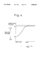
- FIG. 4 is a graph showing a typical change in the smoothed pressure value of the canister after a purge operation of the canister is stopped;
- FIG. 5 is a flowchart illustrating an example of a smoothing processing of the pressure values
- FIG. 6 is a flowchart illustrating an example of an operation for setting the degree of smoothing of the fluctuations of the pressure values
- FIG. 7 is a drawing schematically illustrating a typical construction of a rollover valve in the fuel tank.
- FIG. 8 is a flowchart illustrating another example of the operation for setting the degree of smoothing of the fluctuations of the pressure values.
- FIG. 1 schematically illustrates an embodiment of the evaporative emission control system of the present invention when applied to an automobile engine.
- reference numeral 1 designates an internal combustion engine for an automobile
- numeral 2 designates an intake air passage of the engine
- numeral 3 designates an air-cleaner disposed in the intake air passage 2.
- a throttle valve 6 which takes a degree of opening determined by the amount of depression of an accelerator pedal (not shown in the drawing) by the driver of the automobile, is disposed.
- a fuel injection valve 7 which injects pressurized fuel from a fuel supply pump 70 to the intake ports of the respective cylinders of the engine 1, is disposed in the intake air passage 2.
- Fuel in the fuel tank 11 is pressurized by the fuel pump 70 and is supplied to the fuel injection valve 7 through a feed pipe 71.
- a pressure regulator which adjusts the pressure of the fuel supplied to the fuel injection valve 7 to a constant value is provided on the fuel feed pipe 71.
- the part of the fuel supplied to the fuel injection valve 7 which is not injected to the intake port of the cylinders is returned to the fuel tank 11 through a return pipe 73.
- Numeral 20 in FIG. 1 denotes a control circuit of the engine 1.
- the control circuit 20 may, for example, consist of a microcomputer of conventional type which comprises a ROM 22, a RAM 23, a CPU 24, an input port 25 and an output port 26 connected by a bi-directional bus 21.
- the control circuit 20 performs basic engine control such as fuel injection control and ignition timing control of the engine 1. Further, in this embodiment, the control circuit 20 performs detection of failure in the evaporative emission control system as explained later in detail.
- parameters representing operating conditions of the engine such as the engine speed, the flow rate of intake air supplied to the engine, the temperature of the cooling water of the engine are fed to the input port 25 of the control circuit 20 from the corresponding sensors via an A/D (analogue-to-digital) converter (not shown in the drawing).
- an output signal from a pressure sensor 30 is also fed to the input port 25 via an A/D converter.
- the pressure sensor 30 will be explained later.
- Numeral 10 in FIG. 1 denotes a canister for adsorbing fuel vapor evaporated from the fuel in the fuel tank 11.
- the canister 10 is connected to the fuel tank 11 by a fuel vapor passage 12 at the portion above the fuel level therein.
- the canister 10 is also connected to the intake air passage 2 at the portion downstream of the throttle valve 6 by a purge gas passage 14.
- Numeral 15 in FIG. 1 shows a purge control valve.
- the purge control valve 15 is equipped with an actuator 15a of appropriate type, such as a solenoid actuator or vacuum actuator.
- the actuator 15a actuates in response to a drive signal supplied from the control circuit 20 and opens the purge control valve 15 under a predetermined operating condition of the engine 1 to connect the canister 10 and the portion of the intake air passage 2 downstream of the throttle valve 6, thereby generating a purge gas flow through the canister 10.
- FIG. 2 illustrates the construction of the canister 10 in FIG. 1.
- the canister 10 comprises a housing 10a and a fuel vapor adsorbent 13, such as active carbon, filled in the housing 10a.
- a fuel vapor adsorbent 13 such as active carbon
- an internal pressure control valve 16 and an atmospheric valve 18 are provided to control the operation for adsorption of fuel vapor to the adsorbent 13 and releasing of the adsorbed fuel vapor from the adsorbent (i.e., purging of fuel vapor from the adsorbent 13).
- the operation for adsorption and purging of fuel vapor will be explained later.
- a separator plate 10b is disposed at the position between the internal pressure control valve 16 and the atmospheric valve 18.
- the adsorbent 13 in the housing 10a is divided by the separator plate 10b into two sections, i.e., the section 13a on the internal pressure control valve 16 side and the section 13b on the atmospheric valve 18 side.
- an aperture 10c which communicates the section 13a and the section 13b is provided on the opposite end thereof from the valves 16 and 18.
- the internal pressure control valve 16 comprises a port 16a communicating inside of the housing 10a and a diaphragm 16b.
- the diaphragm 16b is urged by the spring 16c to the port 16a so that the port 16a is closed by the diaphragm 16b.
- a pressure chamber 16d is formed on the spring 16c side of the diaphragm and communicates to the atmosphere.
- another pressure chamber 16f which communicates to the fuel tank 11a via the fuel vapor passage 12 is formed on the side of the diaphragm 16b opposite to the pressure chamber 16d.
- the pressure chamber 16f communicates with the inside of the housing 10a via a pressure equalizing valve 17 having a check ball 17a and spring 17b.
- the atmospheric valve 18 has a similar construction to that of the internal pressure control valve 16 and comprises a port 18a communicating to the inside of the housing 10a, a diaphragm 18b and a spring 18c.
- a pressure chamber 18d formed on the spring 18c side of the diaphragm 18b is connected to the section 13a, which is formed on the internal pressure control valve 16 side in the housing 10a, through a pipe 18g.
- a pressure chamber 18f formed on the side of the diaphragm 18b opposite to the pressure chamber 18d is connected to the air-cleaner 3 via a pipe 18e.
- the section 13b of the adsorbent 13 inside the housing 10a is connected to the atmosphere via a relief valve 19 comprising a check ball 19a and a spring 19b.
- the purge gas passage 14 stated before is connected to the section 13a of the adsorbent 13 which is located on the internal pressure control valve 16 side in the housing 10a.
- FIG. 2 when the fuel temperature rises with the internal purge control valve 15 being closed, the pressure in the fuel tank 11 increases due to evaporation of fuel inside the fuel tank 11. Since fuel vapor volume above the fuel level in the fuel tank 11 communicates to the pressure chamber 16f in the internal pressure control valve 16, the pressure in the pressure chamber 16f also increases due to a pressure rise in the fuel tank 11. Further, atmospheric pressure is introduced to the pressure chamber 16d which is on the side of the diaphragm 16b opposite to the pressure chamber 16f, through the port 16e.
- the fuel tank 11 communicates with the atmosphere through the canister 10, and the pressure in the fuel tank 11 is kept lower than or equal to the above mentioned predetermined pressure.
- the purge control valve 15 is opened. This causes the section 13a in the housing 10a to communicate with the intake air passage 2 at the portion downstream of the throttle valve 6 through the purge gas passage 14. When this occurs, a negative pressure in the intake air passage 2 downstream of the throttle valve 6 is introduced to the housing 10a and lowers the pressure inside the housing 10a. Since the pressure chamber 18d in the atmospheric valve 18 is connected to the section 13a inside the housing through the pipe 18g, the pressure in the pressure chamber 18d becomes lower than the atmospheric pressure.
- the diaphragm 18b is pushed by the pressure in the pressure chamber 18f which is connected to the air-cleaner 3 by the pipe 18e to open the port 18a against the urging force of the spring 18c.
- clean air from the air-cleaner 3 flows into the section 13b in the housing 10a through the pipe 19e and the port 18a.
- This clean air flows through the sections 13b and 13a of the adsorbent 13, then, flows into the intake air passage 2 via the purge gas passage 14.
- the fuel vapor adsorbed by the adsorbent 13 is released (purged) from the adsorbent, thereby the adsorbent 13 is prevented from being saturated with fuel vapor.
- Fuel vapor released from the adsorbent 13 mixes with the purge air from the air-cleaner 3, and forms a mixture of air and fuel vapor (i.e., purge gas). Since this purge gas is fed to the engine 1 and burned in the combustion chamber thereof, emission of the evaporated fuel from the fuel tank 11 is prevented.
- the spring 18c of the atmospheric valve 18 is set in such a manner that the atmospheric valve 18 opens when the pressure inside the canister 10 becomes lower than the atmospheric pressure by, for example, about 1.5 KPa (150 mmH 2 O) to introduce clean air from the air-cleaner 3 into the canister 10.
- the pressure in the fuel tank 11 decreases.
- the equalizing valve 17 is opened by the pressure in the canister 10 and the canister 10 is connected to the fuel tank 11 by the fuel vapor passage 12. Therefore, when the pressure in the fuel tank 11 becomes lower than the atmospheric pressure, the pressure in the canister housing 10a also becomes lower than the atmospheric pressure, thereby the atmospheric valve 18 opens. This causes the clean air from the air-cleaner 3 to be introduced into the canister housing 10a, and flows into the fuel tank 11 through the adsorbent 13, equalizing valve 17 and the fuel vapor passage 12.
- the spring 17b in this embodiment is set in such a manner that the equalizing valve 17 opens when the pressure in the fuel tank 11 becomes lower than the pressure in the canister housing 10a by, for example, about 0.5 KPa (50 mmH 2 O).
- the adsorbent 13 in the canister 10 adsorbs and releases fuel vapor in accordance with the opening and closing of the purge control valve 15 to prevent emission of fuel vapor to the atmosphere.
- emission of fuel vapor may occur.
- leakage from the fuel tank 11 or canister housing 10a occurs, fuel vapor is released to the atmosphere.
- a pressure sensor 30 (FIG. 1) is provided in order to detect such a failure.
- the pressure sensor 30 generates a voltage signal corresponding to the difference between the pressure to be detected and the atmospheric pressure, and this analogue voltage signal is fed to the input port 25 of the control circuit 20 after it is converted to a digital signal by an A/D converter (not shown).
- the pressure sensor 30 is connected to the fuel vapor passage 12 and the portion of the purge gas passage 14 between the canister 10 and the purge control valve 15 via a three-way switching valve 31 so that it can detect the pressure in the fuel vapor passage 12 (i.e., the pressure in the fuel tank 11) and the pressure in the purge gas passage 14 (i.e., the pressure in the canister housing 10a) selectively by switching the three-way switching valve 31.
- Numeral 31a in FIG. 1 shows an actuator of an appropriate type, such as a solenoid actuator or a vacuum actuator.
- the actuator 31a is connected to the output port 26 of the control circuit 20 via a driving circuit (not shown) and switches the three-way switching valve 31 in response to a driving signal from the control circuit 20.
- failure in the evaporative emission control system is detected by the method explained hereinafter.
- leakage from the fuel tank 11 is detected by monitoring the change in the pressure in the fuel tank 11 after the engine has started.
- the pressure in the fuel tank is low because of the low fuel temperature in the fuel tank.
- the pressure in the fuel tank at the engine start is higher than the atmospheric pressure due to the high temperature of fuel in the tank 11.
- the pressure in the tank 11 is kept lower than the pressure setting of the internal pressure control valve 16 (for example, 1 KPa) since if the pressure in the tank 11 exceeds this pressure, the internal pressure control valve 16 opens to relieve the pressure in the tank 11 to the canister 10.
- the level of fuel in the fuel tank 11 goes down since the fuel is pumped from the fuel tank by the fuel pump 70. Therefore, the pressure in the fuel tank 11 decreases due to a decrease in the fuel level in the tank, and when a certain time has elapsed after the engine starts, the pressure in the fuel tank 11 becomes lower than the pressure when the engine started.
- FIG. 3 illustrates the change in the pressure in the fuel tank 11 after the engine starts.
- the solid line indicates the change in the pressure in the fuel tank 11 having no leakage after the engine 1 is started in a cold condition and the broken line indicates the change in the pressure in the fuel tank 11 having no leakage when the engine 1 is started in a hot condition.
- the pressure in the tank 11 goes down temporarily after the engine started and becomes lower than the atmospheric pressure due to a decrease in the fuel level, and the pressure in the tank 11 usually becomes lowest about 5 minutes after the engine has started.
- the pressure in the tank 11 gradually increases after it reaches the lowest pressure, and usually at about 20 minutes after the engine starts, the pressure reaches near the setting pressure of the internal pressure control valve 16.
- the pressure in the fuel tank 11 when the engine is started in a hot condition as is the case in which the engine is re-started after a short stop period, and if there is no leakage from the tank 11, the pressure in the fuel tank 11 is higher than the atmospheric pressure since the temperature of fuel in the tank 11 is usually high. Therefore, as indicated by the broken line in FIG. 3, the pressure in the fuel tank 11 reaches the setting pressure of the internal pressure control valve 16 in a short time after the engine starts.
- the chain line in FIG. 3 indicates the change in the pressure in the fuel tank 11 after the engine starts in the case that the fuel tank 11 leaks. If the fuel tank leaks, since the inside of the tank 11 directly communicates to the atmosphere, the pressure in the fuel tank is maintained at a pressure near the atmospheric pressure regardless of the fuel temperature and fuel level in the tank. Therefore, if the pressure in the fuel tank stays near the atmospheric pressure, i.e., if the pressure in the fuel tank does not change more than a certain amount after the engine starts, it is considered that the fuel tank 11 leaks.
- the control circuit 20 switches the three-way switching valve 31 after the engine is started, to the position in which the pressure sensor 30 is connected to fuel vapor passage 12. Since the pressure in the fuel vapor passage 12 is the same as the pressure in the fuel tank 11, the pressure in the fuel tank 11 can be detected by the pressure sensor 30 by switching the three-way switching valve 31 to this position. Then, the control circuit 20 monitors the pressure in the fuel tank 11 until a predetermined time (for example, 5 to 20 minutes) has elapsed after the engine starts, and the control circuit 20 determines whether the pressure P in the fuel tank becomes higher than a first predetermined value P 1 or the pressure P becomes lower than a second predetermined value P 2 .
- a predetermined time for example, 5 to 20 minutes
- the first predetermined value P 1 and the second predetermined value P 2 are determined in accordance with the magnitude of leakage to be detected and, in this embodiment, the first predetermined value P 1 is set at a positive pressure around 0.3 KPa (30 mmH 2 O), and the second predetermined value P 2 is set at a negative pressure around -0.3 KPa (-30 mmH 2 O), as shown in FIG. 3. If the pressure P in the fuel tank does not become higher than P 1 nor lower than P 2 during the monitoring period, the control circuit 20 determines that a leak has occurred in the fuel tank 11, i.e., the evaporative emission control system has failed.
- the pressure P in the fuel tank 11 first decreases to a pressure lower than atmospheric pressure after the engine has started, then increases again to a pressure near the setting of the internal pressure control valve 16 in the case of a cold engine start, or increases to a pressure near the setting pressure of the internal pressure control valve 16 in a short time after the engine has started in the case of a hot engine start. Therefore, when the pressure P in the fuel tank does not become higher than P 1 (positive pressure) nor lower than P 2 (negative pressure), it is considered that a leakage has occurred in the fuel tank 11.
- P 1 positive pressure
- P 2 negative pressure
- leakage from the canister 10 is detected using the change in the pressure in the canister 10 when the purge control valve 15 is opened and closed.
- the purge control valve When the purge control valve is opened during the operation of the engine, since a negative pressure in the intake air passage 2 downstream of the throttle valve 6 is introduced into the canister housing 10a via the purge gas passage 14, the pressure in the canister housing 10a becomes lower than the atmospheric pressure. In this case, if the purge control valve 15 is closed again (i.e., if a purge cut operation is performed), the pressure in the canister 10 is maintained at a negative pressure near the setting pressure of the atmospheric valve 18.
- FIG. 4 schematically illustrates the change in the pressure in the canister 10 after the purge control valve 15 is closed.
- the solid line represents the change in the pressure in the canister when there is no leakage in the canister 10
- the broken line represents the same when the canister 10 leaks. Since the volume in the canister housing 10a is relatively small, if the canister 10 leaks, the pressure in the canister increases rapidly after the purge control valve 15 is closed, as shown by the solid line in FIG. 4.
- the control circuit 20 closes the purge control valve 15 during the purging operation, and monitors the pressure in the canister 10 until a predetermined time has elapsed after closing the purge control valve 15. If the pressure in the canister 10 increases more than a predetermined value during the monitoring period, the control circuit 20 determines that the canister 10 is leaking. Namely, the control circuit 20 opens the purge control valve 15 by actuating the actuator 15a of the purge control valve 15 when predetermined conditions are satisfied after the engine 1 has started.
- the predetermined conditions mentioned above are, for example, the cooling water temperature of the engine 1 is higher than a predetermined value (i.e., the engine warming up is completed), the air-fuel ratio of the engine is feedback controlled (i.e., the operating air-fuel ratio of the engine 1 is not affected by the introduction of the purge gas from the canister), the flow rate of the intake air is more than a predetermined value, and a fuel cut operation is not being performed.
- the control circuit 20 performs the purging operation by opening the purge control valve 15.
- the control circuit 20 switches the three-way switching valve 31 to the position in which the pressure sensor 30 is connected to the purge gas passage 14. Since the pressure in the purge gas passage 14 is the same as the pressure in the canister 10, the pressure in the canister 10 is detected by the pressure sensor 30 when the three-way switching valve is switched to this position. Then, the control circuit 20 temporarily closes the purge control valve 15, and detects the pressure P 3 in the canister 10 when the purge control valve 15 is closed and the pressure P 4 in the canister 10 when a predetermined time T has elapsed after the valve 15 is closed.
- the control circuit 20 determines that the canister 10 is leaking.
- the predetermined time T and the value ⁇ P 0 are determined in accordance with the magnitude of leakage to be detected, and in this embodiment, T is set at around 1 second and ⁇ P 0 , is set at around 0.3 KPa (30 mmH 2 O).
- the failure of the canister 10 and the fuel tank 11 is detected in accordance with the change in the pressure during a predetermined time period, and the threshold value for the failure detection is relatively small in both cases.
- the pressure value detected by the pressure sensor 30 fluctuates due to the engine vibration and the movement of fuel in the fuel tank. Therefore, if the failure detection is performed based on the raw pressure values detected by the pressure sensor 30, error in the detection occurs.
- smoothed pressure values instead of the raw pressure values detected by the pressure sensor 30, are used for detecting failures in the system in this embodiment.
- the smoothed pressure values are obtained by smoothing fluctuations of the raw pressure values by the method explained below.
- FIG. 5 is a flowchart showing a smoothing processing used for obtaining the smoothed pressure values in this embodiment.
- This routine is processed by the control circuit 20 at predetermined intervals (for example, every 0.1 sec).
- the raw pressure value P detected by the pressure sensor is A/D converted at step 501. Then, at step 503, the smoothed pressure value P N is calculated by the following formula.
- P N (i-1) is the smoothed pressure value calculated when the routine is last executed
- K is a weighting factor which represents degree of smoothing.
- the smoothed pressure value P N calculated at step 503 is stored in the RAM 23 in the control circuit 20 at step 505. Then, the value of P N (i-1) is renewed at step 507 to prepare next execution of the routine before the routine terminates this time.
- the smoothed pressure value P N is calculated as a weighted mean of the smoothed pressure value P N (i-1) when the routine is last executed and the raw pressure value P detected by the pressure sensor 30 using a weighting factor K.
- the degree of smoothing of the fluctuations can be adjusted by changing the value of the weighting factor K. For example, if the weighting factor K is set at a larger value, the degree of smoothing of the fluctuations becomes larger, i.e., the smoothed pressure value P N becomes less affected by fluctuations of the raw pressure values and the response of P N to changes in the raw pressure value becomes slow.
- the weighting factor K used in the smoothing calculation is set at a large value, the change in the smoothed pressure value P N of the canister 10 becomes excessively slow.
- the change in the smoothed pressure value P N does not follow the pressure change in the canister 10 and the change in the smoothed pressure value does not reach the above-noted predetermined value during the monitoring period even when the actual pressure in the canister changes more than the predetermined value.
- the weighting factor K is set at a large value, errors may occur in which a failed canister is determined to be normal.
- the fluctuations of the pressure in the fuel tank 11 are mainly caused by the movement of fuel in the fuel tank and blockage of the fuel vapor passage 12 by a rollover valve as explained later, and the period and the amplitude of the fluctuations are relatively large.
- the pressure in the fuel tank must be monitored for a time period much longer than that required for detecting failures of the canister (for example, 5 to 20 minutes).
- the weighting factor K is set at a small value, the calculated smoothed pressure value P N becomes too sensitive to fluctuations of the pressure in the fuel tank. This causes P N to follow the fluctuations of the raw pressure in the fuel tank, i.e., the smoothed pressure value P N itself fluctuates.
- the value of P N exceeds the above-noted predetermined values P 1 or P 2 due to its fluctuations even if the actual pressure stays near the atmospheric pressure.
- an error may occur in which a failed fuel tank is determined to be normal when the weighting factor K is set at a small value.
- the weighting factor K in the calculation of the smoothed pressure value P N in the fuel tank must be set at a value larger than that in the calculation of the smoothed value P N in the canister, in order to detect failures correctly in both cases.
- the weighting factor K is set at different values in the calculations of the smoothing pressure values of the canister and the smoothing pressure values of the fuel tank.
- FIG. 6 shows a flowchart illustrating the operation for setting the weighting factor K in the calculation of the smoothing pressure values shown in FIG. 5. This routine is performed by the control circuit 20 at predetermined intervals.
- K the weighting factor K in the calculation of the smoothed pressure value P N of the fuel tank 11 is always set at a larger value than the same of the canister 10 when the routine in FIG. 5 is executed, thereby the error as explained above is eliminated from the detection of failure in the evaporative emission control system.
- the amplitude of the pressure fluctuations of the fuel tank changes in accordance with the amount of fuel (fuel level) in the fuel tank.
- fuel level in the tank is high, since the volume in the tank above the fuel level is small, fluctuation of the pressure becomes large even if the movement of fuel in the tank is small. Further, when the fuel level is high, sometimes even larger fluctuations of the pressure are caused by the operation of a rollover valve which is provided in the fuel tank to prevent fuel from spilling from the tank when the automobile is overturned.
- FIG. 7 schematically illustrates a typical configuration of the rollover valve in the fuel tank.
- reference numeral 71 denotes a port of the fuel tank II to which the fuel vapor passage 12 is connected
- numeral 70 denotes a rollover valve disposed at the port 71.
- the rollover valve 70 consists of a cage 72 surrounding the port 71 and a float 73 disposed therein.
- a plurality of through holes 72a are provided on the side wall of the cage 72 to communicate the fuel vapor passage 12 to the fuel vapor volume formed in the fuel tank above the fuel level.
- float 73 is pulled to the bottom of the cage 72 by gravity, thereby the port 71 is not blocked by the float 73.
- the float 73 is urged to the port 71 by fuel and blocks the port 71, thereby the spillage of the fuel from the port 71 is prevented.
- the rollover valve 70 is provided to block the port 71 in case of overturning of the automobile, the rollover valve sometimes blocks the port 71 due to the movement of the fuel when the fuel level in the tank is high.
- the pressure in the fuel vapor passage 12 largely changes, and the pressure detected by the pressure sensor 30 fluctuates largely in accordance with the movement of the float 73 (i.e., the movement of the fuel in the tank).
- the holes 72a on the cage 72 are sometimes blocked by the splash of fuel when the fuel level in the tank is high.
- the pressure detected by the sensor 30 also largely fluctuates. These types of fluctuations occur more frequently when the fuel level in the tank is higher, i.e. as the amount of the fuel in the tank is larger.
- the smoothed pressure value P N in the fuel tank when the amount of fuel in the tank is large is calculated using the weighting factor K suitable for a low fuel level condition in the tank, an error may occur due to insufficient smoothing of fluctuations.
- the weighting factor K suitable for a high fuel level condition in the tank is used when the amount of fuel in the tank is small, an error may also occur since the response of the smoothed pressure value P N to the change in the pressure in the tank become too slow.
- the value of the weighting factor K used in the calculation of the smoothed pressure value P N of the fuel tank is changed in accordance with the amount of fuel in the fuel tank in this embodiment, to thereby obtain a suitable smoothed pressure value in accordance with the fuel amount in the fuel tank.
- FIG. 8 shows a flowchart illustrating the operation for setting the weighting factor K at a suitable value in accordance with the amount of fuel in the fuel tank. This routine is executed by the control circuit 20 at predetermined intervals.
- the amount of the fuel may be detected by means of an acoustic type level sensor disposed on the top of the fuel tank.
- the acoustic type level sensor detects the fuel level by emitting an acoustic signal and receiving the signal reflected by the fuel surface.
- the fuel level i.e., the amount of fuel in the fuel tank is directly detected.
- the amount of the fuel in the tank may be determined indirectly by calculating the fuel consumption. For example, when fluctuation of the pressure in the fuel tank is very large, it is considered that the fuel tank is full.
- the amount of the fuel in the tank at an arbitrary time point is obtained by subtracting the total amount of fuel consumed by the engine since the tank was last full, from the amount of the fuel when the tank is full.
- the total amount of consumed fuel may be obtained by calculating a cumulative value of the engine load (or, cumulating a value obtained by multiplying the engine load by the engine operating time).
- the amount of fuel in the fuel tank is obtained using one or more of the methods explained above.
- the predetermined value used at step 805 varies in accordance with the size and the configuration of the fuel tank 11. Therefore, it is preferable to determine this value by experiment using the actual fuel tank.
- the weighting factor K used for calculating the smoothed pressure value P N of the fuel tank 11 is set larger as the amount of fuel in the tank becomes larger, a suitable smoothed pressure value P N can be obtained regardless of the amount of the fuel in the fuel tank.
- the value of the weighting factor K is changed in accordance with whether the amount of fuel in the tank is larger than the predetermined value in the above embodiment, the value of the weighting factor K may be changed continuously according to the change in the amount of the fuel in the fuel tank. Further, though a single pressure sensor with a three-way switching valve is used to detect both the pressure in the canister and the pressure in the fuel tank in the above embodiments, the present invention can be applied to the case in which separate pressure sensors are used for detecting the pressures in the canister and the fuel tank.
- the smoothed pressure value calculated immediately after the three-way switching valve 31 is switched is affected by the smoothed pressure value calculated before the switching of the valve 31. Therefore, it is preferable to start the failure detecting operation when a certain time has lapsed after the three-way switching valve 31 is switched.
- the value P N (i-1) may be replaced with a predetermined constant value (or, raw pressure value) when the routine in FIG. 5 is performed immediately after the switching of the valve 31.
- failure in the evaporative emission control system can be detected precisely by using the smoothed pressure value which is obtained by smoothing the fluctuations of the pressures in the canister and the fuel tank according to the characteristics of the fluctuations.
Landscapes
- Engineering & Computer Science (AREA)
- Chemical & Material Sciences (AREA)
- Combustion & Propulsion (AREA)
- Mechanical Engineering (AREA)
- General Engineering & Computer Science (AREA)
- Supplying Secondary Fuel Or The Like To Fuel, Air Or Fuel-Air Mixtures (AREA)
Applications Claiming Priority (2)
| Application Number | Priority Date | Filing Date | Title |
|---|---|---|---|
| JP07038467A JP3139318B2 (ja) | 1995-02-27 | 1995-02-27 | エバポパージシステムの故障診断装置 |
| JP7-038467 | 1995-02-27 |
Publications (1)
| Publication Number | Publication Date |
|---|---|
| US5590634A true US5590634A (en) | 1997-01-07 |
Family
ID=12526058
Family Applications (1)
| Application Number | Title | Priority Date | Filing Date |
|---|---|---|---|
| US08/605,485 Expired - Lifetime US5590634A (en) | 1995-02-27 | 1996-02-26 | Evaporative emission control system for an internal combustion engine |
Country Status (4)
| Country | Link |
|---|---|
| US (1) | US5590634A (de) |
| EP (1) | EP0733793B1 (de) |
| JP (1) | JP3139318B2 (de) |
| DE (1) | DE69600468T2 (de) |
Cited By (11)
| Publication number | Priority date | Publication date | Assignee | Title |
|---|---|---|---|---|
| US5726354A (en) * | 1995-07-31 | 1998-03-10 | Toyota Jidosha Kabushiki Kaisha | Testing method for fuel vapor treating apparatus |
| US5845625A (en) * | 1996-07-19 | 1998-12-08 | Toyota Jidosha Kabushiki Kaisha | Defect diagnosing apparatus of evaporation purge system |
| US5878729A (en) * | 1998-05-06 | 1999-03-09 | General Motors Corporation | Air control valve assembly for fuel evaporative emission storage canister |
| US5878728A (en) * | 1996-06-11 | 1999-03-09 | Toyota Jidosha Kabushiki Kaisha | Failure diagnosis apparatus for evaporative purge system |
| US6220229B1 (en) * | 1998-04-20 | 2001-04-24 | Nissan Motor Co., Ltd. | Apparatus for detecting evaporative emission control system leak |
| US6488015B2 (en) * | 2001-04-24 | 2002-12-03 | Nissan Motor, Co., Ltd. | Refueling system |
| US20060142931A1 (en) * | 2004-12-23 | 2006-06-29 | Cho Joon K | Method for determining malfunction of pressure sensor |
| US7121265B2 (en) * | 2001-09-25 | 2006-10-17 | Robert Bosch Gmbh | Method for operating a fuel supply system for an internal combustion engine in a motor vehicle |
| US20100146941A1 (en) * | 2007-04-19 | 2010-06-17 | Volvo Lastvagnar Ab | Method and arrangement for monitoring of injector |
| US20140174411A1 (en) * | 2012-12-26 | 2014-06-26 | Mitsubishi Jidosha Kogyo Kabushiki Kaisha | Apparatus for suppressing fuel evaporative gas emission |
| US10487765B2 (en) * | 2017-08-04 | 2019-11-26 | Mitsubishi Jidosha Kogyo Kabushiki Kaisha | Failure detection apparatus for fuel systems of engine |
Families Citing this family (2)
| Publication number | Priority date | Publication date | Assignee | Title |
|---|---|---|---|---|
| DE10163923A1 (de) * | 2001-12-22 | 2003-07-03 | Mahle Filtersysteme Gmbh | Be- und Entlüftungseinrichtung des Kraftstoff-Tankes eines Verbrennungsmotors |
| CN111103148B (zh) * | 2019-12-18 | 2021-11-30 | 中国第一汽车股份有限公司 | 一种堵塞检测方法及车辆 |
Citations (6)
| Publication number | Priority date | Publication date | Assignee | Title |
|---|---|---|---|---|
| US5275144A (en) * | 1991-08-12 | 1994-01-04 | General Motors Corporation | Evaporative emission system diagnostic |
| US5363828A (en) * | 1992-07-22 | 1994-11-15 | Aisan Kogyo Kabushiki Kaisha | Fuel vapor processing apparatus of internal combustion engine |
| US5445015A (en) * | 1992-06-26 | 1995-08-29 | Mitsubishi Jidosha Kogyo Kabushiki Kaisha | Method and apparatus of detecting faults for fuels evaporative emission treatment system |
| US5448980A (en) * | 1992-12-17 | 1995-09-12 | Nissan Motor Co., Ltd. | Leak diagnosis system for evaporative emission control system |
| US5479905A (en) * | 1994-01-31 | 1996-01-02 | Fuji Jukogyo Kabushiki Kaisha | Fuel vapor control system and the method thereof |
| US5505182A (en) * | 1991-04-09 | 1996-04-09 | Robert Bosch Gmbh | Method and arrangement for checking a tank-venting system |
Family Cites Families (2)
| Publication number | Priority date | Publication date | Assignee | Title |
|---|---|---|---|---|
| JP2748723B2 (ja) * | 1991-06-10 | 1998-05-13 | トヨタ自動車株式会社 | エバポパージシステムの故障診断装置 |
| US5295472A (en) * | 1992-01-06 | 1994-03-22 | Toyota Jidosha Kabushiki Kaisha | Apparatus for detecting malfunction in evaporated fuel purge system used in internal combustion engine |
-
1995
- 1995-02-27 JP JP07038467A patent/JP3139318B2/ja not_active Expired - Lifetime
-
1996
- 1996-02-26 EP EP96102846A patent/EP0733793B1/de not_active Expired - Lifetime
- 1996-02-26 DE DE69600468T patent/DE69600468T2/de not_active Expired - Lifetime
- 1996-02-26 US US08/605,485 patent/US5590634A/en not_active Expired - Lifetime
Patent Citations (6)
| Publication number | Priority date | Publication date | Assignee | Title |
|---|---|---|---|---|
| US5505182A (en) * | 1991-04-09 | 1996-04-09 | Robert Bosch Gmbh | Method and arrangement for checking a tank-venting system |
| US5275144A (en) * | 1991-08-12 | 1994-01-04 | General Motors Corporation | Evaporative emission system diagnostic |
| US5445015A (en) * | 1992-06-26 | 1995-08-29 | Mitsubishi Jidosha Kogyo Kabushiki Kaisha | Method and apparatus of detecting faults for fuels evaporative emission treatment system |
| US5363828A (en) * | 1992-07-22 | 1994-11-15 | Aisan Kogyo Kabushiki Kaisha | Fuel vapor processing apparatus of internal combustion engine |
| US5448980A (en) * | 1992-12-17 | 1995-09-12 | Nissan Motor Co., Ltd. | Leak diagnosis system for evaporative emission control system |
| US5479905A (en) * | 1994-01-31 | 1996-01-02 | Fuji Jukogyo Kabushiki Kaisha | Fuel vapor control system and the method thereof |
Cited By (16)
| Publication number | Priority date | Publication date | Assignee | Title |
|---|---|---|---|---|
| US5726354A (en) * | 1995-07-31 | 1998-03-10 | Toyota Jidosha Kabushiki Kaisha | Testing method for fuel vapor treating apparatus |
| US5878728A (en) * | 1996-06-11 | 1999-03-09 | Toyota Jidosha Kabushiki Kaisha | Failure diagnosis apparatus for evaporative purge system |
| US5845625A (en) * | 1996-07-19 | 1998-12-08 | Toyota Jidosha Kabushiki Kaisha | Defect diagnosing apparatus of evaporation purge system |
| US6220229B1 (en) * | 1998-04-20 | 2001-04-24 | Nissan Motor Co., Ltd. | Apparatus for detecting evaporative emission control system leak |
| US5878729A (en) * | 1998-05-06 | 1999-03-09 | General Motors Corporation | Air control valve assembly for fuel evaporative emission storage canister |
| EP0955459A2 (de) | 1998-05-06 | 1999-11-10 | Delphi Technologies, Inc. | Luftsteuerventileinheit für Brennstoffdampfsammelbehälter |
| EP0955459A3 (de) * | 1998-05-06 | 2000-05-31 | Delphi Technologies, Inc. | Luftsteuerventileinheit für Brennstoffdampfsammelbehälter |
| US6488015B2 (en) * | 2001-04-24 | 2002-12-03 | Nissan Motor, Co., Ltd. | Refueling system |
| US7121265B2 (en) * | 2001-09-25 | 2006-10-17 | Robert Bosch Gmbh | Method for operating a fuel supply system for an internal combustion engine in a motor vehicle |
| US20060142931A1 (en) * | 2004-12-23 | 2006-06-29 | Cho Joon K | Method for determining malfunction of pressure sensor |
| US7134413B2 (en) * | 2004-12-23 | 2006-11-14 | Hyundai Motor Company | Method for determining malfunction of pressure sensor |
| US20100146941A1 (en) * | 2007-04-19 | 2010-06-17 | Volvo Lastvagnar Ab | Method and arrangement for monitoring of injector |
| US8393141B2 (en) * | 2007-04-19 | 2013-03-12 | Volvo Lastvagnar Ab | Method and arrangement for monitoring of injector |
| US20140174411A1 (en) * | 2012-12-26 | 2014-06-26 | Mitsubishi Jidosha Kogyo Kabushiki Kaisha | Apparatus for suppressing fuel evaporative gas emission |
| US9664146B2 (en) * | 2012-12-26 | 2017-05-30 | Mitsubishi Jidosha Kogyo Kabushiki Kaisha | Apparatus for suppressing fuel evaporative gas emission |
| US10487765B2 (en) * | 2017-08-04 | 2019-11-26 | Mitsubishi Jidosha Kogyo Kabushiki Kaisha | Failure detection apparatus for fuel systems of engine |
Also Published As
| Publication number | Publication date |
|---|---|
| JPH08232782A (ja) | 1996-09-10 |
| EP0733793A2 (de) | 1996-09-25 |
| DE69600468D1 (de) | 1998-09-03 |
| EP0733793B1 (de) | 1998-07-29 |
| DE69600468T2 (de) | 1999-02-11 |
| JP3139318B2 (ja) | 2001-02-26 |
| EP0733793A3 (de) | 1997-08-20 |
Similar Documents
| Publication | Publication Date | Title |
|---|---|---|
| JP3317121B2 (ja) | エバポシステムおよびその診断方法 | |
| JP4607770B2 (ja) | 蒸発燃料処理装置 | |
| US7409947B2 (en) | Fuel vapor treatment apparatus | |
| US5297527A (en) | Diagnosing apparatus of evaporation fuel control system of vehicle | |
| US5590634A (en) | Evaporative emission control system for an internal combustion engine | |
| US7204239B2 (en) | Failure diagnostic apparatus and failure diagnostic method for in-tank canister system | |
| KR100293609B1 (ko) | 연료증산방지장치의고장진단장치 | |
| US5669362A (en) | Diagnostic device for an evaporative emission control system | |
| US5765540A (en) | Method of diagnosing an evaporative system | |
| JPH05125997A (ja) | 燃料蒸散防止装置用異常検出装置 | |
| JP4182650B2 (ja) | パージシステムの故障診断装置 | |
| JP3321943B2 (ja) | 燃料蒸散防止機構用異常検出装置 | |
| JP4172167B2 (ja) | 密閉タンクシステムの給油制御装置 | |
| JP2745991B2 (ja) | エバポパージシステムの故障診断装置 | |
| JP3139096B2 (ja) | 車両の蒸発燃料制御システムの診断装置 | |
| JP2699769B2 (ja) | エバポパージシステムの故障診断装置 | |
| JP2699774B2 (ja) | エバポパージシステムの故障診断装置 | |
| JPH06159157A (ja) | エバポパージシステムの故障診断装置 | |
| JP3158469B2 (ja) | 燃料蒸散防止装置用異常検出装置 | |
| JPH09303214A (ja) | エバポシステムの診断方法 | |
| JP2697524B2 (ja) | エバポパージシステムの故障診断装置 | |
| JP2699772B2 (ja) | エバポパージシステムの故障診断装置 | |
| JP3539285B2 (ja) | 蒸発燃料パージシステムの故障診断装置 | |
| JP2745984B2 (ja) | エバポパージシステムの故障診断装置 | |
| JPH07189831A (ja) | 燃料蒸発ガス抑止装置の診断装置 |
Legal Events
| Date | Code | Title | Description |
|---|---|---|---|
| AS | Assignment |
Owner name: TOYOTA JIDOSHA KABUSHIKI KAISHA, JAPAN Free format text: ASSIGNMENT OF ASSIGNORS INTEREST;ASSIGNOR:SHINOHARA, SUSUMU;REEL/FRAME:008164/0202 Effective date: 19960214 |
|
| FEPP | Fee payment procedure |
Free format text: PAYOR NUMBER ASSIGNED (ORIGINAL EVENT CODE: ASPN); ENTITY STATUS OF PATENT OWNER: LARGE ENTITY |
|
| STCF | Information on status: patent grant |
Free format text: PATENTED CASE |
|
| FPAY | Fee payment |
Year of fee payment: 4 |
|
| FPAY | Fee payment |
Year of fee payment: 8 |
|
| FPAY | Fee payment |
Year of fee payment: 12 |