EP0955459A2 - Luftsteuerventileinheit für Brennstoffdampfsammelbehälter - Google Patents
Luftsteuerventileinheit für Brennstoffdampfsammelbehälter Download PDFInfo
- Publication number
- EP0955459A2 EP0955459A2 EP99201327A EP99201327A EP0955459A2 EP 0955459 A2 EP0955459 A2 EP 0955459A2 EP 99201327 A EP99201327 A EP 99201327A EP 99201327 A EP99201327 A EP 99201327A EP 0955459 A2 EP0955459 A2 EP 0955459A2
- Authority
- EP
- European Patent Office
- Prior art keywords
- air
- canister
- valve
- atmosphere
- fuel
- Prior art date
- Legal status (The legal status is an assumption and is not a legal conclusion. Google has not performed a legal analysis and makes no representation as to the accuracy of the status listed.)
- Withdrawn
Links
- 239000000446 fuel Substances 0.000 title claims abstract description 46
- 230000000903 blocking effect Effects 0.000 claims abstract description 13
- 238000010926 purge Methods 0.000 claims description 38
- 239000002828 fuel tank Substances 0.000 claims description 17
- 238000007789 sealing Methods 0.000 claims description 6
- 230000006835 compression Effects 0.000 claims description 4
- 238000007906 compression Methods 0.000 claims description 4
- 238000012360 testing method Methods 0.000 abstract description 3
- OKTJSMMVPCPJKN-UHFFFAOYSA-N Carbon Chemical compound [C] OKTJSMMVPCPJKN-UHFFFAOYSA-N 0.000 description 22
- 229910052799 carbon Inorganic materials 0.000 description 16
- 238000000034 method Methods 0.000 description 6
- 238000013461 design Methods 0.000 description 5
- 239000000203 mixture Substances 0.000 description 5
- 239000007787 solid Substances 0.000 description 4
- 239000007788 liquid Substances 0.000 description 3
- 230000006698 induction Effects 0.000 description 2
- 230000000717 retained effect Effects 0.000 description 2
- 238000001179 sorption measurement Methods 0.000 description 2
- 241000272525 Anas platyrhynchos Species 0.000 description 1
- 238000004140 cleaning Methods 0.000 description 1
- 239000000356 contaminant Substances 0.000 description 1
- 238000011161 development Methods 0.000 description 1
- 238000001914 filtration Methods 0.000 description 1
- 230000003068 static effect Effects 0.000 description 1
- 238000011144 upstream manufacturing Methods 0.000 description 1
- 238000013022 venting Methods 0.000 description 1
Images



Classifications
-
- F—MECHANICAL ENGINEERING; LIGHTING; HEATING; WEAPONS; BLASTING
- F02—COMBUSTION ENGINES; HOT-GAS OR COMBUSTION-PRODUCT ENGINE PLANTS
- F02M—SUPPLYING COMBUSTION ENGINES IN GENERAL WITH COMBUSTIBLE MIXTURES OR CONSTITUENTS THEREOF
- F02M25/00—Engine-pertinent apparatus for adding non-fuel substances or small quantities of secondary fuel to combustion-air, main fuel or fuel-air mixture
- F02M25/08—Engine-pertinent apparatus for adding non-fuel substances or small quantities of secondary fuel to combustion-air, main fuel or fuel-air mixture adding fuel vapours drawn from engine fuel reservoir
- F02M25/0854—Details of the absorption canister
-
- F—MECHANICAL ENGINEERING; LIGHTING; HEATING; WEAPONS; BLASTING
- F02—COMBUSTION ENGINES; HOT-GAS OR COMBUSTION-PRODUCT ENGINE PLANTS
- F02M—SUPPLYING COMBUSTION ENGINES IN GENERAL WITH COMBUSTIBLE MIXTURES OR CONSTITUENTS THEREOF
- F02M25/00—Engine-pertinent apparatus for adding non-fuel substances or small quantities of secondary fuel to combustion-air, main fuel or fuel-air mixture
- F02M25/08—Engine-pertinent apparatus for adding non-fuel substances or small quantities of secondary fuel to combustion-air, main fuel or fuel-air mixture adding fuel vapours drawn from engine fuel reservoir
- F02M25/0809—Judging failure of purge control system
-
- F—MECHANICAL ENGINEERING; LIGHTING; HEATING; WEAPONS; BLASTING
- F02—COMBUSTION ENGINES; HOT-GAS OR COMBUSTION-PRODUCT ENGINE PLANTS
- F02M—SUPPLYING COMBUSTION ENGINES IN GENERAL WITH COMBUSTIBLE MIXTURES OR CONSTITUENTS THEREOF
- F02M25/00—Engine-pertinent apparatus for adding non-fuel substances or small quantities of secondary fuel to combustion-air, main fuel or fuel-air mixture
- F02M25/08—Engine-pertinent apparatus for adding non-fuel substances or small quantities of secondary fuel to combustion-air, main fuel or fuel-air mixture adding fuel vapours drawn from engine fuel reservoir
- F02M25/0836—Arrangement of valves controlling the admission of fuel vapour to an engine, e.g. valve being disposed between fuel tank or absorption canister and intake manifold
-
- B—PERFORMING OPERATIONS; TRANSPORTING
- B60—VEHICLES IN GENERAL
- B60K—ARRANGEMENT OR MOUNTING OF PROPULSION UNITS OR OF TRANSMISSIONS IN VEHICLES; ARRANGEMENT OR MOUNTING OF PLURAL DIVERSE PRIME-MOVERS IN VEHICLES; AUXILIARY DRIVES FOR VEHICLES; INSTRUMENTATION OR DASHBOARDS FOR VEHICLES; ARRANGEMENTS IN CONNECTION WITH COOLING, AIR INTAKE, GAS EXHAUST OR FUEL SUPPLY OF PROPULSION UNITS IN VEHICLES
- B60K15/00—Arrangement in connection with fuel supply of combustion engines or other fuel consuming energy converters, e.g. fuel cells; Mounting or construction of fuel tanks
- B60K15/03—Fuel tanks
- B60K15/035—Fuel tanks characterised by venting means
- B60K15/03504—Fuel tanks characterised by venting means adapted to avoid loss of fuel or fuel vapour, e.g. with vapour recovery systems
- B60K2015/03514—Fuel tanks characterised by venting means adapted to avoid loss of fuel or fuel vapour, e.g. with vapour recovery systems with vapor recovery means
Definitions
- This invention relates to automotive evaporative emission control system storage canisters in general, and specifically to a multi purpose air control valve for such a canister that combines an air inlet, air outlet, and diagnostic seal in one valve assembly.
- New American automobiles have incorporated fuel vapor storage canisters for some time now, originally designed simply to capture fuel vapor that would otherwise have vented from the tank while it was capped. Lately, the same canisters have also been used to capture fuel vapor displaced while the tank is uncapped and being filled with liquid fuel. Regardless of source, the stored fuel vapors are purged from the canister while the engine is running, typically by a vacuum (negative pressure air flow) applied to the canister, which pulls outside air in and through the activated carbon bed of the canister to desorb previously stored fuel vapors. The desorbed vapor is ultimately pulled into the engine air induction system and burned. The process is reversed when vapors enter the canister from the fuel tank, with clean air being expelled to the outside atmosphere.
- a vacuum negative pressure air flow
- Older canister designs generally incorporated a single, common port to atmosphere that provided both the outside air inlet for purge and the clean air exit for fuel adsorption. Such older designs also typically had the single atmospheric inlet/exit port located at one end of the canister, with the fuel vapor inlet and purge ports located at the opposite end. Newer canister designs often divide the activated carbon bed roughly in half with a flow division baffle, and locate the purge and fuel vapor ports on one side (vapor side) of one canister end, and the common atmospheric air inlet/exit port on the other side (air side) of the same end.
- An air inlet line 18e from air cleaner 3 connects to the air inlet port 18a across the diaphragm 18b.
- An oppositely spring loaded check valve 19a in the same housing opens directly to atmosphere.
- the spring 18c loading the diaphragm 18b down to block the air path to the air cleaner 3 must be stronger than the spring loaded check valve 19a, in order to allow air any break through vapor to pass only through valve 19a to atmosphere, and not to air cleaner 3. Consequently, during purge, in order to successfully pull the diaphragm 18b open, a separate pipe 18g must be provided to route some of the negative pressure from the purge port back behind the diaphragm 18b to overcome the spring 18c and allow air inlet flow to begin from the air cleaner 3. So, the strength of the spring 18c represents a compromise between certain purge air entry from the air cleaner and certain exit of venting air to the atmosphere only, without reverse flow back to the air cleaner.
- the level of negative pressure that can be applied and retained by the canister is effectively limited by the setting pressure of the diaphragm valve 18b, that is, by the strength of the spring 18c.
- a negative pressure greater than the strength of spring 18c since it is deliberately routed around and behind the diaphragm 18b to open it during the normal purge operation, will also overcome spring 18c and open it during diagnostic evacuation, and thereby pull outside air back into the canister. This leak will continue until the negative pressure falls low enough to allow the spring 18c to push the diaphragm 18b closed again.
- the invention provides an atmospheric air control valve for a vapor storage canister that separates the air inlet path from the air cleaner and the air exit path to atmosphere, but which is not limited, during diagnostic evacuation, by the strength of a spring loaded check valve. Instead, an actively operated blocking valve creates a solid canister seal during diagnostic evacuation, while still allowing for an efficient vapor purge and vapor fill process.
- a canister body carries both a purge and vapor inlet port on the top end of the vapor side of the canister.
- An air control valve housing opens through the top end of the air side of the canister.
- the housing has an air exit port direct to atmosphere, and an air inlet port routed from the air cleaner, both of which open to the canister carbon bed across a common lower passage.
- the air exit port is closed by a lightly spring loaded diaphragm, exposed to atmosphere on the spring side and to internal canister pressure on the seal side.
- the air inlet port is closed and opened by a free swinging, light flapper door, which allows free air flow in from the air cleaner, but quickly blocks any reverse flow from the canister to the air cleaner.
- a solenoid operated plunger Interposed between the flapper door and the common passage is a solenoid operated plunger, capable of solidly blocking the air inlet path to the air cleaner independently of the flapper door, but which is normally open.
- the on board control system closes the normally open solenoid plunger, solidly sealing any possible outside air inflow from the air cleaner.
- the other possible leak path is passively closed by the spring loaded diaphragm, and evacuation only assists in that seal.
- the canister and fuel tank together can be evacuated to any desired level of negative pressure, because of the solid seal of the plunger, and the level of negative pressure not limited to just the setting pressure of a spring loaded check valve.
- a typical vehicle has a fuel tank 10 and a filtered air cleaner 12 upstream in the engine air induction system. Downstream of the air cleaner 12, a throttle body 14 provides a negative pressure to a purge line 16, opened and closed by a purge control valve 18.
- the control valve 18 is opened by the vehicle engine control system at such time as engine speed a fuel demand are sufficient to allow previously stored fuel vapors to be pulled off and burned.
- a canister indicated generally at 20, which has a hollow canister body 22 containing an activated carbon bed 24 that separates the fuel vapor component from a mixture of air and fuel vapors fed thereto from tank 10.
- the carbon bed 24 is divided by a flow baffle 26 into what may be generally denoted as an air side of the canister 20, on the right in Figure 1, and a vapor side on the left.
- This designation indicates that fuel vapor is both fed to, and pulled from, the fuel side of the canister body 22, while air is concurrently either expelled to atmosphere from, or pulled from atmosphere into, the air side.
- the fuel vapor and air sides of the canister body 22 are both ported at the top, or at one common end, whatever its orientation may be.
- the vapor side of canister body 22 has a conventional purge port 28 connected to the purge line 16, which is next to a fuel vapor port 30, but separated therefrom by a series of internal baffles.
- Fuel vapor port 30 is connected by a vapor line 32 that runs to the vapor dome of fuel tank 10. When closed, fuel tank 10 is sealed from atmosphere, but for the connection through vapor line 32 into canister body 22.
- vapor line 32 runs to the vapor dome of fuel tank 10.
- valve housing 36 which contains the other various cooperating components the valve assembly 34.
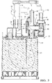
- Valve housing 36 is formed with an air exit port 38 open to atmosphere and an air inlet port 40 connected by an air inlet line 42 to the air cleaner 12. Both ports 38 and 40 open into a common lower passage 44 that is open to the carbon bed 24.
- the path between the carbon bed 24 and the exit port 38 is closed or opened by a passively acting check valve in the form of a spring loaded diaphragm 46.
- the rear, spring side of diaphragm 46 is vented to atmosphere, while the front, seal side is exposed to the internal pressure within housing 36 and canister body 22.
- the spring load on diaphragm 46 can be, and is, very light, just enough to keep it lightly loaded into the sealed position shown. Therefore, the diaphragm 46 can open whenever the canister internal pressure exceeds atmospheric pressure plus the small compression spring force, but will remain tightly closed whenever the internal pressure is even slightly under atmospheric.
- the path between the carbon bed 24 and the air inlet port 40 is closed or opened by a passively acting check valve in the form of a light, free swinging flapper door 48.
- Door 48 can swing shut easily to stop any flow from the carbon bed 24 through the air inlet port 40, but opens just as easily to allow flow in the other direction.
- an active or powered blocking valve in the form of a solenoid plunger 50 is mounted within housing 36, below the flapper door 48.
- Plunger 50 is normally open, but when powered, it blocks the path to the inlet port 40, independently of flapper door 48, for a purpose described below.
- Carbon bed 24 stores fuel vapors adsorbed whenever a mixture of vapor and air flows out of tank 10, since vapor line 32 is the only possible vent for such.
- the purge control valve 18 is opened, exposing the vapor side of canister body 22 to vacuum from the throttle body 14, through the purge line 16. Accordingly, a negative pressure appears at the opening of the purge port 28 to the top of the carbon bed 24, on the vapor side thereof.
- canister body 22 is sealed from atmosphere at all points, but for the air inlet port 40.
- the air exit port 38 is tightly sealed by the diaphragm 46, pushed closed by the combination of light spring pressure and negative internal pressure. While the fuel tank 10 is open to the interior of the canister body 22, tank 10 has no openings to atmosphere but for those in the canister body 22. Therefore, the interior of tank 10 will be evacuated, through vapor line 32, by the negative pressure within canister body 22 until that negative pressure is higher than the flow resistance through the carbon bed 24. Then, as illustrated by the arrows in Figure 2, flow from the tank 10 will stop, and outside air will instead be drawn in from air cleaner 12, through line 42 and inlet port 40, past the open flapper door 48 and normally open plunger 50 and through the common passage 44 into carbon bed 24.
- the outside air from air cleaner 12 will be pre filtered and relatively free of contaminants.
- the drawn in air flows down and through the carbon bed 24, around the baffle 26 in the U pattern shown, desorbing fuel vapors from the bed 24 along the way. Flowing air and entrained desorbed fuel vapors ultimately flow out purge port 28 and into the throttle body 14, where they are burned.
- the interior of canister body 22 is concurrently raised at least slightly above atmospheric pressure, which is more than sufficient to open the diaphragm 46 against its weak spring force, allowing flow out the exit port 38 to atmosphere.
- the flow out of exit port 38 will, under normal circumstances, be basically clean air, with all of the fuel vapor component having been adsorbed by the carbon bed 24.
- no break through fuel vapor will back flow through air inlet port 40 and into the air cleaner 12, because the flapper door 48 easily closes to prevent any such flow. There is no need to close the normally open plunger 50 to block such back flow to air cleaner 12.
- the on board self diagnostic program embedded in the vehicle's electronic controller energizes the solenoid plunger 50 to close it, solidly blocking the air inlet port 40 against any inflow of outside air.
- the only other possible outside air inflow point is the exit port 38, which is solidly closed by the diaphragm 46.
- purge control valve 18 is opened, and purge vacuum applied to purge port 28, drawing air and vapor out of both tank 10 and canister body 22 until the two together attain a desired level of negative pressure below atmospheric pressure.
- the negative pressure that can be applied is not limited by the setting pressure of any check valves, because of the solid closing of the plunger 50 that blocks inlet port 40 independently of the free swinging flapper door 48. Then, as determined by the diagnostic program, the purge valve 18 is closed, and the internal pressure of canister 22 and tank 10 is monitored at a set time interval later by any suitable pressure sensor in the system, not illustrated. If the negative pressure is sufficiently maintained for a sufficient time interval, it is determined that there are no significant external air leaks into the system.
- the diaphragm valve 46 could be replaced by a simpler type of spring loaded check valve, such as a ball, but the diaphragm design is preferable in that exposes a large working surface area to the canister internal pressure.
- the non spring loaded, one way flapper door 48 could be replaced by some other fast acting, freely opening and closing valve, such as a duck bill valve or the like. It need have no particular setting pressure, as a spring loaded check valve would have, since it is independently back up by the solenoid plunger 50.
- the plunger 50 could also be replaced by some other active, movable solid sealing member, which could actually be located in the line 42 and above the door 48, so long as it was normally open. However, it is very convenient to locate it within the same housing 36.
Landscapes
- Engineering & Computer Science (AREA)
- Chemical & Material Sciences (AREA)
- Combustion & Propulsion (AREA)
- Mechanical Engineering (AREA)
- General Engineering & Computer Science (AREA)
- Supplying Secondary Fuel Or The Like To Fuel, Air Or Fuel-Air Mixtures (AREA)
Applications Claiming Priority (2)
| Application Number | Priority Date | Filing Date | Title |
|---|---|---|---|
| US73419 | 1998-05-06 | ||
| US09/073,419 US5878729A (en) | 1998-05-06 | 1998-05-06 | Air control valve assembly for fuel evaporative emission storage canister |
Publications (2)
| Publication Number | Publication Date |
|---|---|
| EP0955459A2 true EP0955459A2 (de) | 1999-11-10 |
| EP0955459A3 EP0955459A3 (de) | 2000-05-31 |
Family
ID=22113591
Family Applications (1)
| Application Number | Title | Priority Date | Filing Date |
|---|---|---|---|
| EP99201327A Withdrawn EP0955459A3 (de) | 1998-05-06 | 1999-04-28 | Luftsteuerventileinheit für Brennstoffdampfsammelbehälter |
Country Status (3)
| Country | Link |
|---|---|
| US (1) | US5878729A (de) |
| EP (1) | EP0955459A3 (de) |
| JP (1) | JPH11343935A (de) |
Cited By (5)
| Publication number | Priority date | Publication date | Assignee | Title |
|---|---|---|---|---|
| DE10163923A1 (de) * | 2001-12-22 | 2003-07-03 | Mahle Filtersysteme Gmbh | Be- und Entlüftungseinrichtung des Kraftstoff-Tankes eines Verbrennungsmotors |
| US6692551B2 (en) | 2002-07-17 | 2004-02-17 | Delphi Technologies, Inc. | Air cleaner assembly and process |
| US6752859B2 (en) | 2002-10-02 | 2004-06-22 | Delphi Technologies, Inc. | Air cleaner assembly for reducing pollutants from being discharged into the atmosphere |
| US6959698B2 (en) | 2001-06-26 | 2005-11-01 | Toyo Roki Seizo Kabushiki Kaisha | Fuel treating canister |
| EP4419364A4 (de) * | 2021-10-18 | 2025-10-15 | Stant Usa Corp | Kohlenstoffkanister mit direkt verbundenem kraftstofftankabsperrventil |
Families Citing this family (36)
| Publication number | Priority date | Publication date | Assignee | Title |
|---|---|---|---|---|
| US20020002039A1 (en) * | 1998-06-12 | 2002-01-03 | Safi Qureshey | Network-enabled audio device |
| US6390073B1 (en) | 1999-08-26 | 2002-05-21 | Delphi Technologies, Inc. | Evaporative emission storage canister with integral filter and vent solenoid |
| US6450153B1 (en) * | 1999-11-19 | 2002-09-17 | Siemens Canada Limited | Integrated pressure management apparatus providing an on-board diagnostic |
| US6470908B1 (en) * | 1999-11-19 | 2002-10-29 | Siemens Canada Limited | Pressure operable device for an integrated pressure management apparatus |
| US6474314B1 (en) * | 1999-11-19 | 2002-11-05 | Siemens Canada Limited | Fuel system with intergrated pressure management |
| US6470861B1 (en) | 1999-11-19 | 2002-10-29 | Siemens Canada Limited | Fluid flow through an integrated pressure management apparatus |
| US6474313B1 (en) * | 1999-11-19 | 2002-11-05 | Siemens Canada Limited | Connection between an integrated pressure management apparatus and a vapor collection canister |
| US6453942B1 (en) * | 1999-11-19 | 2002-09-24 | Siemens Canada Limited | Housing for integrated pressure management apparatus |
| US6478045B1 (en) * | 1999-11-19 | 2002-11-12 | Siemens Canada Limited | Solenoid for an integrated pressure management apparatus |
| US6502560B1 (en) * | 1999-11-19 | 2003-01-07 | Siemens Canada Limited | Integrated pressure management apparatus having electronic control circuit |
| US6460566B1 (en) * | 1999-11-19 | 2002-10-08 | Siemens Canada Limited | Integrated pressure management system for a fuel system |
| EP1211408B1 (de) * | 2000-11-29 | 2007-03-21 | Siemens VDO Automotive Inc. | Entlüftungsventil mit einer Diagnosesöffnung |
| US6957206B2 (en) | 2001-04-19 | 2005-10-18 | Quantum Dynamics, Inc. | Computer system and method with adaptive N-level structures for automated generation of program solutions based on rules input by subject matter experts |
| US6959696B2 (en) * | 2002-04-12 | 2005-11-01 | Briggs & Stratton Corporation | Internal combustion engine evaporative emission control system |
| WO2004079467A1 (en) * | 2003-03-07 | 2004-09-16 | Siemens Vdo Automotive Inc. | An improved integrated pressure management apparatus |
| US7036359B2 (en) * | 2003-07-31 | 2006-05-02 | Aisan Kogyo Kabushiki Kaisha | Failure diagnostic system for fuel vapor processing apparatus |
| US7160361B2 (en) * | 2003-10-15 | 2007-01-09 | Delphi Technologies, Inc. | Evaporative emission treatment device |
| US7051717B2 (en) * | 2004-09-30 | 2006-05-30 | Delphi Technologies, Inc. | Evaporative emissions canister having an internal insert |
| US7086390B2 (en) * | 2004-11-05 | 2006-08-08 | Briggs & Stratton Corporation | Integrated fuel tank and vapor containment system |
| US7185640B2 (en) * | 2004-11-05 | 2007-03-06 | Briggs & Stratton Corporation | Integrated fuel tank and vapor containment system |
| JP4575115B2 (ja) * | 2004-11-15 | 2010-11-04 | 愛三工業株式会社 | キャニスタ |
| US7435289B2 (en) * | 2005-09-27 | 2008-10-14 | Briggs & Stratton Corporation | Integrated air cleaner and vapor containment system |
| US7451746B2 (en) * | 2005-12-23 | 2008-11-18 | Bellmore Daniel J | Canister assembly |
| US7281525B2 (en) * | 2006-02-27 | 2007-10-16 | Briggs & Stratton Corporation | Filter canister family |
| US20070256670A1 (en) * | 2006-05-05 | 2007-11-08 | Siemens Canada Limited | Integrated vacuum blocking valve |
| US7562651B2 (en) * | 2007-11-19 | 2009-07-21 | Mahle Technology, Inc. | Vapor canister having integrated evaporative emission purge actuation monitoring system having fresh air filter |
| KR100986062B1 (ko) * | 2008-04-07 | 2010-10-08 | 현대자동차주식회사 | 차량용 연료증발가스 재순환 장치 |
| KR101234639B1 (ko) * | 2010-09-29 | 2013-02-19 | 기아자동차주식회사 | 차량용 캐니스터 및 이를 구비한 연료 공급 장치 |
| JP5927979B2 (ja) * | 2012-02-23 | 2016-06-01 | 浜名湖電装株式会社 | 蒸発燃料パージ装置 |
| US9261057B2 (en) | 2012-11-07 | 2016-02-16 | Ford Global Technologies, Llc | Evaporative emission control |
| US9664127B2 (en) | 2014-06-24 | 2017-05-30 | Ford Global Technologies, Llc | System and methods for managing refueling vapors |
| DE102015201339B4 (de) | 2015-01-27 | 2017-11-30 | Volkswagen Ag | Vorrichtung mit einem Aktivkohlebehälter sowie ein Kraftfahrzeug mit einer solchen Vorrichtung |
| US9777678B2 (en) | 2015-02-02 | 2017-10-03 | Ford Global Technologies, Llc | Latchable valve and method for operation of the latchable valve |
| DE102016106920B4 (de) * | 2016-04-14 | 2022-09-29 | Dr. Ing. H.C. F. Porsche Aktiengesellschaft | Filtereinrichtung für ein Kraftfahrzeug |
| FR3069811B1 (fr) * | 2017-08-02 | 2019-08-02 | Sogefi Filtration | Dispositif de regulation de pression et son procede d'assemblage, pour un absorbeur de vapeurs de carburant |
| US12280656B2 (en) * | 2021-10-18 | 2025-04-22 | Stant Usa Corp. | Carbon canister with direct connect fuel tank isolation valve |
Citations (1)
| Publication number | Priority date | Publication date | Assignee | Title |
|---|---|---|---|---|
| US5590634A (en) | 1995-02-27 | 1997-01-07 | Toyota Jidosha Kabushiki Kaisha | Evaporative emission control system for an internal combustion engine |
Family Cites Families (18)
| Publication number | Priority date | Publication date | Assignee | Title |
|---|---|---|---|---|
| US4703736A (en) * | 1986-09-25 | 1987-11-03 | Chrysler Motors Corporation | Fuel vapor containment device |
| JPS6437813A (en) * | 1987-08-04 | 1989-02-08 | Toshiba Corp | Magnetic resonance imaging device |
| US5295472A (en) * | 1992-01-06 | 1994-03-22 | Toyota Jidosha Kabushiki Kaisha | Apparatus for detecting malfunction in evaporated fuel purge system used in internal combustion engine |
| JPH0712018A (ja) * | 1992-06-03 | 1995-01-17 | Nippon Soken Inc | 蒸発燃料処理装置 |
| US5383437A (en) * | 1992-12-23 | 1995-01-24 | Siemens Automotive Limited | Integrity confirmation of evaporative emission control system against leakage |
| EP0648637A1 (de) * | 1993-09-15 | 1995-04-19 | General Motors Corporation | Vorrichtung zum Einfangen von Dämpfen |
| JPH0725263U (ja) * | 1993-10-22 | 1995-05-12 | 本田技研工業株式会社 | 車輛用内燃機関の蒸発燃料処理装置 |
| DE4343654A1 (de) * | 1993-12-21 | 1995-06-22 | Bosch Gmbh Robert | Verfahren und Anlage zur Tankentlüftung |
| JP3319125B2 (ja) * | 1994-02-02 | 2002-08-26 | 株式会社デンソー | 内燃機関の蒸発燃料処理装置 |
| US5437257A (en) * | 1994-02-28 | 1995-08-01 | General Motors Corporation | Evaporative emission control system with vent valve |
| US5623911A (en) * | 1994-07-29 | 1997-04-29 | Toyota Jidosha Kabushiki Kaisha | Fuel vapor treating apparatus |
| JPH0861162A (ja) * | 1994-08-26 | 1996-03-05 | Aisan Ind Co Ltd | 自動車用蒸発燃料制御装置 |
| US5474050A (en) * | 1995-01-13 | 1995-12-12 | Siemens Electric Limited | Leak detection pump with integral vent seal |
| JP3198865B2 (ja) * | 1995-03-20 | 2001-08-13 | トヨタ自動車株式会社 | エバポパージシステムの故障診断装置 |
| US5509395A (en) * | 1995-03-31 | 1996-04-23 | Siemens Electric Limited | Canister purge flow regulator |
| JP3269751B2 (ja) * | 1995-06-22 | 2002-04-02 | 株式会社日立製作所 | 内燃機関制御装置 |
| JP3447858B2 (ja) * | 1995-08-04 | 2003-09-16 | 本田技研工業株式会社 | 車輌用内燃機関の蒸発燃料処理装置 |
| JP3516223B2 (ja) * | 1995-08-04 | 2004-04-05 | 本田技研工業株式会社 | 車輌用内燃機関の蒸発燃料処理装置 |
-
1998
- 1998-05-06 US US09/073,419 patent/US5878729A/en not_active Expired - Fee Related
-
1999
- 1999-04-28 EP EP99201327A patent/EP0955459A3/de not_active Withdrawn
- 1999-05-06 JP JP11125898A patent/JPH11343935A/ja active Pending
Patent Citations (1)
| Publication number | Priority date | Publication date | Assignee | Title |
|---|---|---|---|---|
| US5590634A (en) | 1995-02-27 | 1997-01-07 | Toyota Jidosha Kabushiki Kaisha | Evaporative emission control system for an internal combustion engine |
Cited By (7)
| Publication number | Priority date | Publication date | Assignee | Title |
|---|---|---|---|---|
| US6959698B2 (en) | 2001-06-26 | 2005-11-01 | Toyo Roki Seizo Kabushiki Kaisha | Fuel treating canister |
| DE10163923A1 (de) * | 2001-12-22 | 2003-07-03 | Mahle Filtersysteme Gmbh | Be- und Entlüftungseinrichtung des Kraftstoff-Tankes eines Verbrennungsmotors |
| US7163004B2 (en) | 2001-12-22 | 2007-01-16 | Mahle Filtersysteme Gmbh | Ventilation system for a fuel tank of an internal combustion engine |
| US6692551B2 (en) | 2002-07-17 | 2004-02-17 | Delphi Technologies, Inc. | Air cleaner assembly and process |
| US6752859B2 (en) | 2002-10-02 | 2004-06-22 | Delphi Technologies, Inc. | Air cleaner assembly for reducing pollutants from being discharged into the atmosphere |
| EP4419364A4 (de) * | 2021-10-18 | 2025-10-15 | Stant Usa Corp | Kohlenstoffkanister mit direkt verbundenem kraftstofftankabsperrventil |
| EP4419363A4 (de) * | 2021-10-18 | 2026-02-25 | Stant Usa Corp | Kohlenstoffkanister mit direkt verbundenem kraftstofftankabsperrventil |
Also Published As
| Publication number | Publication date |
|---|---|
| JPH11343935A (ja) | 1999-12-14 |
| US5878729A (en) | 1999-03-09 |
| EP0955459A3 (de) | 2000-05-31 |
Similar Documents
| Publication | Publication Date | Title |
|---|---|---|
| US5878729A (en) | Air control valve assembly for fuel evaporative emission storage canister | |
| JP3264129B2 (ja) | 内燃機関の蒸発燃料制御装置 | |
| JP3286348B2 (ja) | 内燃機関の蒸発ガス処理装置における異常検出装置 | |
| JP3320722B2 (ja) | 内燃機関の燃料タンクの排気装置 | |
| JP3391202B2 (ja) | 内燃機関の蒸発燃料制御装置 | |
| KR100986062B1 (ko) | 차량용 연료증발가스 재순환 장치 | |
| JP2004156496A (ja) | 内燃機関の蒸発燃料処理装置 | |
| JP3265985B2 (ja) | 燃料蒸気処理装置 | |
| JP3705398B2 (ja) | 内燃機関の蒸発燃料制御装置 | |
| US4783962A (en) | Brake booster vapor trap filter and fuel tank vapor trap canister vapor guard system | |
| JP3134704B2 (ja) | 内燃機関の蒸発燃料制御装置 | |
| JP3452103B2 (ja) | 蒸発燃料処理装置 | |
| JP2005054696A (ja) | 燃料蒸発ガス制御システムのリーク診断装置 | |
| JP3659005B2 (ja) | 燃料タンクの蒸発燃料処理装置 | |
| JPH11287160A (ja) | 蒸発燃料回収装置 | |
| JP4468769B2 (ja) | 蒸発燃料吸着装置 | |
| JPH0842407A (ja) | 蒸発燃料処理装置 | |
| JP3391209B2 (ja) | 内燃機関の蒸発燃料制御装置 | |
| JPH08232777A (ja) | 内燃機関の蒸発燃料制御装置 | |
| JP2005256624A (ja) | 内燃機関の蒸発燃料処理装置 | |
| JP2845079B2 (ja) | 内燃機関の蒸発燃料リーク診断装置 | |
| JPH1018921A (ja) | 内燃機関の蒸発燃料制御装置 | |
| JPH0861162A (ja) | 自動車用蒸発燃料制御装置 | |
| JP2000018112A (ja) | 蒸発燃料制御装置 | |
| JPH07151018A (ja) | 蒸発燃料の排出防止装置 |
Legal Events
| Date | Code | Title | Description |
|---|---|---|---|
| PUAI | Public reference made under article 153(3) epc to a published international application that has entered the european phase |
Free format text: ORIGINAL CODE: 0009012 |
|
| AK | Designated contracting states |
Kind code of ref document: A2 Designated state(s): DE FR GB IT |
|
| AX | Request for extension of the european patent |
Free format text: AL;LT;LV;MK;RO;SI |
|
| PUAL | Search report despatched |
Free format text: ORIGINAL CODE: 0009013 |
|
| AK | Designated contracting states |
Kind code of ref document: A3 Designated state(s): AT BE CH CY DE DK ES FI FR GB GR IE IT LI LU MC NL PT SE |
|
| AX | Request for extension of the european patent |
Free format text: AL;LT;LV;MK;RO;SI |
|
| 17P | Request for examination filed |
Effective date: 20001130 |
|
| AKX | Designation fees paid |
Free format text: DE FR GB IT |
|
| 17Q | First examination report despatched |
Effective date: 20010214 |
|
| STAA | Information on the status of an ep patent application or granted ep patent |
Free format text: STATUS: THE APPLICATION IS DEEMED TO BE WITHDRAWN |
|
| 18D | Application deemed to be withdrawn |
Effective date: 20010626 |