US5593462A - Method of manufacturing a multilayer electrochemical assembly comprising an electrolyte between two electrodes, and an assembly made thereby - Google Patents
Method of manufacturing a multilayer electrochemical assembly comprising an electrolyte between two electrodes, and an assembly made thereby Download PDFInfo
- Publication number
- US5593462A US5593462A US08/339,017 US33901794A US5593462A US 5593462 A US5593462 A US 5593462A US 33901794 A US33901794 A US 33901794A US 5593462 A US5593462 A US 5593462A
- Authority
- US
- United States
- Prior art keywords
- electrolyte
- film
- electrode
- extruded
- electrodes
- Prior art date
- Legal status (The legal status is an assumption and is not a legal conclusion. Google has not performed a legal analysis and makes no representation as to the accuracy of the status listed.)
- Expired - Lifetime
Links
Images



Classifications
-
- H—ELECTRICITY
- H01—ELECTRIC ELEMENTS
- H01M—PROCESSES OR MEANS, e.g. BATTERIES, FOR THE DIRECT CONVERSION OF CHEMICAL ENERGY INTO ELECTRICAL ENERGY
- H01M6/00—Primary cells; Manufacture thereof
- H01M6/14—Cells with non-aqueous electrolyte
- H01M6/18—Cells with non-aqueous electrolyte with solid electrolyte
- H01M6/181—Cells with non-aqueous electrolyte with solid electrolyte with polymeric electrolytes
-
- H—ELECTRICITY
- H01—ELECTRIC ELEMENTS
- H01M—PROCESSES OR MEANS, e.g. BATTERIES, FOR THE DIRECT CONVERSION OF CHEMICAL ENERGY INTO ELECTRICAL ENERGY
- H01M6/00—Primary cells; Manufacture thereof
- H01M6/04—Cells with aqueous electrolyte
- H01M6/06—Dry cells, i.e. cells wherein the electrolyte is rendered non-fluid
- H01M6/10—Dry cells, i.e. cells wherein the electrolyte is rendered non-fluid with wound or folded electrodes
-
- Y—GENERAL TAGGING OF NEW TECHNOLOGICAL DEVELOPMENTS; GENERAL TAGGING OF CROSS-SECTIONAL TECHNOLOGIES SPANNING OVER SEVERAL SECTIONS OF THE IPC; TECHNICAL SUBJECTS COVERED BY FORMER USPC CROSS-REFERENCE ART COLLECTIONS [XRACs] AND DIGESTS
- Y02—TECHNOLOGIES OR APPLICATIONS FOR MITIGATION OR ADAPTATION AGAINST CLIMATE CHANGE
- Y02E—REDUCTION OF GREENHOUSE GAS [GHG] EMISSIONS, RELATED TO ENERGY GENERATION, TRANSMISSION OR DISTRIBUTION
- Y02E60/00—Enabling technologies; Technologies with a potential or indirect contribution to GHG emissions mitigation
- Y02E60/10—Energy storage using batteries
-
- Y—GENERAL TAGGING OF NEW TECHNOLOGICAL DEVELOPMENTS; GENERAL TAGGING OF CROSS-SECTIONAL TECHNOLOGIES SPANNING OVER SEVERAL SECTIONS OF THE IPC; TECHNICAL SUBJECTS COVERED BY FORMER USPC CROSS-REFERENCE ART COLLECTIONS [XRACs] AND DIGESTS
- Y02—TECHNOLOGIES OR APPLICATIONS FOR MITIGATION OR ADAPTATION AGAINST CLIMATE CHANGE
- Y02P—CLIMATE CHANGE MITIGATION TECHNOLOGIES IN THE PRODUCTION OR PROCESSING OF GOODS
- Y02P70/00—Climate change mitigation technologies in the production process for final industrial or consumer products
- Y02P70/50—Manufacturing or production processes characterised by the final manufactured product
-
- Y—GENERAL TAGGING OF NEW TECHNOLOGICAL DEVELOPMENTS; GENERAL TAGGING OF CROSS-SECTIONAL TECHNOLOGIES SPANNING OVER SEVERAL SECTIONS OF THE IPC; TECHNICAL SUBJECTS COVERED BY FORMER USPC CROSS-REFERENCE ART COLLECTIONS [XRACs] AND DIGESTS
- Y10—TECHNICAL SUBJECTS COVERED BY FORMER USPC
- Y10T—TECHNICAL SUBJECTS COVERED BY FORMER US CLASSIFICATION
- Y10T29/00—Metal working
- Y10T29/49—Method of mechanical manufacture
- Y10T29/49002—Electrical device making
- Y10T29/49108—Electric battery cell making
- Y10T29/49112—Electric battery cell making including laminating of indefinite length material
-
- Y—GENERAL TAGGING OF NEW TECHNOLOGICAL DEVELOPMENTS; GENERAL TAGGING OF CROSS-SECTIONAL TECHNOLOGIES SPANNING OVER SEVERAL SECTIONS OF THE IPC; TECHNICAL SUBJECTS COVERED BY FORMER USPC CROSS-REFERENCE ART COLLECTIONS [XRACs] AND DIGESTS
- Y10—TECHNICAL SUBJECTS COVERED BY FORMER USPC
- Y10T—TECHNICAL SUBJECTS COVERED BY FORMER US CLASSIFICATION
- Y10T29/00—Metal working
- Y10T29/49—Method of mechanical manufacture
- Y10T29/49002—Electrical device making
- Y10T29/49108—Electric battery cell making
- Y10T29/49115—Electric battery cell making including coating or impregnating
Definitions
- the present invention relates to the field of manufacturing multilayer electrochemical assemblies of the kind comprising an electrolyte sandwiched between two electrodes.
- a particular application of the present invention lies in making assemblies for storing electrical energy, in particular electrical cells organized as rechargeable batteries, or as non-rechargeable batteries, or indeed as supercapacitors.
- the present invention relates to the field of electrochemical assemblies including an ionic conductor polymer electrolyte.
- document FR-A-2 616 971 describes the preparation of a lithium or a lithium alloy anode by spiral winding
- documents EP-A-0 285 476 and EP-A-0 357 859 describe the preparation of such an anode by deposition in the molten state.
- Documents FR-A-2 442 512, FR-A-2 523 769, FR-A-2 542 322, FR-A-2 557 735, FR-A-2 606 216, and U.S. Pat. No. 4,620,944 describe various electrolyte formulations.
- Document FR-A-2 563 382 describes various formulations of cathode materials based on V 2 O 5 and on metal oxides and sulfides.
- an object of the present invention is to improve the theoretical concepts that have been proposed in the past so as to enable multilayer assemblies having a polymer electrolyte to be used industrially.
- extruding an element comprising at least one electrode film and an electrolyte film based on an ionic conductor polymer, the extrusion being through a die shaped in such a manner that the electrode is accessible from at least one main face of the extruded element and from no more than one of the edges of said element;
- the complex comprising the electrolyte layer plus two electrodes such as a cathode and an anode, disposed on respective opposite sides of the electrolyte, to form a structure having, on different edge faces thereof, means for making electrical contact with respective ones of the two electrodes; and
- FIGS. 1 to 8 are cross-section views through various elements obtained by co-extrusion for the purpose of implementing a multilayer electrochemical assembly of the present invention
- FIG. 9 is a diagram showing the composition of a multilayer electrochemical assembly of the present invention.
- FIG. 10 is a diagram showing an electrochemical assembly of the present invention.
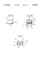
- FIGS. 11a and 11b, 12a and 12b, 13a and 13b, 14a and 14b, 15a and 15b, 16a and 16b and 17a and 17b are fragmentary views in cross-section through various differing component elements in an electrochemical assembly of the present invention
- FIGS. 18A and 18B show two intermediate steps in the manufacture of an assembly in a first example of the invention
- FIGS. 19A, 19B, and 19C show three intermediate steps in the manufacture of an assembly in a second example of the invention.
- FIG. 20 shows an intermediate step in the manufacture of an assembly in a third example of the invention.
- FIGS. 21A and 21B show two intermediate steps in the manufacture of an assembly in a fourth example of the invention.
- FIG. 22 shows an intermediate step in the manufacture of an assembly in a fifth example of the invention.
- FIGS. 23 and 24 are diagrams showing two main steps in a variant implementation of the invention.
- FIG. 25 is a diagrammatic section view through an assembly obtained at the outlet from a die for extruding electrolyte on an electrode in the context of the variant shown in FIGS. 23 and 24.
- the method of the present invention consists essentially in:
- winding a complex based on the above-specified extruded element comprising the electrolyte layer and two electrodes such as a cathode and an anode disposed respectively on opposite sides of the electrolyte, in the form of a structure having respective electrical contacts on each of different edge faces for connection with the two electrodes; and
- the extrusion step may consist in bi-extrusion of an electrode film on a film of electrolyte, or of tri-extrusion of two electrode films on an electrolyte film. It is preferably constituted by co-extrusion of at least one electrode film on the electrolyte film.
- the electrolyte film of ionic conductor polymer preferably comprises a layer of polymer material associated with a lithium salt.
- the lithium salt may be associated with the polymer material by mixing or by grafting. It is preferably mixed with a wax acting as a sliding agent, a flame retarding agent, a charge dispersion agent, and/or an agent that facilitates extrusion.
- the wax must be electrochemically inert relative to the other components of the assembly.
- the electrolyte film preferably comprises a few percent by weight of wax.
- the wax may be selected from the group of polyolefins, such as an amorphous propylene-ethylene terpolymer or a polyethylene having very low viscosity, or indeed an amide.
- Such wax is considered as being highly preferred. However it would be possible to envisage making embodiments having no wax.
- FIGS. 1 and 2 show two configurations obtained by bi-extrusion of an electrolyte film and an adjacent electrode film constituting an anode or a cathode.
- FIGS. 3 to 8 show six configurations obtained by tri-extrusion of the electrolyte film between an anode film and a cathode film.
- the sheet obtained at the end of the extrusion process is of constant thickness across its entire width.
- the two main faces of the sheet are given references 1 and 2. Its side edges are referenced 3 and 4.
- the step of co-extruding the electrolyte film and at least one electrode film is implemented through a die shaped in such a manner that the electrode is accessible on at least one main face of the extruded element and also on an edge of said element.
- the electrolyte 10 has an L-shaped profile. More particularly, the electrolyte 10 occupies one of the main faces 1 of the sheet in full and also occupies one of the two edges 3 thereof in full.
- the co-extruded electrode 50 may be an anode or a cathode. It is accessible over a fraction of the second main face 2, and over a fraction of the second edge 4 of the sheet.
- the electrolyte 10 has a U-shaped profile. More particularly, the electrolyte 10 covers one of the main faces 1 of the sheet in full and also covers both of its edges 3 and 4 in full.
- the co-extruded electrode 50 may be an anode or a cathode. It is accessible over a fraction of the second main face 2.
- the electrolyte 10 comprises an internal core 11 which extends over the entire width of the extruded sheet and which possesses extensions 12 and 13 at its respective ends that cover each of the respective edges 3 and 4 in part, with each extension 12 or 13 extending to a respective one of the main faces 1 or 2.
- the anode and cathode layers 50 and 60 are disposed on respective opposite sides of the internal core 11 and are respectively accessible over a fraction of each of the first and second main faces 1 and 2, and also of a fraction of the respective edges 3 and 4.
- the electrolyte has an H-shaped profile. More precisely, the electrolyte 10 comprises an internal core 11 which extends over the entire width of the extruded sheet and which possesses extensions 12, 13, 14, and 15 at its respective ends that occupy the respective edges 3 and 4 in full, each extending to one of the main faces 2 and 1.
- the anode and cathode layers 50 and 60 are disposed on respective opposite sides of the internal core 11 and they are accessible via respective fractions of the first and second main faces 1 and 2.
- the electrolyte 10 has a generally U-shaped profile. More precisely, the electrolyte 10 comprises a core 16 which extends perpendicularly to the two main faces 1 and 2, plus two mutually parallel branches 17 and 18 that are also parallel to the main faces 1 and 2. The core 16 is thus parallel to the edge 4. It is close thereto, but set back therefrom. Similarly, the two branches 17 and 18 are set back from the main faces 1 and 2 respectively. The free ends of the branches 17 and 18 distant from the core 16 are accessible at the second edge 3. In addition, the free ends of the branches 17 and 18 are provided with outwardly-directed extensions 19 and 20 that are accessible both from the edge 3 and from respective ones of the main faces 1 and 2.
- One of the two electrodes 50 is placed inside the volume defined by the two branches 17 and 18. Consequently, it is accessible from the edge 3.
- the other electrode 60 is placed on the outsides of the branches 17 and 18 and of the core 16. It is accessible simultaneously from both main faces 1 and 2, and from the edge 4.
- the electrolyte 10 has a U-shaped profile similar to that of FIG. 5.
- the only difference between FIGS. 6 and 5 lies in the fact that in FIG. 6, the core 16 opens out to the edge 4, and consequently the second electrolyte 60 is made up of two separate elements that are accessible from respective ones of the main faces 1 and 2.
- the electrolyte 10 has a U-shaped profile similar to FIGS. 5 and 6.
- the only difference between FIGS. 7 and 6 lies in the fact that in FIG. 7 the extensions 19 and 20 provided on the branches 17 and 18 of the electrolyte do not open out to the edge 3. These extensions 19 and 20 open out solely to the main faces 1 and 2. Consequently, the first electrode 50 provided between the branches 17 and 18 is accessible over the entire edge 3 and also over adjacent portions of the main faces 1 and 2.
- the second electrode 60 continues to be formed by two separate elements that are accessible from the main faces 1 and 2 respectively.
- the electrolyte 10 has a U-shaped profile comparable to FIGS. 5, 6, and 7.
- the only difference between FIGS. 8 and 5 lies in the fact that in FIG. 8, the extensions 19 and 20 provided on the branches 17 and 18 of the electrolyte do not open out to the edge 3. These extensions 19 and 20 open out solely to the main faces 1 and 2. Consequently, the first electrode 50 provided between the branches 17 and 18 is accessible from the entire edge 3 and also from an adjacent fraction of each of the main faces 1 and 2.
- the other electrode 60 is placed outside the branches 17 and 18, and also outside the core 16. It is accessible simultaneously from both main faces 1 and 2, and also from the edge 4.
- extruded elements shown in FIGS. 1 to 4 are preferably used in association with electrically insulating separators, e.g. based on bare plastics film or on metallized film whose metallization is on its electrode side, whereas the extruded elements shown in FIGS. 5 to 8 do not require the use of such electrically insulating separators. Nevertheless, the extruded elements shown in FIGS. 5 to 8 could be separated by conductive films.
- FIG. 9 is a diagram showing the structure of electrochemical assemblies of the kind that the invention sets out to provide.
- the cathode 80 is itself in contact with a sheet of metal 90 or with the metallization on a metallized film.
- the anode 70 may make contact in similar manner with a sheet of metal or with a metallized film. However, because of the good conductivity properties of the anode 70, it may merely be placed in contact with a film 92 that is not conductive.
- the total thickness of the multilayer structure 92, 70, 10, 80, 90 preferably lies in the range 100 ⁇ m to 500 ⁇ m.
- the calendaring is preferably performed cold. This disposition makes it easy to wind the lithium anode 70.
- the assembly step consists in spiral winding a complex based on the extruded element and having the electrolyte layer together with two electrodes such as a cathode and an anode, and preferably also together with sheets of metal or sheets of metallized plastics material.
- FIGS. 11a and 11b are obtained by assembling together two extruded complexes having the profile of FIG. 1.
- the electrolytes 10 of the two complexes are placed back-to-back such that the anode 70 and the cathode 80 are accessible from opposite edges of the winding.
- Respective metallized films 92 and 90 are deposited on the outsides of the anode 70 and of the cathode 80.
- FIGS. 12a and 12b are obtained by assembling together two extruded complexes corresponding to the profile of FIG. 2.
- the electrolytes 10 of the two complexes are back-to-back so that the anode 70 and the cathode 80 are placed on opposite faces of the winding.
- Respective metallized films 92 and 90 are deposited on the outsides of the anode 70 and of the cathode 80.
- the metallized films 92 and 90 cover the anode 70 and the cathode 80 in full, and they also cover respective marginal zones of the electrolytes adjacent to the opposite edges.
- the films are extended over the other marginal zones of the electrolyte 10 in the form of electrically insulating strips of film 93 and 91.
- the electrically insulating marginal strip 93 is adjacent to one of the edges of the winding, then the other electrically insulating marginal strip 91 is adjacent to the other edge.
- FIGS. 13a and 13b are obtained by means of an extruded complex having the profile of FIG. 3.
- Respective metallized films 92 and 90 are deposited on the outsides of the anode 70 and of the cathode 80.
- the metallized films 92 and 90 respectively cover the anode 70 and the cathode 80 in full.
- the films are extended over the electrolyte 10 in the form of respective electrically insulating marginal strips of film 93 and 91.
- FIGS. 14a and 14b are obtained by assembling together two extruded complexes corresponding to the profile of FIG. 3.
- One of the electrodes 50 of a first complex is placed in contact with the electrode 50 of the same kind belonging to the second complex such that the anode 70 and the cathode 80 are accessible from opposite edges of the winding.
- a metallized film 92, 90 is deposited on the outside of the second electrode.
- the metallized film 92, 90 covers said second electrode in full. It is extended over the electrolyte 10 by respective electrically insulating marginal strips of film 93 and 91.
- FIGS. 15a and 15b are obtained by means of an extruded complex corresponding to the profile of FIG. 4.
- Respective metallized films 92 and 90 are deposited on the outsides of the anode 70 and of the cathode 80.
- the metallized films 92 and 90 respectively cover the anode 70 and the cathode 80 in full.
- the films are extended over the electrolyte 10 by respective electrically insulating marginal strips of film 93 and 91.
- FIGS. 16a and 16b The assembly shown in FIGS. 16a and 16b are obtained by means of an extruded complex corresponding to the profile of FIG. 6.
- Two metallized films 92 and 90 are deposited on the outside electrode.
- the metallized films 92 and 90 cover the outside electrode in full. Over the electrolyte 10, they are extended by respective electrically insulating marginal strips of film 93 and 91.
- FIGS. 17a and 17b The assembly shown in FIGS. 17a and 17b are obtained by means of an extruded complex corresponding to the profile of FIG. 5.
- Two metallized films 92 and 90 are deposited on the outside electrode.
- the metallized films 92 and 90 cover the outside electrode in full. Over the electrolyte 10, they are extended by respective electrically insulating marginal strips of film 93 and 91.
- cylindrical unit cells obtained by spiral winding the assembly can be compressed and considered as disks.
- Electrical connections are made via the edges of the windings by depositing a molten phase of metal or metal alloy having a low melting point and good electrical conductivity. This may be done by means of an electric spray gun (implementing a Schoop-like process).
- the metallized films 90 are preferably polypropylene films having a thickness of 15 ⁇ m to 25 ⁇ m and they are coated with nickel having a thickness of 20 nm to 100 nm with deposition being performed by an electron gun or by evaporation due to the Joule effect.
- the non-metallized films 92 are preferably polypropylene films having a thickness of 15 ⁇ m to 25 ⁇ m.
- the lithium electrode may be made by cold calendaring, by spreading on lithium in the liquid phase, or by vacuum deposition.
- This first example consists initially in co-extruding the electrolyte 10 and the cathode 80 using the profile of FIG. 1 and the following compositions:
- the assembly 10/80 obtained in this way had its cathode side 80 deposited on a sheet 90 of polypropylene metallized with nickel 100 and having a 5 mm wide non-metallized margin 102 adjacent to the electrolyte, as can be seen in FIG. 18A.
- a sheet of rolled lithium was prepared to form the anode 70.
- a 300 ⁇ m thick lithium tape is preferably reduced to a thickness of 100 ⁇ m by cold rolling between two polypropylene spacers 104 that are 100 ⁇ m thick and 5 mm wide.
- the resulting complex was calendared, with one of the spacers 104 being retained and with a polypropylene film 92 being placed on the lithium anode 70, as can be seen in FIG. 18B.
- the spacer 104 was positioned in such a manner that the anode 70 and the cathode 80 were accessible from different edges.
- the complex 92, 70, 10, 80, 100, 90 was spiral wound and two nickel connections were deposited on each end or edge of the winding by deposition using an electric spray gun.
- the second example consists initially in co-extruding the electrolyte 10 and the cathode 80 with the profile of FIG. 1 and having the following compositions:
- This first complex comprising the cathode 80 and the electrolyte 10 was deposited on a stainless metal sheet 90, e.g. made of nickel, having a thickness of 5 ⁇ m, as shown in FIG. 19A.
- a two-layer assembly comprising a lithium anode 70 and the electrolyte 10 having the profile of FIG. 1 was also made. That assembly is preferably made by cold extrusion. The anode side 70 of this assembly 10, 70 was then deposited on a film 92 of metal-coated polypropylene having a thickness of 12 ⁇ m. After the electrolytes 10 of the two complexes had been juxtaposed, as shown in FIG. 19C, so that the lithium anode 70 and the cathode 80 were available via opposite edges, the complexes were calendared together.
- the third example consists initially in making a three-layer co-extrusion of cathode 80, electrolyte 10, and anode 70, having the profile of FIG. 3, and as shown in FIG. 20, the compositions were as follows:
- the cathode side 80 of the above extruded three-layer complex 70, 10, 80 was deposited on a polyethylene film 90 metallized at 100with a layer of stainless metal or metal alloy, e.g. nickel or stainless steel, leaving a margin 102 on the electrolyte side.
- the complex was then spiral wound and electrical connections were made on the edges of the winding, as in Example 1.
- the above examples relate to manufacturing an electric battery cell.
- the two electrodes on opposite sides of the electrolyte 10 are identical in kind.
- the fourth example consists initially in making a two-layer extrusion comprising an electrolyte layer 10 having the same composition as Example 1, on an electrode layer 75 having the following composition, with the profile being as shown in FIG. 1:
- the electrode side 75 of the resulting extruded two-layer complex 10, 75 was deposited on a film 90 of polypropylene metallized with nickel 100 and leaving a 5 mm wide margin 102 on the electrolyte side, as can be seen in FIG. 21A.
- the fifth example consists initially in making a three-layer extrusion comprising an electrode 75, an electrolyte 10, and an electrode 75 with the profile of FIG. 3, and having the following compositions:
- PVDF ethylene polyoxide 48% by weight
- the extruded three-layer complex 75, 10, 75 is deposited between two films 110 of polyethylene or polypropylene metal-coated with stainless steel or nickel 112, leaving a margin 114 on the electrolyte side.
- the assembly was calendared and spiral wound.
- the elements Prior to being insulated in a package or a block of resin, the elements are impregnated with an organic solvent in which a salt has been dissolved, a propylene carbonate solvent and a salt such as lithium bi (trifluoro sulfonate) imide constituting 45% by weight.
- the method of the present invention includes a first step which consists in preparing an electrode 80, a cathode or an anode, by calendaring CAST extrusion.
- a CAST extrusion process consists in receiving the extruded material at the outlet from the die on a support, preferably a heated support, that is adapted to enable the extruded material to be stretched.
- overall reference 200 designates the extruder for the electrode 80.
- the electrode film 80 is preferably protected over both its main faces by two protective sheets 210 and 212, or by a protective sheet 210 and by a current collector 212.
- the protective sheets 210 and 212 are preferably made of polyester.
- the sheet that is used as a current collector is preferably made of a metallized plastics sheet.
- the electrode 80 protected in this way by the sheets 210 and 212 is then preferably subjected to a calendaring operation in a calendaring station 220, with one or both of the cylinders of the calendaring station 220 being heated to a temperature in the range 30° C. to 50° C.
- the calendaring operation can be implemented in one or more steps. It is preferably adapted to obtain a thin film electrode 80 whose thickness lies in the range 170 ⁇ m to 40 ⁇ m.
- the second step consists, after removing the protective sheets 210 and 212 as shown diagrammatically in FIG. 24, in partially coating the electrode 80 with electrolyte 10, in an extrusion operation that takes place through a die that is represented at reference 230 in FIG. 24.
- the current collector sheet is kept on the electrode 80 as it passes through the die 230.
- FIG. 25 is a section view of the assembly obtained at the outlet from the die 230, with the electrolyte 10 being represented as being L-shaped, in a manner comparable to FIG. 1. This disposition should nevertheless not be considered as being limiting. In practice, this variant implementation as shown in FIGS. 23 and 24 can be used to form an electrolyte with any of the shapes described above and shown in the preceding figures.
- the second electrode 70 may be deposited on the assembly obtained at the outlet from the die 230 by any appropriate means.
- the second electrode 70 may be co-extruded with the electrolyte 10 in the die 230, or it may be made separately and be deposited on the complex 10, 80 as described above.
- the present invention offers the following advantages, in particular:
- the thicknesses of the various layers used and the uniformity thereof can be controlled accurately.
Landscapes
- Manufacturing & Machinery (AREA)
- Chemical & Material Sciences (AREA)
- Chemical Kinetics & Catalysis (AREA)
- Electrochemistry (AREA)
- General Chemical & Material Sciences (AREA)
- Engineering & Computer Science (AREA)
- Secondary Cells (AREA)
- Electric Double-Layer Capacitors Or The Like (AREA)
- Primary Cells (AREA)
- Battery Electrode And Active Subsutance (AREA)
- Electrolytic Production Of Non-Metals, Compounds, Apparatuses Therefor (AREA)
- Extrusion Moulding Of Plastics Or The Like (AREA)
- Laminated Bodies (AREA)
Applications Claiming Priority (2)
| Application Number | Priority Date | Filing Date | Title |
|---|---|---|---|
| FR9313635A FR2712733B1 (fr) | 1993-11-16 | 1993-11-16 | Procédé de fabrication d'un ensemble électrochimique multicouche comprenant un électrolyte entre deux électrodes et ensemble ainsi réalisé. |
| FR9313635 | 1993-11-16 |
Publications (1)
| Publication Number | Publication Date |
|---|---|
| US5593462A true US5593462A (en) | 1997-01-14 |
Family
ID=9452884
Family Applications (1)
| Application Number | Title | Priority Date | Filing Date |
|---|---|---|---|
| US08/339,017 Expired - Lifetime US5593462A (en) | 1993-11-16 | 1994-11-14 | Method of manufacturing a multilayer electrochemical assembly comprising an electrolyte between two electrodes, and an assembly made thereby |
Country Status (9)
| Country | Link |
|---|---|
| US (1) | US5593462A (de) |
| EP (1) | EP0657951B1 (de) |
| JP (1) | JP3580871B2 (de) |
| AT (1) | ATE154470T1 (de) |
| DE (1) | DE69403761T2 (de) |
| DK (1) | DK0657951T3 (de) |
| ES (1) | ES2105571T3 (de) |
| FR (1) | FR2712733B1 (de) |
| GR (1) | GR3024681T3 (de) |
Cited By (54)
| Publication number | Priority date | Publication date | Assignee | Title |
|---|---|---|---|---|
| US5998059A (en) * | 1996-12-31 | 1999-12-07 | Samsung Display Devices Co., Ltd. | Cylindrical battery employing a separator having a protruding part |
| US6168681B1 (en) | 1995-05-12 | 2001-01-02 | Donaldson & Company, Inc. | Method of making a filter device |
| US6235065B1 (en) | 1998-10-27 | 2001-05-22 | Alcatel | Room temperature lamination of Li-ion polymer electrodes |
| US6503432B1 (en) | 2000-03-02 | 2003-01-07 | E. I. Du Pont De Nemours And Company | Process for forming multilayer articles by melt extrusion |
| US20030013007A1 (en) * | 2001-07-13 | 2003-01-16 | Kaun Thomas D. | Cell structure for electrochemical devices and method of making same |
| US6524742B1 (en) * | 1999-02-19 | 2003-02-25 | Amtek Research International Llc | Electrically conductive, freestanding microporous polymer sheet |
| US6589299B2 (en) | 2001-02-13 | 2003-07-08 | 3M Innovative Properties Company | Method for making electrode |
| US6627252B1 (en) | 2000-05-12 | 2003-09-30 | Maxwell Electronic Components, Inc. | Electrochemical double layer capacitor having carbon powder electrodes |
| US6643119B2 (en) | 2001-11-02 | 2003-11-04 | Maxwell Technologies, Inc. | Electrochemical double layer capacitor having carbon powder electrodes |
| US20030205835A1 (en) * | 2002-05-03 | 2003-11-06 | 3M Innovative Properties Company | Method for making electrode |
| US20040159964A1 (en) * | 2002-12-02 | 2004-08-19 | Paul-Andre Lavoie | Co-extrusion manufacturing process of thin film electrochemical cell for lithium polymer batteries and apparatus therefor |
| US20050037262A1 (en) * | 2003-08-01 | 2005-02-17 | Alain Vallee | Cathode material for polymer batteries and method of preparing same |
| US6955694B2 (en) | 2000-05-12 | 2005-10-18 | Maxwell Technologies, Inc. | Electrochemical double layer capacitor having carbon powder electrodes |
| US20050233212A1 (en) * | 2004-04-14 | 2005-10-20 | Kaun Thomas D | Housing for electrochemical devices |
| US20050250011A1 (en) * | 2004-04-02 | 2005-11-10 | Maxwell Technologies, Inc. | Particle packaging systems and methods |
| US20050266298A1 (en) * | 2003-07-09 | 2005-12-01 | Maxwell Technologies, Inc. | Dry particle based electro-chemical device and methods of making same |
| US20060085972A1 (en) * | 2004-10-21 | 2006-04-27 | Anthony Sudano | Thin film electrochemical cell for lithium polymer batteries and manufacturing method therefor |
| US20060114643A1 (en) * | 2004-04-02 | 2006-06-01 | Maxwell Technologies, Inc. | Particles based electrodes and methods of making same |
| US20060133012A1 (en) * | 2003-07-09 | 2006-06-22 | Maxwell Technologies, Inc. | Dry particle based capacitor and methods of making same |
| US20060133013A1 (en) * | 2003-07-09 | 2006-06-22 | Maxwell Technologies, Inc. | Dry particle based adhesive and dry film and methods of making same |
| US20060137158A1 (en) * | 2004-04-02 | 2006-06-29 | Maxwell Technologies, Inc. | Dry-particle packaging systems and methods of making same |
| US20060146479A1 (en) * | 2003-07-09 | 2006-07-06 | Maxwell Technologies, Inc. | Recyclable dry particle based adhesive electrode and methods of making same |
| US20060147712A1 (en) * | 2003-07-09 | 2006-07-06 | Maxwell Technologies, Inc. | Dry particle based adhesive electrode and methods of making same |
| US20060246343A1 (en) * | 2004-04-02 | 2006-11-02 | Maxwell Technologies, Inc. | Dry particle packaging systems and methods of making same |
| US20070026317A1 (en) * | 2004-02-19 | 2007-02-01 | Porter Mitchell | Composite electrode and method for fabricating same |
| US7227737B2 (en) | 2004-04-02 | 2007-06-05 | Maxwell Technologies, Inc. | Electrode design |
| DE10118639B4 (de) * | 2001-04-12 | 2007-06-14 | Dilo Trading Ag | Verfahren zur kontinuierlichen Herstellung von Trilaminaten für Polymer-Lithium Batterien |
| US20070160901A1 (en) * | 2001-07-13 | 2007-07-12 | Inventex Corporation | Cell structure for electrochemical devices and method of making same |
| US7245478B2 (en) | 2004-08-16 | 2007-07-17 | Maxwell Technologies, Inc. | Enhanced breakdown voltage electrode |
| US20070198230A1 (en) * | 2006-02-20 | 2007-08-23 | Ford Global Technologies, Llc | Parametric modeling method and system for conceptual vehicle design |
| US7295423B1 (en) | 2003-07-09 | 2007-11-13 | Maxwell Technologies, Inc. | Dry particle based adhesive electrode and methods of making same |
| US20080022517A1 (en) * | 2001-05-22 | 2008-01-31 | Sri International | Rolled electroactive polymers |
| US7382046B2 (en) | 2003-10-07 | 2008-06-03 | Fujitsu Limited | Semiconductor device protection cover, and semiconductor device unit including the cover |
| US7492574B2 (en) | 2005-03-14 | 2009-02-17 | Maxwell Technologies, Inc. | Coupling of cell to housing |
| US7495349B2 (en) | 2003-10-20 | 2009-02-24 | Maxwell Technologies, Inc. | Self aligning electrode |
| US20100014215A1 (en) * | 2004-04-02 | 2010-01-21 | Maxwell Technologies, Inc. | Recyclable dry particle based electrode and methods of making same |
| US7791860B2 (en) | 2003-07-09 | 2010-09-07 | Maxwell Technologies, Inc. | Particle based electrodes and methods of making same |
| US7811337B2 (en) | 2007-02-28 | 2010-10-12 | Maxwell Technologies, Inc. | Ultracapacitor electrode with controlled sulfur content |
| US20100273061A1 (en) * | 2006-09-29 | 2010-10-28 | Maxwell Technologies, Inc. | Low-inductive impedance, thermally decoupled, radii-modulated electrode core |
| US7859826B2 (en) | 2005-03-14 | 2010-12-28 | Maxwell Technologies, Inc. | Thermal interconnects for coupling energy storage devices |
| US7882622B2 (en) | 2005-12-22 | 2011-02-08 | Electrochem Solutions, Inc. | Apparatus and method for fabricating cathode collectors for lithium/oxyhalide electrochemical cells |
| US7883553B2 (en) | 2004-02-19 | 2011-02-08 | Maxwell Technologies, Inc. | Method of manufacturing an electrode product |
| US7920371B2 (en) | 2003-09-12 | 2011-04-05 | Maxwell Technologies, Inc. | Electrical energy storage devices with separator between electrodes and methods for fabricating the devices |
| US8815443B2 (en) | 2003-07-09 | 2014-08-26 | Maxwell Technologies, Inc. | Dry-particle based adhesive and dry film and methods of making same |
| US9195058B2 (en) | 2011-03-22 | 2015-11-24 | Parker-Hannifin Corporation | Electroactive polymer actuator lenticular system |
| US9231186B2 (en) | 2009-04-11 | 2016-01-05 | Parker-Hannifin Corporation | Electro-switchable polymer film assembly and use thereof |
| US9425383B2 (en) | 2007-06-29 | 2016-08-23 | Parker-Hannifin Corporation | Method of manufacturing electroactive polymer transducers for sensory feedback applications |
| US9553254B2 (en) | 2011-03-01 | 2017-01-24 | Parker-Hannifin Corporation | Automated manufacturing processes for producing deformable polymer devices and films |
| US9590193B2 (en) | 2012-10-24 | 2017-03-07 | Parker-Hannifin Corporation | Polymer diode |
| US9590233B2 (en) | 2013-04-05 | 2017-03-07 | Duracell U.S. Operations, Inc. | Method of making a cathode |
| US9761790B2 (en) | 2012-06-18 | 2017-09-12 | Parker-Hannifin Corporation | Stretch frame for stretching process |
| US9876160B2 (en) | 2012-03-21 | 2018-01-23 | Parker-Hannifin Corporation | Roll-to-roll manufacturing processes for producing self-healing electroactive polymer devices |
| US10037850B2 (en) | 2014-12-18 | 2018-07-31 | 3M Innovative Properties Company | Multilayer film capacitor |
| EP3404740A1 (de) * | 2017-05-18 | 2018-11-21 | Panasonic Intellectual Property Management Co., Ltd. | Batterie |
Families Citing this family (7)
| Publication number | Priority date | Publication date | Assignee | Title |
|---|---|---|---|---|
| FR2755795A1 (fr) * | 1996-11-12 | 1998-05-15 | Electricite De France | Collecteur de courant pour electrode positive et eventuellement electrode negative pour un ensemble electrochimique multicouche et pour bobinage ainsi obtenu |
| JP4714952B2 (ja) * | 1998-10-30 | 2011-07-06 | ソニー株式会社 | リチウムイオンポリマ二次電池及びその製造装置並びに製造方法 |
| JP4873281B2 (ja) * | 2001-04-20 | 2012-02-08 | 住友電気工業株式会社 | リチウム電池負極の製造方法 |
| FR2915626B1 (fr) | 2007-04-24 | 2010-10-29 | Batscap Sa | Module pour ensemble de stockage d'energie electrique |
| FR2916306B1 (fr) | 2007-05-15 | 2009-07-17 | Batscap Sa | Module pour ensembles de stockage d'energie electrique permettant la detection du vieillissement desdits ensembles. |
| KR20170032001A (ko) * | 2015-09-14 | 2017-03-22 | 주식회사 엘지화학 | 리튬금속 전극 및 이를 포함하는 리튬 이차전지 |
| DE112024002895A5 (de) | 2023-07-10 | 2026-04-23 | Troester Gmbh & Co. Kg | Verfahren zur Herstellung eines lösungsmittelfreien Elektrodencompounds sowie ein Verfahren zum Ausbringen einer Vorlage mittels einer Austragsvorrichtung |
Citations (11)
| Publication number | Priority date | Publication date | Assignee | Title |
|---|---|---|---|---|
| US2280789A (en) * | 1937-08-09 | 1942-04-28 | Joseph B Brennan | Electrolytic device |
| US3429747A (en) * | 1965-12-11 | 1969-02-25 | Varta Ag | Electric cell |
| US3434203A (en) * | 1965-11-27 | 1969-03-25 | Ferranti Ltd | Manufacture of thermo-electric generators |
| US4281492A (en) * | 1978-06-24 | 1981-08-04 | Schock & Co. | Sectional construction strip, e.g. for the production of window frames |
| EP0145498A2 (de) * | 1983-12-15 | 1985-06-19 | Scimat Limited | Materialien für elektrische Vorrichtungen |
| US4605527A (en) * | 1983-09-24 | 1986-08-12 | Nippon Valqua Kogyo Kabushiki Kaisha | Process for producing clutch facings |
| US4783384A (en) * | 1987-07-28 | 1988-11-08 | U.S. Philips Corporation | Electrochemical cell |
| US5132070A (en) * | 1990-08-17 | 1992-07-21 | Paul Marlene L | Process for the manufacture of composite parts |
| US5219673A (en) * | 1991-08-23 | 1993-06-15 | Kaun Thomas D | Cell structure for electrochemical devices and method of making same |
| US5442197A (en) * | 1991-12-13 | 1995-08-15 | Alcatel Alsthom Compagnie Generale D'electricite | Super-capacitor comprising positive and negative electrodes made of a p-doped electron conductive polymer and an electrolyte containing an organic redox compound |
| US5445906A (en) * | 1994-08-03 | 1995-08-29 | Martin Marietta Energy Systems, Inc. | Method and system for constructing a rechargeable battery and battery structures formed with the method |
-
1993
- 1993-11-16 FR FR9313635A patent/FR2712733B1/fr not_active Expired - Fee Related
-
1994
- 1994-11-14 AT AT94402564T patent/ATE154470T1/de not_active IP Right Cessation
- 1994-11-14 DK DK94402564.2T patent/DK0657951T3/da active
- 1994-11-14 DE DE69403761T patent/DE69403761T2/de not_active Expired - Lifetime
- 1994-11-14 ES ES94402564T patent/ES2105571T3/es not_active Expired - Lifetime
- 1994-11-14 EP EP94402564A patent/EP0657951B1/de not_active Expired - Lifetime
- 1994-11-14 US US08/339,017 patent/US5593462A/en not_active Expired - Lifetime
- 1994-11-15 JP JP28059594A patent/JP3580871B2/ja not_active Expired - Lifetime
-
1997
- 1997-09-10 GR GR970402327T patent/GR3024681T3/el unknown
Patent Citations (11)
| Publication number | Priority date | Publication date | Assignee | Title |
|---|---|---|---|---|
| US2280789A (en) * | 1937-08-09 | 1942-04-28 | Joseph B Brennan | Electrolytic device |
| US3434203A (en) * | 1965-11-27 | 1969-03-25 | Ferranti Ltd | Manufacture of thermo-electric generators |
| US3429747A (en) * | 1965-12-11 | 1969-02-25 | Varta Ag | Electric cell |
| US4281492A (en) * | 1978-06-24 | 1981-08-04 | Schock & Co. | Sectional construction strip, e.g. for the production of window frames |
| US4605527A (en) * | 1983-09-24 | 1986-08-12 | Nippon Valqua Kogyo Kabushiki Kaisha | Process for producing clutch facings |
| EP0145498A2 (de) * | 1983-12-15 | 1985-06-19 | Scimat Limited | Materialien für elektrische Vorrichtungen |
| US4783384A (en) * | 1987-07-28 | 1988-11-08 | U.S. Philips Corporation | Electrochemical cell |
| US5132070A (en) * | 1990-08-17 | 1992-07-21 | Paul Marlene L | Process for the manufacture of composite parts |
| US5219673A (en) * | 1991-08-23 | 1993-06-15 | Kaun Thomas D | Cell structure for electrochemical devices and method of making same |
| US5442197A (en) * | 1991-12-13 | 1995-08-15 | Alcatel Alsthom Compagnie Generale D'electricite | Super-capacitor comprising positive and negative electrodes made of a p-doped electron conductive polymer and an electrolyte containing an organic redox compound |
| US5445906A (en) * | 1994-08-03 | 1995-08-29 | Martin Marietta Energy Systems, Inc. | Method and system for constructing a rechargeable battery and battery structures formed with the method |
Cited By (101)
| Publication number | Priority date | Publication date | Assignee | Title |
|---|---|---|---|---|
| US6168681B1 (en) | 1995-05-12 | 2001-01-02 | Donaldson & Company, Inc. | Method of making a filter device |
| US5998059A (en) * | 1996-12-31 | 1999-12-07 | Samsung Display Devices Co., Ltd. | Cylindrical battery employing a separator having a protruding part |
| US6235065B1 (en) | 1998-10-27 | 2001-05-22 | Alcatel | Room temperature lamination of Li-ion polymer electrodes |
| US20040010909A1 (en) * | 1999-02-19 | 2004-01-22 | James Emanuel | Method of forming an electrically conductive, freestanding microporous polymer sheet |
| US6524742B1 (en) * | 1999-02-19 | 2003-02-25 | Amtek Research International Llc | Electrically conductive, freestanding microporous polymer sheet |
| US6503432B1 (en) | 2000-03-02 | 2003-01-07 | E. I. Du Pont De Nemours And Company | Process for forming multilayer articles by melt extrusion |
| US20030054245A1 (en) * | 2000-03-02 | 2003-03-20 | Barton Kelly D. | Process for forming multilayer articles by melt extrusion |
| US6986967B2 (en) * | 2000-03-02 | 2006-01-17 | E. I. Du Pont De Nemours And Company, Inc. | Multilayer structure including an active electrochemical material and ionic polymer in a electrochemical cell |
| US6627252B1 (en) | 2000-05-12 | 2003-09-30 | Maxwell Electronic Components, Inc. | Electrochemical double layer capacitor having carbon powder electrodes |
| US6955694B2 (en) | 2000-05-12 | 2005-10-18 | Maxwell Technologies, Inc. | Electrochemical double layer capacitor having carbon powder electrodes |
| US6804108B2 (en) | 2000-05-12 | 2004-10-12 | Maxwell Electronics, Inc. | Electrochemical double layer capacitor having carbon powder electrodes |
| US6589299B2 (en) | 2001-02-13 | 2003-07-08 | 3M Innovative Properties Company | Method for making electrode |
| DE10118639B4 (de) * | 2001-04-12 | 2007-06-14 | Dilo Trading Ag | Verfahren zur kontinuierlichen Herstellung von Trilaminaten für Polymer-Lithium Batterien |
| US8042264B2 (en) | 2001-05-22 | 2011-10-25 | Sri International | Method of fabricating an electroactive polymer transducer |
| US20080022517A1 (en) * | 2001-05-22 | 2008-01-31 | Sri International | Rolled electroactive polymers |
| US7761981B2 (en) * | 2001-05-22 | 2010-07-27 | Sri International | Methods for fabricating an electroactive polymer device |
| US20100263181A1 (en) * | 2001-05-22 | 2010-10-21 | Sri International | Rolled electroactive polymers |
| US20110025170A1 (en) * | 2001-05-22 | 2011-02-03 | Sri International | Electroactive polymer device |
| US8093783B2 (en) | 2001-05-22 | 2012-01-10 | Sri International | Electroactive polymer device |
| US8021775B2 (en) | 2001-07-13 | 2011-09-20 | Inventek Corporation | Cell structure for electrochemical devices and method of making same |
| US7195840B2 (en) | 2001-07-13 | 2007-03-27 | Kaun Thomas D | Cell structure for electrochemical devices and method of making same |
| US20030013007A1 (en) * | 2001-07-13 | 2003-01-16 | Kaun Thomas D. | Cell structure for electrochemical devices and method of making same |
| US8263248B2 (en) | 2001-07-13 | 2012-09-11 | Inventek Corporation | Cell structure for electrochemical devices and method of making same |
| US20070160901A1 (en) * | 2001-07-13 | 2007-07-12 | Inventex Corporation | Cell structure for electrochemical devices and method of making same |
| US6643119B2 (en) | 2001-11-02 | 2003-11-04 | Maxwell Technologies, Inc. | Electrochemical double layer capacitor having carbon powder electrodes |
| US6946007B2 (en) | 2001-11-02 | 2005-09-20 | Sony Corporation | Electrochemical double layer capacitor having carbon powder electrodes |
| US6939383B2 (en) | 2002-05-03 | 2005-09-06 | 3M Innovative Properties Company | Method for making electrode |
| US20030205835A1 (en) * | 2002-05-03 | 2003-11-06 | 3M Innovative Properties Company | Method for making electrode |
| US20040159964A1 (en) * | 2002-12-02 | 2004-08-19 | Paul-Andre Lavoie | Co-extrusion manufacturing process of thin film electrochemical cell for lithium polymer batteries and apparatus therefor |
| US7700019B2 (en) | 2002-12-02 | 2010-04-20 | Bathium Canada Inc. | Co-extrusion manufacturing process of thin film electrochemical cell for lithium polymer batteries and apparatus therefor |
| US20060133013A1 (en) * | 2003-07-09 | 2006-06-22 | Maxwell Technologies, Inc. | Dry particle based adhesive and dry film and methods of making same |
| US20080102371A1 (en) * | 2003-07-09 | 2008-05-01 | Maxwell Technologies, Inc. | Dry particle based adhesive electrode and methods of making same |
| US11430613B2 (en) | 2003-07-09 | 2022-08-30 | Tesla, Inc. | Recyclable dry-particle based adhesive electrode and methods of making same |
| US10547057B2 (en) | 2003-07-09 | 2020-01-28 | Maxwell Technologies, Inc. | Dry-particle based adhesive and dry film and methods of making same |
| US20060147712A1 (en) * | 2003-07-09 | 2006-07-06 | Maxwell Technologies, Inc. | Dry particle based adhesive electrode and methods of making same |
| US20060146479A1 (en) * | 2003-07-09 | 2006-07-06 | Maxwell Technologies, Inc. | Recyclable dry particle based adhesive electrode and methods of making same |
| US9525168B2 (en) | 2003-07-09 | 2016-12-20 | Maxwell Technologies, Inc. | Dry-particle based adhesive and dry film and methods of making same |
| US8815443B2 (en) | 2003-07-09 | 2014-08-26 | Maxwell Technologies, Inc. | Dry-particle based adhesive and dry film and methods of making same |
| US7508651B2 (en) | 2003-07-09 | 2009-03-24 | Maxwell Technologies, Inc. | Dry particle based adhesive and dry film and methods of making same |
| US7295423B1 (en) | 2003-07-09 | 2007-11-13 | Maxwell Technologies, Inc. | Dry particle based adhesive electrode and methods of making same |
| US7791860B2 (en) | 2003-07-09 | 2010-09-07 | Maxwell Technologies, Inc. | Particle based electrodes and methods of making same |
| US7791861B2 (en) | 2003-07-09 | 2010-09-07 | Maxwell Technologies, Inc. | Dry particle based energy storage device product |
| US8213156B2 (en) | 2003-07-09 | 2012-07-03 | Maxwell Technologies, Inc. | Particle based electrodes and methods of making same |
| US7342770B2 (en) | 2003-07-09 | 2008-03-11 | Maxwell Technologies, Inc. | Recyclable dry particle based adhesive electrode and methods of making same |
| US7352558B2 (en) | 2003-07-09 | 2008-04-01 | Maxwell Technologies, Inc. | Dry particle based capacitor and methods of making same |
| US20080092808A1 (en) * | 2003-07-09 | 2008-04-24 | Maxwell Technologies, Inc. | Dry Particle Based Adhesive Electrode and Methods of Making Same |
| US20060133012A1 (en) * | 2003-07-09 | 2006-06-22 | Maxwell Technologies, Inc. | Dry particle based capacitor and methods of making same |
| US8072734B2 (en) | 2003-07-09 | 2011-12-06 | Maxwell Technologies, Inc. | Dry particle based energy storage device product |
| US20050266298A1 (en) * | 2003-07-09 | 2005-12-01 | Maxwell Technologies, Inc. | Dry particle based electro-chemical device and methods of making same |
| US20080206446A1 (en) * | 2003-07-09 | 2008-08-28 | Maxwell Technologies, Inc. | Recyclable dry-particle based adhesive electrode and methods of making same |
| US8241541B2 (en) | 2003-08-01 | 2012-08-14 | Bathium Canada Inc. | Cathode material for polymer batteries and method of preparing same |
| US20070273062A1 (en) * | 2003-08-01 | 2007-11-29 | Bathium Canada Inc. | Cathode Material for Polymer Batteries and Method of Preparing Same |
| US20050037262A1 (en) * | 2003-08-01 | 2005-02-17 | Alain Vallee | Cathode material for polymer batteries and method of preparing same |
| US7920371B2 (en) | 2003-09-12 | 2011-04-05 | Maxwell Technologies, Inc. | Electrical energy storage devices with separator between electrodes and methods for fabricating the devices |
| US8268670B2 (en) | 2003-10-07 | 2012-09-18 | Fujitsu Semiconductor Limited | Method of semiconductor device protection |
| US20110049699A1 (en) * | 2003-10-07 | 2011-03-03 | Fujitsu Semiconductor Limited | Method of semiconductor device protection, package of semiconductor device |
| US7382046B2 (en) | 2003-10-07 | 2008-06-03 | Fujitsu Limited | Semiconductor device protection cover, and semiconductor device unit including the cover |
| US8164181B2 (en) | 2003-10-07 | 2012-04-24 | Fujitsu Semiconductor Limited | Semiconductor device packaging structure |
| US7495349B2 (en) | 2003-10-20 | 2009-02-24 | Maxwell Technologies, Inc. | Self aligning electrode |
| US7851238B2 (en) | 2003-10-20 | 2010-12-14 | Maxwell Technologies, Inc. | Method for fabricating self-aligning electrode |
| US20090223630A1 (en) * | 2003-10-20 | 2009-09-10 | Maxwell Technologies, Inc. | Method for Self Aligning Electrode |
| US7935155B2 (en) | 2004-02-19 | 2011-05-03 | Maxwell Technologies, Inc. | Method of manufacturing an electrode or capacitor product |
| US7722686B2 (en) | 2004-02-19 | 2010-05-25 | Maxwell Technologies, Inc. | Composite electrode and method for fabricating same |
| US7883553B2 (en) | 2004-02-19 | 2011-02-08 | Maxwell Technologies, Inc. | Method of manufacturing an electrode product |
| US20070026317A1 (en) * | 2004-02-19 | 2007-02-01 | Porter Mitchell | Composite electrode and method for fabricating same |
| US20080016664A1 (en) * | 2004-04-02 | 2008-01-24 | Maxwell Technologies, Inc. | Electrode design |
| US7227737B2 (en) | 2004-04-02 | 2007-06-05 | Maxwell Technologies, Inc. | Electrode design |
| US20060114643A1 (en) * | 2004-04-02 | 2006-06-01 | Maxwell Technologies, Inc. | Particles based electrodes and methods of making same |
| US20060246343A1 (en) * | 2004-04-02 | 2006-11-02 | Maxwell Technologies, Inc. | Dry particle packaging systems and methods of making same |
| US7492571B2 (en) | 2004-04-02 | 2009-02-17 | Linda Zhong | Particles based electrodes and methods of making same |
| US20070190424A1 (en) * | 2004-04-02 | 2007-08-16 | Maxwell Technologies, Inc. | Dry-particle packaging systems and methods of making same |
| US20060137158A1 (en) * | 2004-04-02 | 2006-06-29 | Maxwell Technologies, Inc. | Dry-particle packaging systems and methods of making same |
| US20050250011A1 (en) * | 2004-04-02 | 2005-11-10 | Maxwell Technologies, Inc. | Particle packaging systems and methods |
| US20100014215A1 (en) * | 2004-04-02 | 2010-01-21 | Maxwell Technologies, Inc. | Recyclable dry particle based electrode and methods of making same |
| US20050233212A1 (en) * | 2004-04-14 | 2005-10-20 | Kaun Thomas D | Housing for electrochemical devices |
| US8734983B2 (en) | 2004-04-14 | 2014-05-27 | Inventek Corporation | Housing for electrochemical devices |
| US7245478B2 (en) | 2004-08-16 | 2007-07-17 | Maxwell Technologies, Inc. | Enhanced breakdown voltage electrode |
| US20060085972A1 (en) * | 2004-10-21 | 2006-04-27 | Anthony Sudano | Thin film electrochemical cell for lithium polymer batteries and manufacturing method therefor |
| EP1825555A4 (de) * | 2004-10-21 | 2008-08-13 | Avestor Ltd Partnership | Elektrochemische dünnfilm-zelle für lithium-polymerbatterien und herstellungsverfahren dafür |
| EP2328222A1 (de) * | 2004-10-21 | 2011-06-01 | Bathium Canada Inc. | Elektrochemische dünnfilm-zelle für lithium-polymerbatterien und herstellungsverfahren dafür |
| WO2006042416A1 (en) | 2004-10-21 | 2006-04-27 | Avestor Limited Patnership | Thin film electrochemical cell for lithium polymer batteries and manufacturing method therefor |
| US7531012B2 (en) | 2004-10-21 | 2009-05-12 | Bathium Canada Inc. | Thin film electrochemical cell for lithium polymer batteries and manufacturing method therefor |
| US7859826B2 (en) | 2005-03-14 | 2010-12-28 | Maxwell Technologies, Inc. | Thermal interconnects for coupling energy storage devices |
| US7492574B2 (en) | 2005-03-14 | 2009-02-17 | Maxwell Technologies, Inc. | Coupling of cell to housing |
| US7882622B2 (en) | 2005-12-22 | 2011-02-08 | Electrochem Solutions, Inc. | Apparatus and method for fabricating cathode collectors for lithium/oxyhalide electrochemical cells |
| US20070198230A1 (en) * | 2006-02-20 | 2007-08-23 | Ford Global Technologies, Llc | Parametric modeling method and system for conceptual vehicle design |
| US20100273061A1 (en) * | 2006-09-29 | 2010-10-28 | Maxwell Technologies, Inc. | Low-inductive impedance, thermally decoupled, radii-modulated electrode core |
| US8518573B2 (en) | 2006-09-29 | 2013-08-27 | Maxwell Technologies, Inc. | Low-inductive impedance, thermally decoupled, radii-modulated electrode core |
| US7811337B2 (en) | 2007-02-28 | 2010-10-12 | Maxwell Technologies, Inc. | Ultracapacitor electrode with controlled sulfur content |
| US9425383B2 (en) | 2007-06-29 | 2016-08-23 | Parker-Hannifin Corporation | Method of manufacturing electroactive polymer transducers for sensory feedback applications |
| US9231186B2 (en) | 2009-04-11 | 2016-01-05 | Parker-Hannifin Corporation | Electro-switchable polymer film assembly and use thereof |
| US9553254B2 (en) | 2011-03-01 | 2017-01-24 | Parker-Hannifin Corporation | Automated manufacturing processes for producing deformable polymer devices and films |
| US9195058B2 (en) | 2011-03-22 | 2015-11-24 | Parker-Hannifin Corporation | Electroactive polymer actuator lenticular system |
| US9876160B2 (en) | 2012-03-21 | 2018-01-23 | Parker-Hannifin Corporation | Roll-to-roll manufacturing processes for producing self-healing electroactive polymer devices |
| US9761790B2 (en) | 2012-06-18 | 2017-09-12 | Parker-Hannifin Corporation | Stretch frame for stretching process |
| US9590193B2 (en) | 2012-10-24 | 2017-03-07 | Parker-Hannifin Corporation | Polymer diode |
| US9590233B2 (en) | 2013-04-05 | 2017-03-07 | Duracell U.S. Operations, Inc. | Method of making a cathode |
| US10037850B2 (en) | 2014-12-18 | 2018-07-31 | 3M Innovative Properties Company | Multilayer film capacitor |
| EP3404740A1 (de) * | 2017-05-18 | 2018-11-21 | Panasonic Intellectual Property Management Co., Ltd. | Batterie |
| US10686213B2 (en) | 2017-05-18 | 2020-06-16 | Panasonic Intellectual Property Management Co., Ltd. | Battery |
| US11114687B2 (en) | 2017-05-18 | 2021-09-07 | Panasonic Intellectual Property Management Co., Ltd. | Battery |
Also Published As
| Publication number | Publication date |
|---|---|
| ATE154470T1 (de) | 1997-06-15 |
| JP3580871B2 (ja) | 2004-10-27 |
| FR2712733A1 (fr) | 1995-05-24 |
| ES2105571T3 (es) | 1997-10-16 |
| FR2712733B1 (fr) | 1996-02-09 |
| EP0657951B1 (de) | 1997-06-11 |
| JPH07240208A (ja) | 1995-09-12 |
| DE69403761D1 (de) | 1997-07-17 |
| DE69403761T2 (de) | 1998-01-15 |
| GR3024681T3 (en) | 1997-12-31 |
| EP0657951A1 (de) | 1995-06-14 |
| DK0657951T3 (da) | 1998-01-05 |
Similar Documents
| Publication | Publication Date | Title |
|---|---|---|
| US5593462A (en) | Method of manufacturing a multilayer electrochemical assembly comprising an electrolyte between two electrodes, and an assembly made thereby | |
| US12315873B2 (en) | Solid-state battery separator including low melt temperature inorganic electrolyte and method of fabricating the same | |
| US7968224B2 (en) | Thin film electrochemical cell for lithium polymer batteries and manufacturing method therefor | |
| US6828065B2 (en) | Ionically conductive polymer electrolytes | |
| EP0202857B1 (de) | Elektrodenzusammensetzung | |
| JP2025108615A (ja) | 多層電極膜のための組成物および方法 | |
| DE60021239T2 (de) | Wiederaufladbare Lithiumbatterie und Herstellungsverfahren dafür | |
| EP2814091B1 (de) | Feststoffbatterie mit Beschichtung zur Verbesserung der Oberflächenionendiffusion und Herstellungsverfahren dafür | |
| US20060105243A1 (en) | Composite current collector | |
| JP2003508887A (ja) | 全ソリッドステート電気化学デバイス及び製造方法 | |
| DE102022105203B3 (de) | Gelgestützter bipolarer Hochleistungsfestkörperakkumulator | |
| KR102838321B1 (ko) | 전극 조립체 및 그의 제조 방법 | |
| DE102018200553A1 (de) | Elektrodenanordnung und Verfahren zum Herstellen einer solchen | |
| WO2019025419A1 (de) | Batteriezelle mit separatorseitig und/oder stirnseitig kontaktiertem anodenschichtüberstand und/oder kathodenschichtüberstand | |
| EP4385085A1 (de) | Batteriezelle | |
| KR20250149270A (ko) | 무지부 주름 방지를 위한 이차전지 제조 장치 및 방법 | |
| HK1220041B (en) | Solid-state battery separators and methods of fabrication |
Legal Events
| Date | Code | Title | Description |
|---|---|---|---|
| AS | Assignment |
Owner name: BOLLORE TECHNOLOGIES, FRANCE Free format text: ASSIGNMENT OF ASSIGNORS INTEREST;ASSIGNORS:GUEGUEN, MICHAEL;BILLION, MARC;MAJASTRE, HERVE;REEL/FRAME:007230/0113 Effective date: 19941021 |
|
| STCF | Information on status: patent grant |
Free format text: PATENTED CASE |
|
| CC | Certificate of correction | ||
| FEPP | Fee payment procedure |
Free format text: PAYOR NUMBER ASSIGNED (ORIGINAL EVENT CODE: ASPN); ENTITY STATUS OF PATENT OWNER: LARGE ENTITY |
|
| FPAY | Fee payment |
Year of fee payment: 4 |
|
| FPAY | Fee payment |
Year of fee payment: 8 |
|
| FPAY | Fee payment |
Year of fee payment: 12 |