US5620669A - Catalytic filter material and method of making same - Google Patents
Catalytic filter material and method of making same Download PDFInfo
- Publication number
- US5620669A US5620669A US08/515,195 US51519595A US5620669A US 5620669 A US5620669 A US 5620669A US 51519595 A US51519595 A US 51519595A US 5620669 A US5620669 A US 5620669A
- Authority
- US
- United States
- Prior art keywords
- catalytic
- filter material
- particles
- filter
- catalytic filter
- Prior art date
- Legal status (The legal status is an assumption and is not a legal conclusion. Google has not performed a legal analysis and makes no representation as to the accuracy of the status listed.)
- Expired - Lifetime
Links
Images



Classifications
-
- B—PERFORMING OPERATIONS; TRANSPORTING
- B01—PHYSICAL OR CHEMICAL PROCESSES OR APPARATUS IN GENERAL
- B01D—SEPARATION
- B01D39/00—Filtering material for liquid or gaseous fluids
- B01D39/08—Filter cloth, i.e. woven, knitted or interlaced material
- B01D39/083—Filter cloth, i.e. woven, knitted or interlaced material of organic material
-
- B—PERFORMING OPERATIONS; TRANSPORTING
- B01—PHYSICAL OR CHEMICAL PROCESSES OR APPARATUS IN GENERAL
- B01D—SEPARATION
- B01D39/00—Filtering material for liquid or gaseous fluids
- B01D39/14—Other self-supporting filtering material ; Other filtering material
- B01D39/16—Other self-supporting filtering material ; Other filtering material of organic material, e.g. synthetic fibres
- B01D39/1638—Other self-supporting filtering material ; Other filtering material of organic material, e.g. synthetic fibres the material being particulate
- B01D39/1653—Other self-supporting filtering material ; Other filtering material of organic material, e.g. synthetic fibres the material being particulate of synthetic origin
-
- B—PERFORMING OPERATIONS; TRANSPORTING
- B01—PHYSICAL OR CHEMICAL PROCESSES OR APPARATUS IN GENERAL
- B01D—SEPARATION
- B01D39/00—Filtering material for liquid or gaseous fluids
- B01D39/14—Other self-supporting filtering material ; Other filtering material
- B01D39/16—Other self-supporting filtering material ; Other filtering material of organic material, e.g. synthetic fibres
- B01D39/1692—Other shaped material, e.g. perforated or porous sheets
-
- B—PERFORMING OPERATIONS; TRANSPORTING
- B01—PHYSICAL OR CHEMICAL PROCESSES OR APPARATUS IN GENERAL
- B01D—SEPARATION
- B01D53/00—Separation of gases or vapours; Recovering vapours of volatile solvents from gases; Chemical or biological purification of waste gases, e.g. engine exhaust gases, smoke, fumes, flue gases, aerosols
- B01D53/34—Chemical or biological purification of waste gases
- B01D53/74—General processes for purification of waste gases; Apparatus or devices specially adapted therefor
- B01D53/86—Catalytic processes
- B01D53/88—Handling or mounting catalysts
- B01D53/885—Devices in general for catalytic purification of waste gases
-
- B—PERFORMING OPERATIONS; TRANSPORTING
- B01—PHYSICAL OR CHEMICAL PROCESSES OR APPARATUS IN GENERAL
- B01J—CHEMICAL OR PHYSICAL PROCESSES, e.g. CATALYSIS OR COLLOID CHEMISTRY; THEIR RELEVANT APPARATUS
- B01J31/00—Catalysts comprising hydrides, coordination complexes or organic compounds
- B01J31/02—Catalysts comprising hydrides, coordination complexes or organic compounds containing organic compounds or metal hydrides
- B01J31/06—Catalysts comprising hydrides, coordination complexes or organic compounds containing organic compounds or metal hydrides containing polymers
-
- B—PERFORMING OPERATIONS; TRANSPORTING
- B01—PHYSICAL OR CHEMICAL PROCESSES OR APPARATUS IN GENERAL
- B01J—CHEMICAL OR PHYSICAL PROCESSES, e.g. CATALYSIS OR COLLOID CHEMISTRY; THEIR RELEVANT APPARATUS
- B01J35/00—Catalysts, in general, characterised by their form or physical properties
- B01J35/50—Catalysts, in general, characterised by their form or physical properties characterised by their shape or configuration
- B01J35/58—Fabrics or filaments
-
- B—PERFORMING OPERATIONS; TRANSPORTING
- B01—PHYSICAL OR CHEMICAL PROCESSES OR APPARATUS IN GENERAL
- B01D—SEPARATION
- B01D2239/00—Aspects relating to filtering material for liquid or gaseous fluids
- B01D2239/04—Additives and treatments of the filtering material
- B01D2239/0407—Additives and treatments of the filtering material comprising particulate additives, e.g. adsorbents
-
- B—PERFORMING OPERATIONS; TRANSPORTING
- B01—PHYSICAL OR CHEMICAL PROCESSES OR APPARATUS IN GENERAL
- B01D—SEPARATION
- B01D2239/00—Aspects relating to filtering material for liquid or gaseous fluids
- B01D2239/04—Additives and treatments of the filtering material
- B01D2239/0471—Surface coating material
-
- B—PERFORMING OPERATIONS; TRANSPORTING
- B01—PHYSICAL OR CHEMICAL PROCESSES OR APPARATUS IN GENERAL
- B01D—SEPARATION
- B01D2239/00—Aspects relating to filtering material for liquid or gaseous fluids
- B01D2239/06—Filter cloth, e.g. knitted, woven non-woven; self-supported material
- B01D2239/065—More than one layer present in the filtering material
-
- B—PERFORMING OPERATIONS; TRANSPORTING
- B01—PHYSICAL OR CHEMICAL PROCESSES OR APPARATUS IN GENERAL
- B01D—SEPARATION
- B01D2239/00—Aspects relating to filtering material for liquid or gaseous fluids
- B01D2239/06—Filter cloth, e.g. knitted, woven non-woven; self-supported material
- B01D2239/065—More than one layer present in the filtering material
- B01D2239/0654—Support layers
-
- B—PERFORMING OPERATIONS; TRANSPORTING
- B01—PHYSICAL OR CHEMICAL PROCESSES OR APPARATUS IN GENERAL
- B01D—SEPARATION
- B01D2239/00—Aspects relating to filtering material for liquid or gaseous fluids
- B01D2239/06—Filter cloth, e.g. knitted, woven non-woven; self-supported material
- B01D2239/065—More than one layer present in the filtering material
- B01D2239/0659—The layers being joined by needling
-
- B—PERFORMING OPERATIONS; TRANSPORTING
- B01—PHYSICAL OR CHEMICAL PROCESSES OR APPARATUS IN GENERAL
- B01D—SEPARATION
- B01D2239/00—Aspects relating to filtering material for liquid or gaseous fluids
- B01D2239/06—Filter cloth, e.g. knitted, woven non-woven; self-supported material
- B01D2239/065—More than one layer present in the filtering material
- B01D2239/0668—The layers being joined by heat or melt-bonding
-
- B—PERFORMING OPERATIONS; TRANSPORTING
- B01—PHYSICAL OR CHEMICAL PROCESSES OR APPARATUS IN GENERAL
- B01D—SEPARATION
- B01D2239/00—Aspects relating to filtering material for liquid or gaseous fluids
- B01D2239/06—Filter cloth, e.g. knitted, woven non-woven; self-supported material
- B01D2239/065—More than one layer present in the filtering material
- B01D2239/0681—The layers being joined by gluing
-
- B—PERFORMING OPERATIONS; TRANSPORTING
- B01—PHYSICAL OR CHEMICAL PROCESSES OR APPARATUS IN GENERAL
- B01D—SEPARATION
- B01D2239/00—Aspects relating to filtering material for liquid or gaseous fluids
- B01D2239/12—Special parameters characterising the filtering material
- B01D2239/1216—Pore size
-
- B—PERFORMING OPERATIONS; TRANSPORTING
- B01—PHYSICAL OR CHEMICAL PROCESSES OR APPARATUS IN GENERAL
- B01D—SEPARATION
- B01D2239/00—Aspects relating to filtering material for liquid or gaseous fluids
- B01D2239/12—Special parameters characterising the filtering material
- B01D2239/1241—Particle diameter
-
- B—PERFORMING OPERATIONS; TRANSPORTING
- B01—PHYSICAL OR CHEMICAL PROCESSES OR APPARATUS IN GENERAL
- B01J—CHEMICAL OR PHYSICAL PROCESSES, e.g. CATALYSIS OR COLLOID CHEMISTRY; THEIR RELEVANT APPARATUS
- B01J21/00—Catalysts comprising the elements, oxides, or hydroxides of magnesium, boron, aluminium, carbon, silicon, titanium, zirconium, or hafnium
- B01J21/06—Silicon, titanium, zirconium or hafnium; Oxides or hydroxides thereof
- B01J21/063—Titanium; Oxides or hydroxides thereof
-
- B—PERFORMING OPERATIONS; TRANSPORTING
- B01—PHYSICAL OR CHEMICAL PROCESSES OR APPARATUS IN GENERAL
- B01J—CHEMICAL OR PHYSICAL PROCESSES, e.g. CATALYSIS OR COLLOID CHEMISTRY; THEIR RELEVANT APPARATUS
- B01J23/00—Catalysts comprising metals or metal oxides or hydroxides, not provided for in group B01J21/00
- B01J23/16—Catalysts comprising metals or metal oxides or hydroxides, not provided for in group B01J21/00 of arsenic, antimony, bismuth, vanadium, niobium, tantalum, polonium, chromium, molybdenum, tungsten, manganese, technetium or rhenium
- B01J23/20—Vanadium, niobium or tantalum
- B01J23/22—Vanadium
-
- B—PERFORMING OPERATIONS; TRANSPORTING
- B01—PHYSICAL OR CHEMICAL PROCESSES OR APPARATUS IN GENERAL
- B01J—CHEMICAL OR PHYSICAL PROCESSES, e.g. CATALYSIS OR COLLOID CHEMISTRY; THEIR RELEVANT APPARATUS
- B01J23/00—Catalysts comprising metals or metal oxides or hydroxides, not provided for in group B01J21/00
- B01J23/16—Catalysts comprising metals or metal oxides or hydroxides, not provided for in group B01J21/00 of arsenic, antimony, bismuth, vanadium, niobium, tantalum, polonium, chromium, molybdenum, tungsten, manganese, technetium or rhenium
- B01J23/24—Chromium, molybdenum or tungsten
- B01J23/30—Tungsten
-
- Y—GENERAL TAGGING OF NEW TECHNOLOGICAL DEVELOPMENTS; GENERAL TAGGING OF CROSS-SECTIONAL TECHNOLOGIES SPANNING OVER SEVERAL SECTIONS OF THE IPC; TECHNICAL SUBJECTS COVERED BY FORMER USPC CROSS-REFERENCE ART COLLECTIONS [XRACs] AND DIGESTS
- Y10—TECHNICAL SUBJECTS COVERED BY FORMER USPC
- Y10T—TECHNICAL SUBJECTS COVERED BY FORMER US CLASSIFICATION
- Y10T428/00—Stock material or miscellaneous articles
- Y10T428/13—Hollow or container type article [e.g., tube, vase, etc.]
- Y10T428/1352—Polymer or resin containing [i.e., natural or synthetic]
- Y10T428/1362—Textile, fabric, cloth, or pile containing [e.g., web, net, woven, knitted, mesh, nonwoven, matted, etc.]
- Y10T428/1366—Textile, fabric, cloth, or pile is sandwiched between two distinct layers of material unlike the textile, fabric, cloth, or pile layer
-
- Y—GENERAL TAGGING OF NEW TECHNOLOGICAL DEVELOPMENTS; GENERAL TAGGING OF CROSS-SECTIONAL TECHNOLOGIES SPANNING OVER SEVERAL SECTIONS OF THE IPC; TECHNICAL SUBJECTS COVERED BY FORMER USPC CROSS-REFERENCE ART COLLECTIONS [XRACs] AND DIGESTS
- Y10—TECHNICAL SUBJECTS COVERED BY FORMER USPC
- Y10T—TECHNICAL SUBJECTS COVERED BY FORMER US CLASSIFICATION
- Y10T428/00—Stock material or miscellaneous articles
- Y10T428/249921—Web or sheet containing structurally defined element or component
- Y10T428/249953—Composite having voids in a component [e.g., porous, cellular, etc.]
- Y10T428/249981—Plural void-containing components
-
- Y—GENERAL TAGGING OF NEW TECHNOLOGICAL DEVELOPMENTS; GENERAL TAGGING OF CROSS-SECTIONAL TECHNOLOGIES SPANNING OVER SEVERAL SECTIONS OF THE IPC; TECHNICAL SUBJECTS COVERED BY FORMER USPC CROSS-REFERENCE ART COLLECTIONS [XRACs] AND DIGESTS
- Y10—TECHNICAL SUBJECTS COVERED BY FORMER USPC
- Y10T—TECHNICAL SUBJECTS COVERED BY FORMER US CLASSIFICATION
- Y10T442/00—Fabric [woven, knitted, or nonwoven textile or cloth, etc.]
- Y10T442/10—Scrim [e.g., open net or mesh, gauze, loose or open weave or knit, etc.]
- Y10T442/102—Woven scrim
- Y10T442/152—Including a free metal or alloy constituent
-
- Y—GENERAL TAGGING OF NEW TECHNOLOGICAL DEVELOPMENTS; GENERAL TAGGING OF CROSS-SECTIONAL TECHNOLOGIES SPANNING OVER SEVERAL SECTIONS OF THE IPC; TECHNICAL SUBJECTS COVERED BY FORMER USPC CROSS-REFERENCE ART COLLECTIONS [XRACs] AND DIGESTS
- Y10—TECHNICAL SUBJECTS COVERED BY FORMER USPC
- Y10T—TECHNICAL SUBJECTS COVERED BY FORMER US CLASSIFICATION
- Y10T442/00—Fabric [woven, knitted, or nonwoven textile or cloth, etc.]
- Y10T442/10—Scrim [e.g., open net or mesh, gauze, loose or open weave or knit, etc.]
- Y10T442/102—Woven scrim
- Y10T442/164—Including a preformed film, foil, or sheet
- Y10T442/167—Fluorinated polyolefin film or sheet
Definitions
- the present invention relates to a chemically and/or catalytically active particulate and gas filtration materials, such as those used in flue gas cleaning processes.
- Catalytic filters are employed for a variety of gas filtering applications. Typically these filters combine some form of catalytic material (e.g., TiO 2 , V 2 O 5 , WO 3 , Al 2 O 3 , MnO 2 , zeolites, and transition metals and their oxides) within some matrix. As the gas passes over or through the matrix, contaminants within the gas will react with active sites on the catalyst to convert the contaminants to a more desirable by-product. Examples of such include:
- Examples of various previous attempts to produce a catalytic filter device include those set forth in U.S. Pat. Nos. 4,220,633 to Pirsh; 4,309,386 to Pirsh; JP 4-156479 to Norio Maki; EP 0,470,659 to Ekkehard, Weber; U.S. Pat. Nos. 4,053,557 to Kageyama Yoichi; 5,051,391 to Tomisawa et al.; 4,732,879 to Kalinowski et al.; DE 3,633,214 A1 to Dr. Hans Ranly.
- the filters have to collect substantial amounts of dust, such as that generated in a combustion process. After short collection times of between 1 minute and 6 hours, a layer of collected dust on the dirty side of the filter material increases the pressure drop across the filter and the filter has to be cleaned. (In many cases in situ.) During this cleaning cycle (e.g., a high energy air impulse system, a shaker system, a reverse air system, etc. ), the outer dust layer falls off and a new filtration cycle can begin.
- a cleaning cycle e.g., a high energy air impulse system, a shaker system, a reverse air system, etc.
- catalytic filter materials today of which none are commercially available constitute a mesh of a regular woven or non-woven filter material in which the catalytically active particles are inserted as a foreign body.
- these particles are believed to abrade the host fibers at the fiber interception points and degrade the life of the filter.
- inserted catalytic particles have the disadvantage that they increase the pressure drop of the filter material.
- an optimal percentage of the filter will be occupied by fibers. If less fibers are used, the filter becomes weak and particulate collection will decrease. If more fibers are used, the filter will become stronger and collect dust particles at a higher efficiency but the pressure drop across the filter will increase above tolerated levels. Since catalytic particles on the surface of fibers will not increase fiber strength but rather fiber diameter, one will have to use at least the same amount of fibers as used for the original filter to obtain sufficient strength. In this case, the pressure drop increases significantly. On the other hand, if less fibers are used to keep pressure drop consistent, the resulting filter will be weaker.
- the catalytic filter must be thin and open enough to assure that gas can readily reach the active catalytic sites.
- providing a thin and open structure decreases the strength and integrity of the filter material even further.
- reinforcing materials or thicker or denser materials might be employed in the filter to increase its strength, the filter will undergo a resulting decrease in gas removal efficiency since there will be fewer fully exposed active catalytic sites for gas contact.
- denser or thicker material will cause an undesirable increase in the pressure drop through the material.
- Fluid streams in this invention are gas and liquid streams.
- pollutant molecules can access the catalyst particles from all sides.
- the present invention is an improved catalytic filter device for use in converting contaminants found in a fluid stream from an undesirable substance, such as NO x , to an acceptable end-product, such as water or N 2 .
- the present invention differs from previous catalytic filter products in a number of important respects.
- the filter comprises catalytic particles that are attached within the polymeric node and fibril structure of fibers of expanded polytetrafluoroethylene (ePTFE).
- ePTFE expanded polytetrafluoroethylene
- the fibers are "towed” (i.e., partially ripped apart) using a towing process to produce an open, intertangled web of fibers.
- a non-woven structure is then formed from the web of fibers. This has proven to be a very strong and very open catalytic filter material.
- the catalytic material of the present invention can be made into a thicker filter product (i.e., 1-5 mm or more in thickness) than previous catalytic filters without producing an unacceptable pressure drop.
- a thicker filter product i.e., 1-5 mm or more in thickness
- the use of small particles with high surface area which can be accessed from all sides by polluting molecules allows for greater catalytic activity than has been previously possible.
- Another important improvement of the present invention is that its increased strength and its intimate adhesion to catalytic particles make the material perfect for use in demanding environments, such as with shaker bag, reverse air, or pulse-jet filter cleaning assemblies. Since towed ePTFE fiber material is quite strong and resistant to abrasion, it can readily withstand the flexing and rigorous handling of self-cleaning filter apparatus. Moreover, the adhesion of the catalytic particles to the node and fibril structure of the ePTFE greatly reduces the abrasion that might otherwise occur by the rubbing of particles against fabric during the operation and cleaning of the filter apparatus.
- a microporous membrane of expanded PTFE be mounted on at least the upstream side of the filter apparatus when particles are present in the gas stream (when no particles are in the gas stream, the membrane may not be necessary).
- the ePTFE membrane provides a pre-filter to separate dust particles and other contaminants from the gas stream. The result is that dust particles will form into a cake on the outside of the ePTFE membrane and will not become embedded within the catalytic filter material. Shaker or back-pulse cleaning becomes easy under these circumstances since the dust will readily separate from the microporous ePTFE membrane with PTFE's low surface energy.
- the enhanced cleanability allows the filter to be repeatedly regenerated without the performance loss that can occur when dust begins to contaminate the catalyst particles.
- the addition of the ePTFE (or other) membrane to the catalytic backup material removes the backup material from its dust removing duties. In this case, many more degrees of freedom in catalytic backup material construction are gained. Filters can be made more or less dense, with a higher or lower thickness, more or less tortuous to the gas flow, or with a higher or lower strength.
- the present invention can also be used in cross flow situations in which the rough fibrous structure ensures good fluid mixing due to enhanced turbulent fluid flow and therefore, an intense contact between the fluid stream and the catalyst particles. Also, a fibrous structure increases fluid-catalyst contact because boundary layer effects, which are most pronounced on smooth surfaces, will not limit contamination gas molecule transport to the catalyst.
- the preferred process comprises:
- the path of the fluid passing through the filter is tortuous because no straight pores exits.
- the catalytic structure is cut into fine catalytic fibers without destroying the node and fibril structure. Preferably this is done by towing the fibers to make them into a tangled web of interconnected fibers;
- the catalytic fibers may be mixed with regular ePTFE fibers or other fibers to provide increased strength;
- the mixture of catalytic and ePTFE fibers is then carded and needled into a backing material (e.g., a scrim) to obtain a needle felt.
- a backing material e.g., a scrim
- the needle felt material then can be mounted to a microporous sheet of ePTFE to serve to protect the felt from dust particle contamination in the fluid stream.
- This manufacturing process allows a wide range of filter parameter changes such as catalyst loading, filter thickness, filter permeability, flow field around the catalyst particles (a unique mixture of flow through and flow by with excellent gas/catalyst contact), filter strength, and catalyst protection.
- FIG. 1 is a scanning electron micrograph (SEM) of a number of catalyst loaded expanded polytetrafluoroethylene (ePTFE) fibers employed in the present invention, enlarged 100 times;
- SEM scanning electron micrograph
- FIG. 2 is a scanning electron micrograph (SEM) of a catalyst loaded fiber employed in the present invention, enlarged 1,000 times;
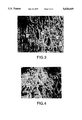
- FIG. 3 is a scanning electron micrograph (SEM) of a catalytic fiber employed in the present invention, enlarged 5,000 times;
- FIG. 4 is a microscopic photograph, enlarged 5:1, of a coherent catalytic filter material of the present invention comprising a mixture of catalyst loaded ePTFE fibers and untilled ePTFE fibers;
- FIG. 5 is a schematic representation of a tow fiber employed in the present invention.
- FIG. 6 is a cross-section schematic representation of one embodiment of a catalytic filter device of the present invention.
- FIG. 7 is a cross-section schematic representation of another embodiment of a catalytic filter device of the present invention.
- FIG. 8 is a cross-section schematic representation of still another embodiment of a catalytic filter device of the present invention.
- FIG. 9 is a cross-section schematic representation of yet another embodiment of a catalytic filter device of the present invention.
- FIG. 10 is cross-sectional view of a further embodiment of a filter device of the present invention.
- the current invention is an improved catalytic filter material.
- pollutant gas components such as NOx, Dioxin/Furan, CO, and others, can be catalytically altered (i.e., reduced or oxidized) into non-polluting or less polluting gas components.
- particulates in the gas stream can be separated and collected in the filter with high efficiencies.
- fluid in the present invention is intended to encompass any form of readily flowing material, including liquids and gases.
- FIGS. 1 through 3 show catalytic fibers 10 of the present invention at three different magnification levels.
- the fiber 10 comprises an expanded polytetrafluoroethylene (ePTFE) that is composed of polymeric nodes 12 and interconnecting fibrils 14.
- ePTFE expanded polytetrafluoroethylene
- FIGS. 1 through 3 show catalytic fibers 10 of the present invention at three different magnification levels.
- the fiber 10 comprises an expanded polytetrafluoroethylene (ePTFE) that is composed of polymeric nodes 12 and interconnecting fibrils 14.
- ePTFE expanded polytetrafluoroethylene
- Fibrils are intended to define small polymeric strands (such as, on the order of a few microns or less in diameter). "Nodes” are intended to define any structure attached to such fibrils, from relatively large polymer masses or particles (such as, up to 10 to 50 microns or more across) to mere intersect points of two or more fibrils.
- Expanded PTFE has a number of desirable properties that makes it particularly excellent filtration material.
- expanded PTFE material has many microscopic holes or "micropores" 16, such as on the order of 0.1 to 10 ⁇ m across, that allow gases to pass through but restricts the passage of larger materials, such as fine dust, etc.
- micropores such as on the order of 0.1 to 10 ⁇ m across
- pore size of the fibers may be varied dramatically within the scope of the present invention ranging from less than 0.05 ⁇ m to over 100 ⁇ m across.
- expanded PTFE has the demonstrated ability to be treated to selectively allow or restrict the passage of liquid water and/or water vapor.
- expanded PTFE is very strong and inert, allowing it to be used with a wide variety of materials and under a wide array of environmental conditions (including at temperatures up to about 260° C. continuous, and even up to 290° C. for short durations).
- the filter material of the present invention attaches catalytic particles directly to the microstructure of the expanded PTFE.
- particles of catalyst 18 are attached to and within the nodes and fibrils of the expanded PTFE.
- the catalytic particles 18 are introduced during the processing of the expanded PTFE itself so as to produce a stable microporous material with the particles securely attached to the fibrils 14 themselves.
- the surface of the catalyst particles is covered with a minimal amount of PTFE so as to maximize the reactivity of the catalyst.
- a catalytic filler is incorporated into an aqueous dispersion of dispersion-produced PTFE.
- the filler in small particle form is ordinarily less than 40 microns in size, and preferably less than 15 micron.
- particles is meant a material having any aspect ratio and thus includes flakes, fibers and spherical and nonspherical powders.
- suitable fillers for use in the present invention include: Noble (gold, silver, palladium, rhodium, etc. ) or non-noble metallic catalysts may be utilized.
- Noble gold, silver, palladium, rhodium, etc.
- non-noble metallic catalysts may be utilized.
- platinum a noble metal
- iron base ammonia decomposition catalyst iron chromium oxide mixtures
- zirconium promoted lanthanum cuprate zirconium promoted lanthanum cuprate
- the various oxides of copper, iron, vanadium, cobalt, molybdenum, manganese, and tungsten may be employed with the instant invention.
- the foregoing recitation is not meant to be exhaustive, rather, other suitable catalysts may be employed as well.
- reagent/catalyst include transition metal oxides of nickel, zinc; alumina (particular gamma phase) silicone, zirconium, chormium, ruthenium, tin, and alkalized alumina; alkali and alkaline earth oxides and carbonates; and minerals such as dawsonite, analcite, magnesioriebeckite, feldspars, alunite, anataso, azurite, bauxite, bunsanite, gothire, hematite, iron spinel, ilmenito, malachite, manganite, manganosite, mellite, siderite, and spinel.
- the filler is introduced prior to co-coagulation in an amount that will provide 1 to 99%, and preferably 30% to 90% by volume, solid-to-solid volume filler in the PTFE in relation to the final composite material (not including air content).
- the filled PTFE dispersion is then co-coagulated, usually by rapid stirring and the coagulated filled PTFE is dried.
- the filled material is then lubricated with a common paste extrusion lubricant, such as mineral spirits or glycols, and paste extruded.
- the extrudate is usually calendered, and then rapidly stretched to 1.2x to 5000x, preferably 2x to 100x, at a stretch rate of over 10% per second at a temperature of between 35° C. and 410° C.
- the lubricant can be removed from the extrudate prior to stretching, if desired.
- the catalyst-filled material of the present invention is formed into a felt.
- One suitable means of forming such a felt is in the following manner.
- a catalytically active ePTFE fiber is produced from a catalytic tape of ePTFE produced from a wet mixture of 1 to 99% by volume, preferably 30 to 90% by volume, catalyst (e.g., titanium dioxide catalyst from BASF, Ludwigshafen, Germany) and 99 to 1% by volume, preferably 70 to 10% by volume, PTFE resin (e.g., PTFE dispersion available from E. I. duPont de Nemours and Co., Wilmington, Del.).
- the tape is slit along its length into multiple strips, expanded, and processed over a rotating pinwheel to form a tow yarn.
- tow yarn 20 A representation of tow yarn 20 is shown in FIG. 5.
- a "spider web" of fine fibers 22 is formed that are connected together at random points 24 along the tow 20. This is accomplished by puling a catalyst-filled tape of PTFE through spiked pinwheels. By providing the pinwheels with a higher velocity than the speed of the tape, the material is slit to form the web structure shown. This process produces a very open structure with a high percentage of open and exposed surface area.
- the tow yarn is then chopped into short staple fibers.
- the staple fibers should be about 0.2 to 25 cm, preferably 2 to 12 cm (and especially about 5 cm) in length.
- the carded web is crosslapped onto a scrim and tacked together by a needle loom.
- the web is then crosslapped onto the other side of the scrim and needled again.
- the felt should be needle punched several times to interlock the staple fibers to the scrim sufficiently.
- This product may then be heat set while being restrained in the cross machine direction for several minutes to improve the thermal stability.
- the final felt preferably has a weight of approximately 300 to 3000 g/m 2 (with a weight of less than about 1500 g/m 2 generally preferred), an air permeability of approximately 4 to 60 m/min @11 mm water gauge, and a thickness of approximately 2 to 15 mm.
- the felt material may then be coated with an adhesive material.
- the adhesive material comprises a fiuorinated ethylene propylene copolymer (FEP) aqueous dispersion (e.g., T120 available from E. I. duPont de Nemours and Co.).
- FEP fiuorinated ethylene propylene copolymer
- Other lamination aids are PTFE dispersions, fluoropolymers, polyimides, sulfur (polyphenylene sulfide, etc.).
- the felt is then dried (e.g., in an oven at about 200° C.-250° C. for about 2 to 10 min).
- a layer of porous membrane may be laminated on the coated side of the felt.
- the preferred membrane comprises an expanded PTFE with an air permeability of about 0.3 to 200 m/min @12 mm water gauge. Preferred air permeability is about 6 m/min @12 mm water gauge.
- the felt is subjected to heat and pressure to soften the dried FEP aqueous dispersion.
- the resulting fabric laminate had good strength between the porous expanded PTFE membrane and the felt.
- the final material has an air permeability of about 1 to 10 m/min @12 mm water gauge with excellent filtration efficiency of solid particulates.
- a further improvement in this material is to form the felt from a combination of both catalyst filled material and another material.
- a staple fiber may be produced from an unfilled fiber of expanded porous PTFE.
- the catalytically active ePTFE fiber and the synthetic fiber of expanded porous PTFE may then be blended to form a hybrid mixture within a broad range of 100:1 to 1:100.
- the mixture comprises approximately 10:1 to 1:5 catalytic to noncatalytic by weight of the two staple fibers.
- a mixture of at least about 50% catalytic fiber is ideal.
- the blended hybrid mixture is then placed in a carding machine and processed in the manner described above.
- the final felt preferably has a weight of approximately 300 to 3000 g/m 2 , an air permeability of approximately 4 to 60 m/min @12 mm water gauge, and a thickness of approximately 2 to 15 mm. Following lamination, the final material has an air permeability of about 1 to 10 m/min @12 mm water gauge.
- FIG. 6 shows how a new filter 30 of the present can be made.
- a protective microporous membrane 32 is laminated to the catalytic filter material 34.
- dust particles 36 and adsorbed pollutants on these dust particles are blocked by the protective membrane 32 and cannot come into contact with the catalyst particles attached with the filter material 34.
- This provides significantly improved protection of the catalytic filter material 34 and vastly longer effective life for the filter 30.
- protective membranes 32 may be employed, it is particularly preferred to employ an expanded PTFE membrane due to its exceptional filtration properties. Additionally, an expanded PTFE membrane can be readily cleaned of accumulated contaminants, vastly increasing the operative life of the filter 30.
- the filter illustrated in FIG. 6 is particularly suited for use in treating pollutant gases and particulates therein.
- pollutants of NO, NO 2 , and NH 3 will readily be modified into H 2 O and N 2 .
- a filter 38 is shown having a catalytic filter layer 40, a porous protective layer 42, and a sorptive layer 44.
- the sorptive layer 44 can be mounted either upstream or downstream of the protective membrane 42 or the catalytic filter layer 40. In most cases it is preferred that the sorptive layer 44 be mounted between the protective membrane 42 and the catalytic filter layer 40, as shown.
- the sorptive layer 44 serves to absorb or adsorb other poisons and pollutants in the fluid stream. This layer may be formed from any suitable sorptive material, including carbon filled felt or weaves, etc.
- the catalytic filter of the present invention may be combined with other filter components with additional beneficial results. For instance, if other gas components threaten to poison the catalytic filter layer, a further protective catalytic layer may be inserted anywhere upstream of the catalytic layer, as is shown in FIG. 8.
- the filter unit 46 of FIG. 8 employs a first catalytic layer 48 and a second catalytic layer 50. Although not always necessary, it may be desirable to include a layer of material 52 between the two layers 48, 50 to isolate the layers from each other and/or to provide some other function (e.g., scrim, absorption, liquid separation, further catalytic function, etc.) Again, a protective layer 54 and sorptive layer 56 are provided upstream.
- the two filter layers 48, 50 may use identical or similar catalytic materials, it is contemplated to be particularly useful to provide different catalytic layers so as to improve the overall functioning of the filter. For instance, while one catalytic layer may catalytically reduce NO x , the other could catalytically oxidize CO to CO 2 . In addition, a second or third layer could adsorb SO 3 which poisons some of the other catalysts.
- FIG. 9 illustrates a further example of how multiple layers of filtration material can be combined in the filter device of the present invention.
- the filter device 58 comprises a first protective layer 60, a sorptive layer 62, a catalytic layer 64, a sorptive layer 66, and a second protective layer 68.
- the sorptive layer 66 is preferably one that can absorb or adsorb undesirable materials from the fluid stream before it exits the filter device, such as a carbon-filled polymer.
- the use of a second protective layer 68 is believed to provide better containment and protection of the active layers within the filter device 58 and to provide resistance to distortion of the filter device when it is place in a strong fluid stream or in direct contact with filter support materials such as filter cages.
- the second protective layer 68 should be constructed from a strong, porous, and abrasion-resistant material, such as a polymer felt or mesh.
- the filter device 70 comprises a first protective layer 72, a support layer 74, and an integrated layer 76 that includes a catalytic layer portion 78, an absorptive layer portion 80, and a protective layer portion 82.
- the integrated layer 76 essentially combines the protective layer and the active layers 78, 80 into a coherent unit. Preferably, such combination is accomplished by forming the protective layer in a scrim needled punched to form a felt of catalytic fibers.
- the absorptive layer 80 may likewise be combined into the felt, such as in the form of a needled punched filled membrane, filled fibers, loose absorptive material, etc.
- this integrated layer 76 may be constructed of only the catalytic layer 78 and the protective layer 82, with the absorptive layer 80 not used or applied separately.
- filter apparatus there are numerous permutations of filter apparatus that can be made in accordance with the present invention.
- combinations of material contemplated by the present invention are: (1) using catalytic felt alone; (2) covering catalytic felt with one or more covers of particle filtration material (such as, untilled microporous PTFE membrane); (3) covering the catalytic felt with one or more covers of other filtration material (such as microporous PTFE filled with one or more kinds of catalytic material; (4) covering the catalytic felt with two or more covers of different constructions, such as two different covers, each providing a different catalytic material; (5) constructing a filter apparatus with multiple layers of catalytic felt (with similar or different construction); or (6) combining any of these or other filter constructions.
- the different layers may be mounted by lamination felting, needle felting, or without binding mechanism.
- the coagulum was dried in a convection oven with a maximum temperature of about 165° C. for 24 hours.
- the material dried in small, cracked cakes approximately 2 cm thick and was chilled to below 0° C.
- the chilled cake was hand-ground using a tight, circular motion and minimal downward force through a 0.635 cm mesh stainless steel screen, then 0.64 g of mineral spirits per gram of powder was added.
- the mixture was chilled and tumbled for 5 minutes, then allowed to sit at 25° C. overnight and was rerumbled for 5 minutes.
- a pellet was formed in a cylinder by pulling a vacuum and pressing at 853 psi. The pellet was then heated to 49° C. in a sealed tube. The pellet was then extruded into a 6" ⁇ 0.080" tape form. The tape was then calendered through rolls to a thickness of 0.020 inch. The lubricant was evaporated by running the tape across heated rolls. The tape was stretched in the machine direction at a 2 to 1 ratio, 270° C., 105 ft/min. A thin porous tape was produced with a porosity of approximately 84% and a final thickness of about 10 mils.
- a felt of the present invention was produced in the following manner.
- a catalytic active ePTFE fiber was produced from a catalytic tape of ePTFE produced from a wet mixture of 50% by volume titanium dioxide catalyst (completed from BASF O-85) and 50% PTFE resin (duPont) in accordance with the steps outlined in Example 1, above.
- the tape was slit along its length into three strips, expanded, and processed over a rotating pinwheel to form a tow yarn.
- the tow yarn was then chopped to 5 cm length staple fiber.
- a similar staple was also produced from a synthetic fiber of expanded porous PTFE.
- the catalytically active ePTFE fiber and the synthetic fiber of expanded porous PTFE were opened in a shear air field and then collected in boxes for additional processing.
- a blend of the two staple fibers was then produced by hand carding (mixing) 50% by weight catalytic ePTFE fiber and 50% by weight synthetic fiber.
- the hand carded filter material was determined to be catalytically active and has a removal efficiency for NO 2 of over 80%.
- a woven scrim is made out of 440 decitex ePTFE weaving fiber, (RASTEX® fiber, available from W. L. Gore and Associates, Inc., Elkton, Md.).
- the scrim is constructed with a thread count of 16 ⁇ 8 threads/cm resulting a weight of approximately 130 g/m 2 .
- the needle felt is coated with a fluorinated ethylene propylene copolymer (FEP) aqueous dispersion (T120 available from E. I. duPont de Nemours and Co.).
- FEP fluorinated ethylene propylene copolymer
- T120 available from E. I. duPont de Nemours and Co.
- the felt is then dried in loop dryer oven at 200° C. with a dwell time of 8 min.
- the dried aqueous dispersion add on is 3.5% by weight.
- a layer of porous expanded PTFE membrane with an air permeability of 8.8 m/min @20 mm water gauge is laminated to the coated side of the felt.
- the felt is subject to sufficient heat, pressure, and dwell time to soften the dried FEP aqueous dispersion.
- the resulting fabric laminate had good strength between the porous expanded PTFE membrane and the felt, and an air permeability of 2.8 m/min @12 mm water gauge with excellent filtration efficiency of solid particulates.
- the inventive nonwoven fabric laminate is tested to determine its catalytic gas removal efficiencies.
- the current invention can be used in many flue gas cleaning processes especially to clean emissions of stationary sources.
- the filter material can be used to make filter devices such as filter bags or cartridges. In most cases these filters have to collect substantial amounts of dust that is generated in the combustion process. After short collection times between 1 and 60 minutes the collected dust layer on the dirty side of the filter material increases the pressure drop across the filter and the filter has to be cleaned. During this cleaning cycle that involves a high energy input into the filter the outer dust layer falls off and a new particulate filtration cycle can begin. The catalytic conversion of pollutant gases will continue uninterrupted.
- Most catalytic filter materials that have been proposed to date consist of a regular woven or non-woven filter material in which the catalytically active particles are inserted as a foreign body.
- the catalyst particles are an integral part of the filter material and have no negative effects on the lifetime of the filter material.
- all particle insertion devices have the disadvantage that they increase the pressure drop of the filter material and can get in contact with catalyst polluting dusts.
- the catalyst particles do not interfere with the particle filtration process at all and can not be deactivated by the pollutant dusts.
- the present invention allows for the ready combination of filtration and catalytic functions, presently performed by separate apparatus, into a single easily employed unit.
- the current catalyst works well at temperatures of 150° to 250° C. and preferably between 200° and 250° C.
Landscapes
- Chemical & Material Sciences (AREA)
- Chemical Kinetics & Catalysis (AREA)
- Engineering & Computer Science (AREA)
- Organic Chemistry (AREA)
- Environmental & Geological Engineering (AREA)
- Materials Engineering (AREA)
- General Chemical & Material Sciences (AREA)
- Oil, Petroleum & Natural Gas (AREA)
- Textile Engineering (AREA)
- Health & Medical Sciences (AREA)
- Analytical Chemistry (AREA)
- Biomedical Technology (AREA)
- Catalysts (AREA)
- Filtering Materials (AREA)
- Exhaust Gas Treatment By Means Of Catalyst (AREA)
- Woven Fabrics (AREA)
- Laminated Bodies (AREA)
- Nonwoven Fabrics (AREA)
Priority Applications (14)
| Application Number | Priority Date | Filing Date | Title |
|---|---|---|---|
| US08/515,195 US5620669A (en) | 1995-08-15 | 1995-08-15 | Catalytic filter material and method of making same |
| ES96919284T ES2259796T3 (es) | 1995-08-15 | 1996-06-07 | Material filtrante catalitico y procedimiento de fabricacion del mismo. |
| DK96919284T DK0854751T3 (da) | 1995-08-15 | 1996-06-07 | Katalytisk filtermateriale og fremgangsmåde til fremstilling deraf |
| JP50925597A JP3618761B2 (ja) | 1995-08-15 | 1996-06-07 | 触媒フィルター材料とその製造方法 |
| EP96919284A EP0854751B1 (en) | 1995-08-15 | 1996-06-07 | Catalytic filter material and method of making same |
| PT96919284T PT854751E (pt) | 1995-08-15 | 1996-06-07 | Material de filtro catalitico e metodo para produzir o mesmo |
| AU61659/96A AU703305B2 (en) | 1995-08-15 | 1996-06-07 | Catalytic filter material and method of making same |
| CA002228597A CA2228597C (en) | 1995-08-15 | 1996-06-07 | Catalytic filter material and method of making same |
| PCT/US1996/009760 WO1997006877A1 (en) | 1995-08-15 | 1996-06-07 | Catalytic filter material and method of making same |
| DE69636038T DE69636038T2 (de) | 1995-08-15 | 1996-06-07 | Katalytisches filtermaterial und herstellungsverfahren |
| AT96919284T ATE322938T1 (de) | 1995-08-15 | 1996-06-07 | Katalytisches filtermaterial und herstellungsverfahren |
| US08/786,589 US5843390A (en) | 1995-08-15 | 1997-01-21 | Method of using a catalytic filter |
| AU18351/99A AU1835199A (en) | 1995-08-15 | 1999-02-23 | Catalytic filter material and method of making same |
| JP2002278921A JP2003190721A (ja) | 1995-08-15 | 2002-09-25 | 触媒フィルター材料とその製造方法 |
Applications Claiming Priority (1)
| Application Number | Priority Date | Filing Date | Title |
|---|---|---|---|
| US08/515,195 US5620669A (en) | 1995-08-15 | 1995-08-15 | Catalytic filter material and method of making same |
Related Child Applications (1)
| Application Number | Title | Priority Date | Filing Date |
|---|---|---|---|
| US08/786,589 Continuation US5843390A (en) | 1995-08-15 | 1997-01-21 | Method of using a catalytic filter |
Publications (1)
| Publication Number | Publication Date |
|---|---|
| US5620669A true US5620669A (en) | 1997-04-15 |
Family
ID=24050340
Family Applications (2)
| Application Number | Title | Priority Date | Filing Date |
|---|---|---|---|
| US08/515,195 Expired - Lifetime US5620669A (en) | 1995-08-15 | 1995-08-15 | Catalytic filter material and method of making same |
| US08/786,589 Expired - Lifetime US5843390A (en) | 1995-08-15 | 1997-01-21 | Method of using a catalytic filter |
Family Applications After (1)
| Application Number | Title | Priority Date | Filing Date |
|---|---|---|---|
| US08/786,589 Expired - Lifetime US5843390A (en) | 1995-08-15 | 1997-01-21 | Method of using a catalytic filter |
Country Status (11)
| Country | Link |
|---|---|
| US (2) | US5620669A (da) |
| EP (1) | EP0854751B1 (da) |
| JP (2) | JP3618761B2 (da) |
| AT (1) | ATE322938T1 (da) |
| AU (1) | AU703305B2 (da) |
| CA (1) | CA2228597C (da) |
| DE (1) | DE69636038T2 (da) |
| DK (1) | DK0854751T3 (da) |
| ES (1) | ES2259796T3 (da) |
| PT (1) | PT854751E (da) |
| WO (1) | WO1997006877A1 (da) |
Cited By (54)
| Publication number | Priority date | Publication date | Assignee | Title |
|---|---|---|---|---|
| US5755962A (en) * | 1996-11-26 | 1998-05-26 | Isp Investments Inc. | Filter bag and process of manufacture |
| DE19720981A1 (de) * | 1997-05-20 | 1998-11-26 | Abb Research Ltd | Filteranordnung |
| US5843390A (en) * | 1995-08-15 | 1998-12-01 | W. L. Gore & Associates, Inc. | Method of using a catalytic filter |
| US6196708B1 (en) * | 1998-05-14 | 2001-03-06 | Donaldson Company, Inc. | Oleophobic laminated articles, assemblies of use, and methods |
| WO2001021284A1 (en) * | 1999-09-22 | 2001-03-29 | Gore Enterprise Holdings, Inc. | Chemically active filter material |
| WO2002049759A1 (de) * | 2000-12-21 | 2002-06-27 | Basf Aktiengesellschaft | Partikel-faser-agglomerate |
| US20030024686A1 (en) * | 2001-07-12 | 2003-02-06 | Ouellette Joseph P. | Biomass heating system |
| US20040074391A1 (en) * | 2002-10-16 | 2004-04-22 | Vincent Durante | Filter system |
| US6811721B1 (en) | 2003-05-30 | 2004-11-02 | E. I. Du Pont De Nemours And Company | Composition and method for reduction of persistent bio-accumulative and toxic pollutants in carbochlorination processes |
| US20050019240A1 (en) * | 2003-06-20 | 2005-01-27 | Xiao-Chun Lu | Flue gas purification process using a sorbent polymer composite material |
| US20060159605A1 (en) * | 2005-01-10 | 2006-07-20 | The University Of North Dakota | Mercury oxidation of flue gas using catalytic barrier filters |
| US20060272499A1 (en) * | 2005-06-03 | 2006-12-07 | Daramic Llc | Gas filtration media |
| US20070140928A1 (en) * | 2005-12-16 | 2007-06-21 | Beall Douglas M | Low pressure drop coated diesel exhaust filter |
| US20080166938A1 (en) * | 2007-01-09 | 2008-07-10 | Teadit Industria E Comercio Ltda. | Microfiber split film filter felt and method of making same |
| CN100447317C (zh) * | 2006-11-30 | 2008-12-31 | 浙江理工大学 | 用于废气分解的膨体聚四氟乙烯纤维的制备方法 |
| CN100488610C (zh) * | 2007-07-10 | 2009-05-20 | 浙江理工大学 | 高温烟气和粉尘处理用的聚四氟乙烯微孔薄膜制备方法 |
| US20090155564A1 (en) * | 2007-09-28 | 2009-06-18 | General Electric Company | Article and associated method |
| US20090235625A1 (en) * | 2007-09-28 | 2009-09-24 | General Electric Company | Filter and associated method |
| US20100095843A1 (en) * | 2008-10-22 | 2010-04-22 | Gebert Richard E | Air Pollution Control Filter Elements for Filtration Systems |
| CN101255615B (zh) * | 2008-04-08 | 2010-06-02 | 浙江理工大学 | 有催化分解二恶英功能的膨体聚四氟乙烯纤维的制备方法 |
| CN101580973B (zh) * | 2009-04-23 | 2011-02-02 | 浙江理工大学 | 一种具有二恶英分解功能的聚四氟乙烯纤维的制备方法 |
| WO2011022586A1 (en) * | 2009-08-21 | 2011-02-24 | Engineered Materials, Inc. | Dynamic inks and coatings |
| CN102698740A (zh) * | 2012-06-29 | 2012-10-03 | 南京工业大学 | 一种袋式脱除NOx催化剂及其制备方法 |
| US8323675B2 (en) | 2004-04-20 | 2012-12-04 | Genzyme Corporation | Soft tissue prosthesis for repairing a defect of an abdominal wall or a pelvic cavity wall |
| WO2013019393A1 (en) * | 2011-07-29 | 2013-02-07 | Flsmidth A/S | Pollution control system for kiln exhaust |
| US20140263026A1 (en) * | 2013-03-15 | 2014-09-18 | Hayward Industries, Inc. | Filtration Media and Filter Therefor |
| US20150182898A1 (en) * | 2013-12-31 | 2015-07-02 | Bha Altair, Llc | Ridgid porous plastic filters incorporating polymeric particles and polymeric fibers |
| CN104941316A (zh) * | 2015-06-05 | 2015-09-30 | 南通大学 | 一种具有no催化分解能力的烟尘过滤材料的制备方法 |
| CN104971704A (zh) * | 2015-07-09 | 2015-10-14 | 常州大学 | 一种用于汽车尾气处理的吸附材料 |
| CN105013249A (zh) * | 2015-07-02 | 2015-11-04 | 辽宁鸿盛环境技术集团股份有限公司 | 一种脱硝和二噁英的pps复合毡功能滤料及其制备方法 |
| WO2017106730A1 (en) | 2015-12-17 | 2017-06-22 | W. L. Gore & Associates, Inc. | Catalytic filter material |
| CN107961619A (zh) * | 2017-12-11 | 2018-04-27 | 项朝卫 | 多功能覆膜滤料的制备方法 |
| US20180117202A1 (en) * | 2016-11-03 | 2018-05-03 | Weiming Gao | Reactivatable air purification pad with molecular sieves and process |
| CN108698026A (zh) * | 2016-03-07 | 2018-10-23 | 托普索公司 | 具有低压降的催化的织物过滤器的方法 |
| CZ307624B6 (cs) * | 2013-05-10 | 2019-01-23 | Technická univerzita v Liberci | Kompozitní materiál pro filtraci spalin a způsob vytvoření tohoto materiálu |
| WO2019099025A1 (en) | 2017-11-17 | 2019-05-23 | W. L. Gore & Associates, Inc. | Multilayer composite with catalytic mixed matrix membrane layer |
| TWI675694B (zh) * | 2014-03-21 | 2019-11-01 | 丹麥商托普索公司 | 過濾袋裝配 |
| US20200030731A1 (en) * | 2018-07-26 | 2020-01-30 | Molekule Inc. | Fluid filtration system and method of use |
| US10584886B2 (en) | 2017-10-17 | 2020-03-10 | Molekule, Inc. | System and method for photoelectrochemical air purification |
| US10625207B2 (en) | 2017-11-01 | 2020-04-21 | Molekule, Inc. | System for photoelectrochemical air purification |
| US10940471B1 (en) * | 2019-10-30 | 2021-03-09 | W. L. Gore & Associates, Inc. | Catalytic efficiency of flue gas filtration |
| USD912793S1 (en) | 2017-05-23 | 2021-03-09 | Molekule, Inc. | Air purifier |
| US11071947B2 (en) | 2019-10-30 | 2021-07-27 | W. L. Gore & Associates, Inc. | Catalytic efficiency of flue gas filtration |
| WO2021158697A1 (en) * | 2020-02-03 | 2021-08-12 | Molekule, Inc. | Filter media and system and method for manufacture thereof |
| US11224853B2 (en) | 2018-04-11 | 2022-01-18 | W. L. Gore & Associates, Inc. | Metal supported powder catalyst matrix and processes for multiphase chemical reactions |
| US11596900B2 (en) | 2020-08-31 | 2023-03-07 | Molekule, Inc. | Air filter and filter media thereof |
| US20230294032A1 (en) * | 2020-07-15 | 2023-09-21 | W. L. Gore & Associates, Inc. | Methods for regenerating a filter medium and cleaning flue gas |
| USD1001257S1 (en) | 2020-07-29 | 2023-10-10 | Molekule, Inc. | Filtration device |
| US12251481B2 (en) | 2020-06-05 | 2025-03-18 | Molekule, Inc. | Photocatalytic fluid filtration system and method |
| WO2025106714A1 (en) * | 2023-11-15 | 2025-05-22 | Donaldson Company, Inc. | Porous non-woven ptfe compositions and methods of forming |
| WO2025106709A1 (en) * | 2023-11-15 | 2025-05-22 | Donaldson Company, Inc. | Expanded ptfe compositions and methods of forming |
| WO2025106700A1 (en) * | 2023-11-15 | 2025-05-22 | Donaldson Company, Inc. | Ptfe and active particle compositions |
| US12343680B2 (en) | 2020-01-17 | 2025-07-01 | Molekule Group, Inc. | Fluid filtration system and method of use |
| TWI912920B (zh) * | 2024-09-12 | 2026-01-21 | 富利康科技股份有限公司 | 觸媒濾布袋 |
Families Citing this family (21)
| Publication number | Priority date | Publication date | Assignee | Title |
|---|---|---|---|---|
| US6136412A (en) * | 1997-10-10 | 2000-10-24 | 3M Innovative Properties Company | Microtextured catalyst transfer substrate |
| US5989709A (en) * | 1998-04-30 | 1999-11-23 | Gore Enterprises Holdings, Inc. | Polytetrafluoroethylene fiber |
| US6517612B1 (en) | 2001-10-29 | 2003-02-11 | Gore Enterprise Holdings, Inc. | Centrifugal filtration device |
| US8187733B2 (en) * | 2005-08-02 | 2012-05-29 | W. L. Gore & Associates, Inc. | Architectural fabric |
| CN102814080A (zh) | 2006-02-13 | 2012-12-12 | 唐纳森公司 | 包括细纤维和反应、吸附或吸收颗粒的过滤网 |
| US7837756B2 (en) | 2007-04-05 | 2010-11-23 | Aaf-Mcquay Inc. | Filter with ePTFE and method of forming |
| ITMI20070750A1 (it) * | 2007-04-13 | 2008-10-14 | Dulevo Int Spa | Macchina spazzatrice includente un dispositivo filtrante perfezionato |
| US8673040B2 (en) | 2008-06-13 | 2014-03-18 | Donaldson Company, Inc. | Filter construction for use with air in-take for gas turbine and methods |
| US8728401B2 (en) * | 2008-10-27 | 2014-05-20 | Sefar BDH, Inc. | Filter bag, pleatable filtration material therefore, and process of making same |
| JP5455407B2 (ja) * | 2009-03-25 | 2014-03-26 | 日本ゴア株式会社 | 触媒粒子を担持した延伸ポリテトラフルオロエチレン多孔質膜またはテープの製造方法およびオゾン除去用フィルタ |
| US20110146493A1 (en) * | 2009-12-22 | 2011-06-23 | General Electric Company | Filter bag and laminated filter media |
| CN102091658B (zh) * | 2010-12-27 | 2013-07-10 | 北京工业大学 | 一种防粉尘粘附的包裹脱硝催化球及其制备方法 |
| US9181888B2 (en) | 2013-10-28 | 2015-11-10 | Cummins Inc. | Selectively trapping and storing SO3 in an exhaust gas effluent |
| CN103820999A (zh) * | 2014-02-27 | 2014-05-28 | 江苏东方滤袋有限公司 | 一种袋式除尘材料的整理方法及制得的除尘材料 |
| CN106731238A (zh) * | 2017-02-28 | 2017-05-31 | 武汉科技大学 | 一种具有催化功能的聚四氟乙烯滤料的生产方法 |
| JPWO2018174137A1 (ja) * | 2017-03-24 | 2020-01-23 | 東レ株式会社 | 濾材およびバグフィルター |
| KR101971645B1 (ko) * | 2018-06-29 | 2019-04-23 | 한국기계연구원 | 플레이크 형상의 분말 코팅층을 포함하는 필터 및 이의 제조방법 |
| CN109603310A (zh) * | 2018-12-07 | 2019-04-12 | 江苏通盛滤袋有限公司 | 一种耐化学腐蚀覆膜针刺毡 |
| CN113677422B (zh) * | 2019-04-12 | 2024-02-02 | W.L.戈尔及同仁股份有限公司 | 大颗粒高性能催化带 |
| CN113733699B (zh) * | 2021-09-03 | 2023-04-11 | 天台宏辉过滤科技有限公司 | 一种自洁性液体过滤布及制备方法 |
| KR102478940B1 (ko) * | 2021-11-30 | 2022-12-19 | 주식회사 마이크로원 | Ptfe 파이버 제조 방법 및 이를 이용한 ptfe 멤브레인 촉매필터 |
Citations (50)
| Publication number | Priority date | Publication date | Assignee | Title |
|---|---|---|---|---|
| US3925248A (en) * | 1971-05-11 | 1975-12-09 | Collo Rheincollodium Koln Gmbh | Filter medium for gases |
| DE2537671A1 (de) * | 1974-09-18 | 1976-04-08 | Corning Glass Works | Verfahren zur regenerierung von enzymtraegern |
| US3953566A (en) * | 1970-05-21 | 1976-04-27 | W. L. Gore & Associates, Inc. | Process for producing porous products |
| US3962153A (en) * | 1970-05-21 | 1976-06-08 | W. L. Gore & Associates, Inc. | Very highly stretched polytetrafluoroethylene and process therefor |
| JPS5289560A (en) * | 1976-01-23 | 1977-07-27 | Mitsui Toatsu Chem Inc | Removal of nitrogen oxides |
| US4042352A (en) * | 1975-04-22 | 1977-08-16 | Sumitomo Chemical Company, Limited | Method for the removal of the dusts from combustion exhaust gases |
| JPS5298674A (en) * | 1976-02-13 | 1977-08-18 | Kobe Steel Ltd | Denitration apparatus for exhasut gas |
| US4053557A (en) * | 1973-05-14 | 1977-10-11 | Mitsubishi Chemical Industries Ltd. | Method of decomposing chlorohydrocarbons |
| US4096227A (en) * | 1973-07-03 | 1978-06-20 | W. L. Gore & Associates, Inc. | Process for producing filled porous PTFE products |
| GB2015543A (en) * | 1977-06-30 | 1979-09-12 | Exxon Research Engineering Co | Sizing and shaping of catalysts |
| US4220633A (en) * | 1979-04-30 | 1980-09-02 | The Babcock & Wilcox Company | Filter house and method for simultaneously removing NOx and particulate matter from a gas stream |
| US4259209A (en) * | 1978-04-28 | 1981-03-31 | Rikagaku Kenkyusho | Catalyst for concentrating hydrogen isotopes and process for producing a support therefor |
| JPS5651230A (en) * | 1979-10-04 | 1981-05-08 | Mitsubishi Heavy Ind Ltd | Cleaning method for combustion waste gas |
| US4309386A (en) * | 1979-04-30 | 1982-01-05 | The Babcock & Wilcox Company | Filter house having catalytic filter bags for simultaneously removing NOx and particulate matter from a gas stream |
| US4332698A (en) * | 1981-01-19 | 1982-06-01 | Mpd Technology Corporation | Catalyst sheet and preparation |
| US4358396A (en) * | 1981-01-19 | 1982-11-09 | Mpd Technology Corporation | Particulate catalyst and preparation |
| US4518705A (en) * | 1980-10-31 | 1985-05-21 | Eltech Systems Corporation | Three layer laminate |
| DE3404277A1 (de) * | 1984-02-08 | 1985-08-08 | Metallgesellschaft Ag, 6000 Frankfurt | Dampferzeugungsanlage mit abgasreinigungseinrichtung |
| DE3604946A1 (de) * | 1986-02-17 | 1986-07-31 | Mehdi Haji Dr.-Ing. 7259 Friolzheim Javad | Verfahren und anlagen zur reinigung von rauchgasen |
| US4728503A (en) * | 1984-11-02 | 1988-03-01 | Mitsubishi Jukogyo Kabushiki Kaisha | Filter medium for treating an exhaust gas |
| US4732879A (en) * | 1985-11-08 | 1988-03-22 | Owens-Corning Fiberglas Corporation | Method for applying porous, metal oxide coatings to relatively nonporous fibrous substrates |
| DE3633214A1 (de) * | 1986-09-30 | 1988-03-31 | Siemens Ag | Rauchgasleitung mit einer einrichtung zur minderung der stickoxide |
| DE3642179A1 (de) * | 1986-12-10 | 1988-06-23 | Hoelter Heinz | Verfahren und vorrichtung zur simultanen so(pfeil abwaerts)2(pfeil abwaerts)- und no(pfeil abwaerts)x(pfeil abwaerts)-abscheidung hinter feuerungsanlagen mit koks-precoat-filter-system |
| US4793981A (en) * | 1986-11-19 | 1988-12-27 | The Babcock & Wilcox Company | Integrated injection and bag filter house system for SOx -NOx -particulate control with reagent/catalyst regeneration |
| US4833877A (en) * | 1986-09-02 | 1989-05-30 | Bergwerksverband Gmbh | Process for the reduction of pollutant emissions from power stations with combined gas/steam turbine processes with preceding coal gasification |
| US4916110A (en) * | 1988-11-01 | 1990-04-10 | W. L. Gore & Associates, Inc. | Microporous catalytic material and support structure |
| WO1990011817A1 (en) * | 1989-04-07 | 1990-10-18 | ABB Fläkt AB | Method for cleaning flue gas formed on refuse incineration |
| US4983434A (en) * | 1989-04-07 | 1991-01-08 | W. L. Gore & Associates, Inc. | Filter laminates |
| US5000624A (en) * | 1987-09-04 | 1991-03-19 | Ransburg-Gema Ag | Powder preparation system for coating powder |
| US5051391A (en) * | 1988-04-08 | 1991-09-24 | Mitsubishi Jukogyo Kabushiki Kaisha | Catalyst filter and method for manufacturing a catalyst filter for treating a combustion exhaust gas |
| US5064792A (en) * | 1989-02-27 | 1991-11-12 | Eka Nobel Ab | Catalyst for the reduction of nitrogen oxides, a method for its preparation and the use thereof |
| EP0457480A1 (en) * | 1990-05-12 | 1991-11-21 | Johnson Matthey Public Limited Company | Catalytic reduction |
| JPH03277367A (ja) * | 1990-03-27 | 1991-12-09 | Daikin Ind Ltd | オゾン脱臭機 |
| JPH0429720A (ja) * | 1990-05-25 | 1992-01-31 | Takeda Chem Ind Ltd | ガスの処理法 |
| DE4025052A1 (de) * | 1990-08-07 | 1992-02-13 | Siemens Ag | Verfahren und einrichtung zur entnahme von rauchgas |
| JPH04235718A (ja) * | 1991-01-11 | 1992-08-24 | Japan Vilene Co Ltd | オゾン分解用シート |
| JPH0515782A (ja) * | 1991-07-08 | 1993-01-26 | Sekiyu Sangyo Kasseika Center | 窒素酸化物接触還元用触媒 |
| US5262234A (en) * | 1991-10-17 | 1993-11-16 | W. L. Gore & Associates, Inc. | Polyetrafluoroethylene fiber containing conductive filler |
| EP0569877A1 (de) * | 1992-05-12 | 1993-11-18 | Degussa Aktiengesellschaft | Tieftemperatur-Entstickung von Rauchgasen |
| DE4216772A1 (de) * | 1992-05-21 | 1993-12-16 | Ftu Forschung Und Tech Entwick | Verfahren zur Reinigung von Gasen und Abgasen mit Oxidationsmitteln |
| JPH06334A (ja) * | 1992-06-16 | 1994-01-11 | Kurabo Ind Ltd | 除塵脱硝フィルター |
| EP0470659B1 (de) * | 1990-08-04 | 1994-04-13 | METALLGESELLSCHAFT Aktiengesellschaft | Verfahren zur Abtrennung von Staub und organischen Verbindungen aus Abgasen |
| US5304362A (en) * | 1989-11-20 | 1994-04-19 | Abb Carbon Ab | Method in cleaning flue gas in a PFBC plant including a gas turbine driven thereby |
| US5324579A (en) * | 1991-12-18 | 1994-06-28 | W. L. Gore & Associates, Inc. | Static dissipative nonwoven textile material |
| US5342434A (en) * | 1992-12-14 | 1994-08-30 | W. L. Gore & Associates, Inc. | Gas permeable coated porous membranes |
| NL9301807A (nl) * | 1993-10-19 | 1995-05-16 | Akoestikon Geluidsisolatie B V | Bouwelement, geschikt voor het vormen van een regelconstructie waartegen een beplating bevestigd kan worden. |
| US5417743A (en) * | 1994-01-21 | 1995-05-23 | W. L. Gore & Associates, Inc. | Self-adhesive vent filter and adsorbent assembly with a diffusion tube |
| US5437900A (en) * | 1991-06-14 | 1995-08-01 | W. L. Gore & Associates, Inc. | Surface modified porous expanded polytetrafluoroethylene and process for making |
| US5496396A (en) * | 1992-02-04 | 1996-03-05 | W. L. Gore & Associates (Uk) Ltd. | Gas filter |
| US5500038A (en) * | 1994-08-30 | 1996-03-19 | W. L. Gore & Associates, Inc. | Non-particulating compact adsorbent filter |
Family Cites Families (5)
| Publication number | Priority date | Publication date | Assignee | Title |
|---|---|---|---|---|
| DD253767A1 (de) * | 1986-11-24 | 1988-02-03 | Tech Hochschule C Schorlemmer | Verfahren zur entfernung von stickstoffoxiden aus abgasen |
| US5221484A (en) * | 1991-01-10 | 1993-06-22 | Ceramem Separations Limited Partnership | Catalytic filtration device and method |
| DE4303610A1 (de) * | 1993-02-09 | 1994-08-11 | Studiengesellschaft Kohle Mbh | Verfahren zur Herstellung von vergiftungsfesten Katalysatoren |
| US5599614A (en) * | 1995-03-15 | 1997-02-04 | W. L. Gore & Associates, Inc. | Integral composite membrane |
| US5620669A (en) * | 1995-08-15 | 1997-04-15 | W. L. Gore & Associates, Inc. | Catalytic filter material and method of making same |
-
1995
- 1995-08-15 US US08/515,195 patent/US5620669A/en not_active Expired - Lifetime
-
1996
- 1996-06-07 EP EP96919284A patent/EP0854751B1/en not_active Expired - Lifetime
- 1996-06-07 JP JP50925597A patent/JP3618761B2/ja not_active Expired - Lifetime
- 1996-06-07 DK DK96919284T patent/DK0854751T3/da active
- 1996-06-07 AT AT96919284T patent/ATE322938T1/de active
- 1996-06-07 PT PT96919284T patent/PT854751E/pt unknown
- 1996-06-07 WO PCT/US1996/009760 patent/WO1997006877A1/en not_active Ceased
- 1996-06-07 AU AU61659/96A patent/AU703305B2/en not_active Expired
- 1996-06-07 DE DE69636038T patent/DE69636038T2/de not_active Expired - Lifetime
- 1996-06-07 CA CA002228597A patent/CA2228597C/en not_active Expired - Lifetime
- 1996-06-07 ES ES96919284T patent/ES2259796T3/es not_active Expired - Lifetime
-
1997
- 1997-01-21 US US08/786,589 patent/US5843390A/en not_active Expired - Lifetime
-
2002
- 2002-09-25 JP JP2002278921A patent/JP2003190721A/ja not_active Withdrawn
Patent Citations (53)
| Publication number | Priority date | Publication date | Assignee | Title |
|---|---|---|---|---|
| US3953566A (en) * | 1970-05-21 | 1976-04-27 | W. L. Gore & Associates, Inc. | Process for producing porous products |
| US3962153A (en) * | 1970-05-21 | 1976-06-08 | W. L. Gore & Associates, Inc. | Very highly stretched polytetrafluoroethylene and process therefor |
| US4187390A (en) * | 1970-05-21 | 1980-02-05 | W. L. Gore & Associates, Inc. | Porous products and process therefor |
| US3925248A (en) * | 1971-05-11 | 1975-12-09 | Collo Rheincollodium Koln Gmbh | Filter medium for gases |
| US4053557A (en) * | 1973-05-14 | 1977-10-11 | Mitsubishi Chemical Industries Ltd. | Method of decomposing chlorohydrocarbons |
| US4096227A (en) * | 1973-07-03 | 1978-06-20 | W. L. Gore & Associates, Inc. | Process for producing filled porous PTFE products |
| DE2537671A1 (de) * | 1974-09-18 | 1976-04-08 | Corning Glass Works | Verfahren zur regenerierung von enzymtraegern |
| US4042352A (en) * | 1975-04-22 | 1977-08-16 | Sumitomo Chemical Company, Limited | Method for the removal of the dusts from combustion exhaust gases |
| JPS5289560A (en) * | 1976-01-23 | 1977-07-27 | Mitsui Toatsu Chem Inc | Removal of nitrogen oxides |
| JPS5298674A (en) * | 1976-02-13 | 1977-08-18 | Kobe Steel Ltd | Denitration apparatus for exhasut gas |
| GB2015543A (en) * | 1977-06-30 | 1979-09-12 | Exxon Research Engineering Co | Sizing and shaping of catalysts |
| US4259209A (en) * | 1978-04-28 | 1981-03-31 | Rikagaku Kenkyusho | Catalyst for concentrating hydrogen isotopes and process for producing a support therefor |
| US4309386A (en) * | 1979-04-30 | 1982-01-05 | The Babcock & Wilcox Company | Filter house having catalytic filter bags for simultaneously removing NOx and particulate matter from a gas stream |
| US4220633A (en) * | 1979-04-30 | 1980-09-02 | The Babcock & Wilcox Company | Filter house and method for simultaneously removing NOx and particulate matter from a gas stream |
| JPS5651230A (en) * | 1979-10-04 | 1981-05-08 | Mitsubishi Heavy Ind Ltd | Cleaning method for combustion waste gas |
| US4518705A (en) * | 1980-10-31 | 1985-05-21 | Eltech Systems Corporation | Three layer laminate |
| US4332698A (en) * | 1981-01-19 | 1982-06-01 | Mpd Technology Corporation | Catalyst sheet and preparation |
| US4358396A (en) * | 1981-01-19 | 1982-11-09 | Mpd Technology Corporation | Particulate catalyst and preparation |
| DE3404277A1 (de) * | 1984-02-08 | 1985-08-08 | Metallgesellschaft Ag, 6000 Frankfurt | Dampferzeugungsanlage mit abgasreinigungseinrichtung |
| US4728503A (en) * | 1984-11-02 | 1988-03-01 | Mitsubishi Jukogyo Kabushiki Kaisha | Filter medium for treating an exhaust gas |
| US4732879A (en) * | 1985-11-08 | 1988-03-22 | Owens-Corning Fiberglas Corporation | Method for applying porous, metal oxide coatings to relatively nonporous fibrous substrates |
| DE3604946A1 (de) * | 1986-02-17 | 1986-07-31 | Mehdi Haji Dr.-Ing. 7259 Friolzheim Javad | Verfahren und anlagen zur reinigung von rauchgasen |
| US4833877A (en) * | 1986-09-02 | 1989-05-30 | Bergwerksverband Gmbh | Process for the reduction of pollutant emissions from power stations with combined gas/steam turbine processes with preceding coal gasification |
| DE3633214A1 (de) * | 1986-09-30 | 1988-03-31 | Siemens Ag | Rauchgasleitung mit einer einrichtung zur minderung der stickoxide |
| US4793981A (en) * | 1986-11-19 | 1988-12-27 | The Babcock & Wilcox Company | Integrated injection and bag filter house system for SOx -NOx -particulate control with reagent/catalyst regeneration |
| EP0468540A1 (en) * | 1986-11-19 | 1992-01-29 | The Babcock & Wilcox Company | Controlling emission of pollutants from coal-fired boiler systems |
| DE3642179A1 (de) * | 1986-12-10 | 1988-06-23 | Hoelter Heinz | Verfahren und vorrichtung zur simultanen so(pfeil abwaerts)2(pfeil abwaerts)- und no(pfeil abwaerts)x(pfeil abwaerts)-abscheidung hinter feuerungsanlagen mit koks-precoat-filter-system |
| US5000624A (en) * | 1987-09-04 | 1991-03-19 | Ransburg-Gema Ag | Powder preparation system for coating powder |
| US5051391A (en) * | 1988-04-08 | 1991-09-24 | Mitsubishi Jukogyo Kabushiki Kaisha | Catalyst filter and method for manufacturing a catalyst filter for treating a combustion exhaust gas |
| US4916110A (en) * | 1988-11-01 | 1990-04-10 | W. L. Gore & Associates, Inc. | Microporous catalytic material and support structure |
| US5064792A (en) * | 1989-02-27 | 1991-11-12 | Eka Nobel Ab | Catalyst for the reduction of nitrogen oxides, a method for its preparation and the use thereof |
| WO1990011817A1 (en) * | 1989-04-07 | 1990-10-18 | ABB Fläkt AB | Method for cleaning flue gas formed on refuse incineration |
| US4983434A (en) * | 1989-04-07 | 1991-01-08 | W. L. Gore & Associates, Inc. | Filter laminates |
| US5304362A (en) * | 1989-11-20 | 1994-04-19 | Abb Carbon Ab | Method in cleaning flue gas in a PFBC plant including a gas turbine driven thereby |
| JPH03277367A (ja) * | 1990-03-27 | 1991-12-09 | Daikin Ind Ltd | オゾン脱臭機 |
| EP0457480A1 (en) * | 1990-05-12 | 1991-11-21 | Johnson Matthey Public Limited Company | Catalytic reduction |
| JPH0429720A (ja) * | 1990-05-25 | 1992-01-31 | Takeda Chem Ind Ltd | ガスの処理法 |
| EP0470659B1 (de) * | 1990-08-04 | 1994-04-13 | METALLGESELLSCHAFT Aktiengesellschaft | Verfahren zur Abtrennung von Staub und organischen Verbindungen aus Abgasen |
| DE4025052A1 (de) * | 1990-08-07 | 1992-02-13 | Siemens Ag | Verfahren und einrichtung zur entnahme von rauchgas |
| JPH04235718A (ja) * | 1991-01-11 | 1992-08-24 | Japan Vilene Co Ltd | オゾン分解用シート |
| US5437900A (en) * | 1991-06-14 | 1995-08-01 | W. L. Gore & Associates, Inc. | Surface modified porous expanded polytetrafluoroethylene and process for making |
| JPH0515782A (ja) * | 1991-07-08 | 1993-01-26 | Sekiyu Sangyo Kasseika Center | 窒素酸化物接触還元用触媒 |
| US5262234A (en) * | 1991-10-17 | 1993-11-16 | W. L. Gore & Associates, Inc. | Polyetrafluoroethylene fiber containing conductive filler |
| US5324579A (en) * | 1991-12-18 | 1994-06-28 | W. L. Gore & Associates, Inc. | Static dissipative nonwoven textile material |
| US5496396A (en) * | 1992-02-04 | 1996-03-05 | W. L. Gore & Associates (Uk) Ltd. | Gas filter |
| DE4215582C1 (de) * | 1992-05-12 | 1993-12-16 | Degussa | DENOX - Katalysator für die Tieftemperatur-Entstickung von Rauchgasen |
| EP0569877A1 (de) * | 1992-05-12 | 1993-11-18 | Degussa Aktiengesellschaft | Tieftemperatur-Entstickung von Rauchgasen |
| DE4216772A1 (de) * | 1992-05-21 | 1993-12-16 | Ftu Forschung Und Tech Entwick | Verfahren zur Reinigung von Gasen und Abgasen mit Oxidationsmitteln |
| JPH06334A (ja) * | 1992-06-16 | 1994-01-11 | Kurabo Ind Ltd | 除塵脱硝フィルター |
| US5342434A (en) * | 1992-12-14 | 1994-08-30 | W. L. Gore & Associates, Inc. | Gas permeable coated porous membranes |
| NL9301807A (nl) * | 1993-10-19 | 1995-05-16 | Akoestikon Geluidsisolatie B V | Bouwelement, geschikt voor het vormen van een regelconstructie waartegen een beplating bevestigd kan worden. |
| US5417743A (en) * | 1994-01-21 | 1995-05-23 | W. L. Gore & Associates, Inc. | Self-adhesive vent filter and adsorbent assembly with a diffusion tube |
| US5500038A (en) * | 1994-08-30 | 1996-03-19 | W. L. Gore & Associates, Inc. | Non-particulating compact adsorbent filter |
Cited By (84)
| Publication number | Priority date | Publication date | Assignee | Title |
|---|---|---|---|---|
| US5843390A (en) * | 1995-08-15 | 1998-12-01 | W. L. Gore & Associates, Inc. | Method of using a catalytic filter |
| US5755962A (en) * | 1996-11-26 | 1998-05-26 | Isp Investments Inc. | Filter bag and process of manufacture |
| DE19720981A1 (de) * | 1997-05-20 | 1998-11-26 | Abb Research Ltd | Filteranordnung |
| US6196708B1 (en) * | 1998-05-14 | 2001-03-06 | Donaldson Company, Inc. | Oleophobic laminated articles, assemblies of use, and methods |
| US6582113B2 (en) * | 1998-05-14 | 2003-06-24 | Donaldson Company, Inc. | Oleophobic laminated articles, assemblies of use, and methods |
| WO2001021284A1 (en) * | 1999-09-22 | 2001-03-29 | Gore Enterprise Holdings, Inc. | Chemically active filter material |
| US6331351B1 (en) | 1999-09-22 | 2001-12-18 | Gore Enterprise Holdings, Inc. | Chemically active filter material |
| US20040086714A1 (en) * | 2000-12-21 | 2004-05-06 | Markus Holzle | Particle-fibre-agglomerates |
| WO2002049759A1 (de) * | 2000-12-21 | 2002-06-27 | Basf Aktiengesellschaft | Partikel-faser-agglomerate |
| US7135332B2 (en) | 2001-07-12 | 2006-11-14 | Ouellette Joseph P | Biomass heating system |
| US7744671B1 (en) | 2001-07-12 | 2010-06-29 | Ouellette Joseph P | Biomass heating system |
| US20030024686A1 (en) * | 2001-07-12 | 2003-02-06 | Ouellette Joseph P. | Biomass heating system |
| US20060116287A1 (en) * | 2002-10-16 | 2006-06-01 | Vincent Durante | Filter system |
| US20050100699A1 (en) * | 2002-10-16 | 2005-05-12 | Vincent Durante | Filter system |
| US20050148465A1 (en) * | 2002-10-16 | 2005-07-07 | Vincent Durante | Filter system |
| US20050152821A1 (en) * | 2002-10-16 | 2005-07-14 | Vincent Durante | Filter system |
| US20040074391A1 (en) * | 2002-10-16 | 2004-04-22 | Vincent Durante | Filter system |
| US7250387B2 (en) | 2002-10-16 | 2007-07-31 | Gore Enterprise Holdings, Inc. | Filter system |
| US6811721B1 (en) | 2003-05-30 | 2004-11-02 | E. I. Du Pont De Nemours And Company | Composition and method for reduction of persistent bio-accumulative and toxic pollutants in carbochlorination processes |
| US7442352B2 (en) | 2003-06-20 | 2008-10-28 | Gore Enterprise Holdings, Inc. | Flue gas purification process using a sorbent polymer composite material |
| US20050019240A1 (en) * | 2003-06-20 | 2005-01-27 | Xiao-Chun Lu | Flue gas purification process using a sorbent polymer composite material |
| US20070207923A1 (en) * | 2003-06-20 | 2007-09-06 | Xia-Chun Lu | Flue Gas Purification Process Using A Sorbent Polymer Composite Material |
| US8323675B2 (en) | 2004-04-20 | 2012-12-04 | Genzyme Corporation | Soft tissue prosthesis for repairing a defect of an abdominal wall or a pelvic cavity wall |
| US8460695B2 (en) | 2004-04-20 | 2013-06-11 | Genzyme Corporation | Making a soft tissue prosthesis for repairing a defect of an abdominal wall or a pelvic cavity wall |
| US7618603B2 (en) | 2005-01-10 | 2009-11-17 | The University Of North Dakota | Mercury oxidation of flue gas using catalytic barrier filters |
| US20060159605A1 (en) * | 2005-01-10 | 2006-07-20 | The University Of North Dakota | Mercury oxidation of flue gas using catalytic barrier filters |
| US7604687B2 (en) * | 2005-06-03 | 2009-10-20 | Daramic Llc | Gas filtration media |
| US20060272499A1 (en) * | 2005-06-03 | 2006-12-07 | Daramic Llc | Gas filtration media |
| US20070140928A1 (en) * | 2005-12-16 | 2007-06-21 | Beall Douglas M | Low pressure drop coated diesel exhaust filter |
| CN100447317C (zh) * | 2006-11-30 | 2008-12-31 | 浙江理工大学 | 用于废气分解的膨体聚四氟乙烯纤维的制备方法 |
| US20080166938A1 (en) * | 2007-01-09 | 2008-07-10 | Teadit Industria E Comercio Ltda. | Microfiber split film filter felt and method of making same |
| CN100488610C (zh) * | 2007-07-10 | 2009-05-20 | 浙江理工大学 | 高温烟气和粉尘处理用的聚四氟乙烯微孔薄膜制备方法 |
| US20090235625A1 (en) * | 2007-09-28 | 2009-09-24 | General Electric Company | Filter and associated method |
| US8007573B2 (en) | 2007-09-28 | 2011-08-30 | General Electric Company | Filter and associated method |
| US20090155564A1 (en) * | 2007-09-28 | 2009-06-18 | General Electric Company | Article and associated method |
| CN101255615B (zh) * | 2008-04-08 | 2010-06-02 | 浙江理工大学 | 有催化分解二恶英功能的膨体聚四氟乙烯纤维的制备方法 |
| US20100095843A1 (en) * | 2008-10-22 | 2010-04-22 | Gebert Richard E | Air Pollution Control Filter Elements for Filtration Systems |
| US8114201B2 (en) | 2008-10-22 | 2012-02-14 | Gore Enterprise Holdings, Inc. | Air pollution control filter elements for filtration systems |
| CN101580973B (zh) * | 2009-04-23 | 2011-02-02 | 浙江理工大学 | 一种具有二恶英分解功能的聚四氟乙烯纤维的制备方法 |
| WO2011022586A1 (en) * | 2009-08-21 | 2011-02-24 | Engineered Materials, Inc. | Dynamic inks and coatings |
| US20110045218A1 (en) * | 2009-08-21 | 2011-02-24 | Harper Nancy L | Dynamic inks and coatings |
| WO2013019393A1 (en) * | 2011-07-29 | 2013-02-07 | Flsmidth A/S | Pollution control system for kiln exhaust |
| CN102698740A (zh) * | 2012-06-29 | 2012-10-03 | 南京工业大学 | 一种袋式脱除NOx催化剂及其制备方法 |
| US20140263026A1 (en) * | 2013-03-15 | 2014-09-18 | Hayward Industries, Inc. | Filtration Media and Filter Therefor |
| CZ307624B6 (cs) * | 2013-05-10 | 2019-01-23 | Technická univerzita v Liberci | Kompozitní materiál pro filtraci spalin a způsob vytvoření tohoto materiálu |
| US20150182898A1 (en) * | 2013-12-31 | 2015-07-02 | Bha Altair, Llc | Ridgid porous plastic filters incorporating polymeric particles and polymeric fibers |
| TWI675694B (zh) * | 2014-03-21 | 2019-11-01 | 丹麥商托普索公司 | 過濾袋裝配 |
| CN104941316A (zh) * | 2015-06-05 | 2015-09-30 | 南通大学 | 一种具有no催化分解能力的烟尘过滤材料的制备方法 |
| CN105013249B (zh) * | 2015-07-02 | 2017-01-11 | 辽宁鸿盛环境技术集团股份有限公司 | 一种脱硝和二噁英的pps复合毡功能滤料及其制备方法 |
| CN105013249A (zh) * | 2015-07-02 | 2015-11-04 | 辽宁鸿盛环境技术集团股份有限公司 | 一种脱硝和二噁英的pps复合毡功能滤料及其制备方法 |
| CN104971704A (zh) * | 2015-07-09 | 2015-10-14 | 常州大学 | 一种用于汽车尾气处理的吸附材料 |
| WO2017106730A1 (en) | 2015-12-17 | 2017-06-22 | W. L. Gore & Associates, Inc. | Catalytic filter material |
| US10493388B2 (en) | 2015-12-17 | 2019-12-03 | W. L. Gore & Associates, Inc. | Catalytic filter material |
| CN108698026A (zh) * | 2016-03-07 | 2018-10-23 | 托普索公司 | 具有低压降的催化的织物过滤器的方法 |
| US20180117202A1 (en) * | 2016-11-03 | 2018-05-03 | Weiming Gao | Reactivatable air purification pad with molecular sieves and process |
| USD912793S1 (en) | 2017-05-23 | 2021-03-09 | Molekule, Inc. | Air purifier |
| US10584886B2 (en) | 2017-10-17 | 2020-03-10 | Molekule, Inc. | System and method for photoelectrochemical air purification |
| US11920828B2 (en) | 2017-10-17 | 2024-03-05 | Molekule, Inc. | System and method for photoelectrochemical air purification |
| US10625207B2 (en) | 2017-11-01 | 2020-04-21 | Molekule, Inc. | System for photoelectrochemical air purification |
| EP4714531A1 (en) | 2017-11-17 | 2026-03-25 | W. L. Gore & Associates, Inc. | Multilayer composite with catalytic mixed matrix membrane layer |
| WO2019099025A1 (en) | 2017-11-17 | 2019-05-23 | W. L. Gore & Associates, Inc. | Multilayer composite with catalytic mixed matrix membrane layer |
| CN107961619B (zh) * | 2017-12-11 | 2021-02-09 | 中材科技膜材料(山东)有限公司 | 多功能覆膜滤料的制备方法 |
| CN107961619A (zh) * | 2017-12-11 | 2018-04-27 | 项朝卫 | 多功能覆膜滤料的制备方法 |
| US11224853B2 (en) | 2018-04-11 | 2022-01-18 | W. L. Gore & Associates, Inc. | Metal supported powder catalyst matrix and processes for multiphase chemical reactions |
| US11607662B2 (en) | 2018-04-11 | 2023-03-21 | W. L. Gore & Associates, Inc. | Metal supported powder catalyst matrix and processes for multiphase chemical reactions |
| US11590473B2 (en) | 2018-04-11 | 2023-02-28 | W. L. Gore & Associates, Inc. | Metal supported powder catalyst matrix and processes for multiphase chemical reactions |
| US20200030731A1 (en) * | 2018-07-26 | 2020-01-30 | Molekule Inc. | Fluid filtration system and method of use |
| US11602717B2 (en) | 2019-10-30 | 2023-03-14 | W. L. Gore & Associates, Inc. | Catalytic efficiency of flue gas filtration |
| CN112742211A (zh) * | 2019-10-30 | 2021-05-04 | W.L.戈尔及同仁股份有限公司 | 提高烟气过滤的催化效率 |
| US10940471B1 (en) * | 2019-10-30 | 2021-03-09 | W. L. Gore & Associates, Inc. | Catalytic efficiency of flue gas filtration |
| US11071947B2 (en) | 2019-10-30 | 2021-07-27 | W. L. Gore & Associates, Inc. | Catalytic efficiency of flue gas filtration |
| US12343680B2 (en) | 2020-01-17 | 2025-07-01 | Molekule Group, Inc. | Fluid filtration system and method of use |
| WO2021158697A1 (en) * | 2020-02-03 | 2021-08-12 | Molekule, Inc. | Filter media and system and method for manufacture thereof |
| US11097525B1 (en) | 2020-02-03 | 2021-08-24 | Molekule, Inc. | Filter media and system and method for manufacture thereof |
| US12251481B2 (en) | 2020-06-05 | 2025-03-18 | Molekule, Inc. | Photocatalytic fluid filtration system and method |
| US20230294032A1 (en) * | 2020-07-15 | 2023-09-21 | W. L. Gore & Associates, Inc. | Methods for regenerating a filter medium and cleaning flue gas |
| US12594519B2 (en) * | 2020-07-15 | 2026-04-07 | W. L. Gore & Associates, Inc. | Methods for regenerating a filter medium and cleaning flue gas |
| USD1001257S1 (en) | 2020-07-29 | 2023-10-10 | Molekule, Inc. | Filtration device |
| US12145102B2 (en) | 2020-08-31 | 2024-11-19 | Molekule, Inc. | Air filter and filter media thereof |
| US11596900B2 (en) | 2020-08-31 | 2023-03-07 | Molekule, Inc. | Air filter and filter media thereof |
| WO2025106714A1 (en) * | 2023-11-15 | 2025-05-22 | Donaldson Company, Inc. | Porous non-woven ptfe compositions and methods of forming |
| WO2025106709A1 (en) * | 2023-11-15 | 2025-05-22 | Donaldson Company, Inc. | Expanded ptfe compositions and methods of forming |
| WO2025106700A1 (en) * | 2023-11-15 | 2025-05-22 | Donaldson Company, Inc. | Ptfe and active particle compositions |
| TWI912920B (zh) * | 2024-09-12 | 2026-01-21 | 富利康科技股份有限公司 | 觸媒濾布袋 |
Also Published As
| Publication number | Publication date |
|---|---|
| DE69636038D1 (de) | 2006-05-24 |
| DK0854751T3 (da) | 2006-08-14 |
| JPH11508822A (ja) | 1999-08-03 |
| AU6165996A (en) | 1997-03-12 |
| CA2228597A1 (en) | 1997-02-27 |
| AU703305B2 (en) | 1999-03-25 |
| DE69636038T2 (de) | 2006-11-30 |
| EP0854751B1 (en) | 2006-04-12 |
| US5843390A (en) | 1998-12-01 |
| ES2259796T3 (es) | 2006-10-16 |
| WO1997006877A1 (en) | 1997-02-27 |
| ATE322938T1 (de) | 2006-04-15 |
| PT854751E (pt) | 2006-07-31 |
| JP3618761B2 (ja) | 2005-02-09 |
| JP2003190721A (ja) | 2003-07-08 |
| EP0854751A1 (en) | 1998-07-29 |
| CA2228597C (en) | 2001-04-17 |
Similar Documents
| Publication | Publication Date | Title |
|---|---|---|
| US5620669A (en) | Catalytic filter material and method of making same | |
| EP3389818B1 (en) | Article with catalytic material | |
| US11668222B2 (en) | Catalytic composite | |
| AU2009330550B2 (en) | Compact multigas filter | |
| EP0084711B1 (en) | Filter | |
| JP2012086217A (ja) | 化学的に活性なフィルター材料 | |
| CN101952210A (zh) | 流体过滤制品及其制造和使用方法 | |
| KR20210142749A (ko) | 고성능 대형 입자 촉매 테이프 | |
| JP2002204928A (ja) | 光触媒担持脱臭シート及び空気浄化用フィルター | |
| JP4582475B2 (ja) | フェルトの製造方法 | |
| AU1835199A (en) | Catalytic filter material and method of making same | |
| JP2006061796A (ja) | 触媒フィルター材 | |
| JP3767722B2 (ja) | 吸着性シート及び空気浄化用フィルター |
Legal Events
| Date | Code | Title | Description |
|---|---|---|---|
| AS | Assignment |
Owner name: W. L. GORE & ASSOCIATES, INC., DELAWARE Free format text: ASSIGNMENT OF ASSIGNORS INTEREST;ASSIGNORS:PLINKE, MARC;SASSA, ROBERT L.;MORTIMER, WILLIAM, JR.;AND OTHERS;REEL/FRAME:007621/0263 Effective date: 19950814 |
|
| STCF | Information on status: patent grant |
Free format text: PATENTED CASE |
|
| AS | Assignment |
Owner name: W.L. GORE & ASSOCIATES, INC., DELAWARE Free format text: ASSIGNMENT OF ASSIGNORS INTEREST;ASSIGNORS:PLINKE, MARC;SASSA, ROBERT L.;MORTIMER, WILLIAM P., JR.;AND OTHERS;REEL/FRAME:008996/0755;SIGNING DATES FROM 19980204 TO 19980216 |
|
| AS | Assignment |
Owner name: GORE ENTERPRISE HOLDINGS, INC., DELAWARE Free format text: ASSIGNMENT OF ASSIGNORS INTEREST;ASSIGNOR:W.L. GORE & ASSOCIATES, INC.;REEL/FRAME:010175/0437 Effective date: 19990825 |
|
| FPAY | Fee payment |
Year of fee payment: 4 |
|
| FEPP | Fee payment procedure |
Free format text: PAYOR NUMBER ASSIGNED (ORIGINAL EVENT CODE: ASPN); ENTITY STATUS OF PATENT OWNER: LARGE ENTITY |
|
| FPAY | Fee payment |
Year of fee payment: 8 |
|
| FPAY | Fee payment |
Year of fee payment: 12 |
|
| AS | Assignment |
Owner name: W. L. GORE & ASSOCIATES, INC., DELAWARE Free format text: ASSIGNMENT OF ASSIGNORS INTEREST;ASSIGNOR:GORE ENTERPRISE HOLDINGS, INC.;REEL/FRAME:027906/0508 Effective date: 20120130 |