US5632138A - Stand for receiving sliver cans - Google Patents
Stand for receiving sliver cans Download PDFInfo
- Publication number
- US5632138A US5632138A US08/517,422 US51742295A US5632138A US 5632138 A US5632138 A US 5632138A US 51742295 A US51742295 A US 51742295A US 5632138 A US5632138 A US 5632138A
- Authority
- US
- United States
- Prior art keywords
- cans
- sliver
- stands
- parking places
- positioning
- Prior art date
- Legal status (The legal status is an assumption and is not a legal conclusion. Google has not performed a legal analysis and makes no representation as to the accuracy of the status listed.)
- Expired - Fee Related
Links
Images


Classifications
-
- D—TEXTILES; PAPER
- D01—NATURAL OR MAN-MADE THREADS OR FIBRES; SPINNING
- D01H—SPINNING OR TWISTING
- D01H9/00—Arrangements for replacing or removing bobbins, cores, receptacles, or completed packages at paying-out or take-up stations ; Combination of spinning-winding machine
- D01H9/18—Arrangements for replacing or removing bobbins, cores, receptacles, or completed packages at paying-out or take-up stations ; Combination of spinning-winding machine for supplying bobbins, cores, receptacles, or completed packages to, or transporting from, paying-out or take-up stations ; Arrangements to prevent unwinding of roving from roving bobbins
- D01H9/185—Transporting cans
Definitions
- the invention relates to a sliver can transport system, having a can vehicle for transporting sliver cans and traveling between a can delivery station, work stations of at least one sliver-processing textile machine, and a discharge station for empty cans, a loading and unloading device for sliver cans on the can vehicle, and a positioning device for positioning the can vehicle relative to parking places of the cans.
- German Utility Model DE-GM 88 12 622 discloses a device for changing the sliver cans of a spinning machine.
- the sliver cans are so-called rectangular cans, which are longer than they are wide. They have approximately the same width as a spinning station and thus supply only the spinning station located above them. Therefore, the change of sliver cans can be effected at each spinning station without interrupting the course of work at adjacent spinning stations.
- a can transport vehicle that is known from German Published, Non-Prosecuted Application DE 43 23 726 A1, corresponding to U.S. application Ser. No. 08/276,168, filed Jul. 15, 1994, now U.S. Pat. No. 5,511,372, has a changing mechanism adapted to rectangular cans and is capable of performing a positionally accurate can change.
- the changing mechanism for the sliver cans is suited to picking up empty sliver cans and setting them down on the can transport vehicle and to setting down filled sliver cans, positionally accurately, below the spinning stations.
- sliver ends are prepared for automatic insertion into the spinning stations, and are therefore positioned at a defined location on the can so that they can be picked up by the automatic sliver inserters.
- the sliver cans In order to enable the sliver gripper to engage the sliver end for insertion, the sliver cans must all be aligned in such a way that the sliver ends are in the same three-dimensional position. That can be attained, however, only if the sliver cans are all in the same plane below the spinning stations of the spinning machine. Given the length of a spinning machine, where the region of the spinning stations alone can be over 40 m long, it is not possible to preclude unevenness of the floor. Therefore, stringent demands are made of the parking places for the sliver cans, in view of the required accuracy in the position of the beginning end of the sliver.
- a sliver can transport system comprising a can vehicle for transporting sliver cans while traveling between a can delivery station, work stations of at least one sliver-processing textile machine having machine parts with fixed locations, a discharge station for empty cans, and path locations within the can transport system; the can vehicle having parking places for the cans, a loading and unloading device for the cans, and a positioning device for positioning the can vehicle relative to the parking places for the cans; at least two spaced-apart can stands each having at least two parking places for sliver cans, the parking places each being combined into self-contained structural units; the structural units having vertically adjustable floor supports for vertically positioning the can stands, and stops for engaging at least one of the fixed locations of the machine parts, a further one of the can stands and the path locations, for horizontal positioning in two degrees of freedom; and position identifiers each being assigned to a respective one of the can stands for detection by the
- At least two spaced-apart stands for sliver cans are formed, each as self-contained structural units and each having at least two parking places.
- These can stands include a surface being oriented precisely flatly, such as a sheet-metal panel, which has vertically adjustable floor supports for vertical positioning of the sliver parking places disposed thereon.
- stops for fixed locations of machine parts or for a further parking place are provided.
- the sliver cans stand on the floor when the sliver is fed from them into the workstations.
- German Utility Model DE-GM 88 12 622 discloses having the sliver cans stand on a parking place between ribs. However, there is no discussion of any possibility of performing a level compensation in the event that the parking places of the sliver cans differ in level from the floor. Conversely, the structural units according to the invention have vertically adjustable floor supports.
- the can stand that is constructed as a self-contained structural unit of parking places for sliver cans has the same number of parking places as a section of a sliver-processing textile machine.
- the stand is constructed as a sliver can buffer set up outside a machine.
- a so-called pseudo machine By lining up the self-contained structural units in rows, with each unit having a section-oriented number of parking places, a so-called pseudo machine can be installed as a can buffer.
- a can transport vehicle which transports the sliver cans between a can delivery station and the workstations can, if need be, put the sliver cans in the can buffer.
- the can stand that is the self-contained structural units of parking places, can act as a can buffer not only for filled sliver cans but also for empty cans.
- the can stands can be used advantageously not only at the workstations of a sliver-processing textile machine but can also be disposed at the can delivery stations and at the discharge stations for empty cans.
- the can vehicle that transports the sliver cans finds parking places for sliver cans, at the same level and with the same positioning machines, wherever cans have to be manipulated. It is therefore possible, for instance, for the can transport vehicle, in terms of the number of its can parking places, to match the number of parking places of a self-contained structural unit of parking places.
- the can transport vehicle can, for instance, be disposed in such a way that its transports half of the sliver cans parked on such a section.
- a can transport vehicle with seven parking places would be capable of transporting six cans, or in other words half the number of one section of a sliver-processing textile machine.
- FIG. 1. is a fragmentary, diagrammatic, perspective view of an open-end spinning machine with a transport vehicle located in front of it, upon a change of a sliver can at a spinning station;
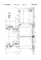
- FIG. 2 is a side-elevational view of a section through the open-end spinning machine at a spinning station, with a transport vehicle for sliver cans that is positioned in front of the spinning stations;
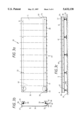
- FIG. 3a is a partly broken-away plan view of silver can parking places, forming a self-contained structural unit
- FIG. 3b is a cross-sectional view through the structural unit
- FIG. 3c is a front-elevational view of the structural unit.
- FIG. 4 is a partly broken-away plan view of a sliver transport system according to the invention.
- reference numeral 1 diagrammatically illustrates an open-end spinning machine, as an example of a sliver-processing textile machine.
- the machine includes a number of spinning stations 2, located side by side. In each of these spinning stations, yarn 3 is spun and wound up onto cross-wound bobbins or cheeses 4.
- the yarn is spun in a known manner from sliver 5 and is drawn by a so-called condenser 8 from sliver cans 6 into a so-called spinning box 7, where the yarn formation takes place.
- the finished yarn 3 leaves the spinning box 7 through a draw-off tubule 9.
- One can 6 is assigned to each spinning station 2.
- the cans stand side by side below the spinning stations.
- the cans have an elongated rectangular shape, so that the cans can easily be disposed beneath the spinning stations.
- Each can is approximately as wide as one spinning station.
- a can transport vehicle 10 is positioned in front of the spinning machine 1.
- the can transport vehicle 10 is just exchanging an empty sliver can for a filled one at a spinning station.
- the transport vehicle 10 includes a chassis 11 with steerable and driven wheels 12.
- the transport vehicle has a rectangular outline and on one short side on its vehicle frame it carries a drive device 13, with a non-illustrated motor that in this case drives the wheels 12, and a control device 14 that processes control commands and controls can changes.
- the can transport vehicle 10 is guided along the spinning machine 1 through the use of an induction loop 15 and from there it is guided to an empty, non-illustrated can discharge station, to a can delivery station for filled sliver cans, optionally to further non-illustrated spinning machines and to a so-called can buffer, which can temporarily store filled sliver cans, for instance. Temporary storage of empty cans can also be provided for in a can buffer.
- the motion along the induction loop 15 can be in both directions of travel, as is symbolically represented by a double arrow 16.
- the transmission of control commands can also be carried out through radio signals.
- the positioning in front of the various work stations can be carried out, for instance, through the use of devices that are known from German Utility Model DE-GM 88 12 622.
- the can transport vehicle 10 has seven parking places 17a-17g for rectangular cans.
- rectangular cans 18a-18g stand broad side to broad side one after the other.
- the sliver can 18e is just being thrust below a spinning station in FIG. 1.
- the cans 18f and 18g on the parking places 17f and 17g are empty cans, which have already been replaced by full cans at spinning stations.
- the cans 6 at the textile machine 1 are raised somewhat above a normal floor 19 on the can stands according to the invention, which form a self-contained structural unit 20 of can parking places.
- the can stand according to the invention makes it easier for the can transport vehicle 10 to change the sliver cans, since all of the cans are located at the same level.
- One can changer 21a-21g is provided for each of the parking places 17a-17g on the can transport vehicle 10.
- the can changer may be constructed in accordance with FIGS. 2-4 of German Published, Non-Prosecuted Application DE 43 23 726 A1, corresponding to U.S. application Ser. No. 08/276,168, filed Jul. 15, 1994, now U.S. Pat. No. 5,511,372.
- the cans can be manipulated through the use of an actuatable magnet 22, which enters into operative connection with a magnetizable metal plate 23 mounted on end surfaces of the cans.
- the sliver cans have clamps 24 on their end surfaces, which are oriented toward the associated workstation.
- a beginning end 25 of the sliver is firmly fixed in the sliver clamp 24 at a defined length.
- a manipulator it is possible by using a manipulator to introduce the beginning 25 of the sliver into the spinning station. This can be carried out, for instance, by using a yarn inserter 26, which is disposed on a servicing device 27 that patrols along the work stations of the spinning machine and carries out a piecing operation, for instance after a yarn break or after a change of sliver cans.
- the sliver In order to enable the carrying out of a piecing operation if a sliver can has been changed, the sliver must first be placed from the new can into the spinning station. This is performed fully automatically, through the use of a manipulator which is known, for instance, from German Published, Non-Prosecuted Application DE 42 04 044 A1, corresponding to U.S. Pat. No. 5,293,739.
- a manipulator which is known, for instance, from German Published, Non-Prosecuted Application DE 42 04 044 A1, corresponding to U.S. Pat. No. 5,293,739.
- the sliver clamps In order to assure that such a device for automatically delivering the sliver will always find the sliver at the same location, the sliver clamps must all be aligned in the same three-dimensional position. Such an alignment is advantageously possible with the parking places that are combined according to the invention into a structural unit, since they are vertically adjustable and thus can be aligned with respect
- FIG. 2 shows a side view of a section through the open-end spinning machine.
- the section is taken at a boundary between two spinning stations which are located next to one another.
- the spinning machine is a double-sided spinning machine, so that pairs of work stations abut one another at their backs.
- the parking places for the cans are disposed in such a way that the cans each abut at their backs when they are disposed below the spinning stations.
- a servicing device 27' and a sliver inserter 26' connected to it are shown in phantom by dot-dashed lines indicating their outlines.
- these devices can additionally be provided in such a way that the spinning stations can be serviced simultaneously on both sides.
- a can stand K with parking places S can be seen in cross section below the sliver cans 6.
- the various structural units 20 of the various sections abut one another with their backs below the spinning stations and are screwed together there. They are fitted between fixed locations of machine parts, namely supports 28 and 29 of the respective sections.
- FIG. 3a shows a plan view on a can stand K, which forms a self-contained structural unit 20 of parking places S.
- the structural unit includes a sheet-metal panel 30, which is bent in a U on each of its long sides. Short legs 31 and 32 of the U profile are oriented toward the floor 19, as is shown in FIG. 2.
- Vertically adjustable floor supports 33 are disposed at regular, fixed intervals in the short legs 31 and 32 of the various U profiles, to enable vertically aligning the sheet-metal panels 30. With the aid of the vertically adjustable floor support 33, it is possible to compensate for unevenness of the floor 19, as can be seen from FIG. 3c. While in FIG.
- a dot-dash line 190 indicates an ideal profile for the floor
- the solid line 19 indicates the actual profile of the floor.
- the side of the structural unit facing toward the can transport vehicle 10 has an incline 34.
- the incline facilitates the transfer of cans from the can transport vehicle to the parking places as well as the takeover of cans onto the can transport vehicle.
- any unevenness in the floor of the kind which is visible in FIG. 3c and having an effect on the position of the can transport vehicle, is attenuated. If the can transport vehicle is standing in such a way that its parking places 17a-17g are located at a lower level than the surfaces of the can parking places, then the cans to be transferred can be raised to the parking places S through the incline 34.
- the parking places S of the structural unit 20 cannot be any higher than the parking places 17a-17g of the can transport vehicle 10 than the distance made possible by the compensation of the level difference performed by the incline 34 dictated by a height difference 35.
- the cross section through the structural unit 20 of parking places S shows that there is a stop 37 on a rear bottom leg 36 of the U-shaped profile, so that when the cans are slipped on they cannot be pushed beyond the rear edge.
- the structural units 20 associated with the various sections are screwed together by their backs 36, below the abutting spinning stations 2.
- dot-dashed lines demarcate the parking places S of the cans. Points are also shown where the vertically adjustable bottom supports 33 can be screwed in. Recesses 39 are provided on right-hand and left-hand short sides of the structural group 20, so that the structural group can be inserted between the supports 28 and 29 of the respective sections on the machines. If the structural units are each to be set up by themselves as can buffers outside a machine, then at those locations the screw fastenings can be made to intervening supports, so that the cans, particularly those set up in the peripheral regions, will not fall out at the side.
- the surface of the sheet-metal panel 30 encompassing the parking places S of the can stand K of the structural unit 20 is flat. It is also possible, however, as in German Utility Model DE-GM 88 12 622, to provide ribs that serve to guide the cans. Such ribs can be advantageous, and can be mounted in accordance with the dot-dash lines on the surface of the sheet-metal panel 30, whenever the cans are narrower than the parking places. If each of the cans are just as wide as the parking places, then the possibility exists of self-alignment of the cans in accordance with the boundary of the parking places that are provided.
- the lateral guides of the cans can also be disposed adjustably or can be constructed as beads impressed into the sheet-metal panel 30. However, if the sheet-metal panel were profiled to provide lateral guidance to the cans, then the fixation to a certain can width would be effected in this way.
- a marking or a sensor 41 can be provided on an end surface 38 of the structural unit at each parking place S, as can be seen from the front view of the structural unit 20 in FIG. 3c.
- this marking can be an addressable memory chip, in which the data of the can deposited on this parking place can be written by the can transport vehicle.
- a device for bidirectional communication at each can parking place so that the can transport vehicle setting down or picking up a can is able to communicate at the particular parking place with a transceiver that is installed there, which receives all of the information pertaining to the can and upon a search for a certain can outputs this information again to the can transport vehicle that is looking for it.
- An information carrier can also be provided on the can itself. The coding of the can is able to take various forms. The can transport vehicle in this case comes into operative connection with each of the cans in order to identify them. Then no markings or sensors are necessary at the parking place of the particular can.
- each removal of a can and each can change can be carried out by the can transport vehicle through the use of a bidirectional data exchange with a read/write device at a can parking place.
- the structural groups provided as can buffers will be equipped in the same way in such a case as a machine and will thus be detected by the can transport vehicle as a pseudo machine.
- the can transport vehicle will recognize whether a pseudo machine, or in other words a can stand K acting as a can buffer, is present, or an actual textile machine 1, from the fact that the can stands K are each assigned a position identification PE that can be detected by a positioning device PM.
- a sliver can transport system according to the invention will be described below in conjunction with FIG. 4.
- the can transport vehicle 10 is located at a can delivery station KLS in order to fill its empty parking places with filled sliver cans 50. While the parking place 17a remains free to receive an empty can the first time that a can change takes place, the parking places 17b-17g are loaded with the filled cans 50, as is indicated by arrows 51.
- the filled sliver cans 50 are brought on a transport device 52 from a non-illustrated path where the cans are filled, as is indicated by an arrow 53. They are set down onto the can stand K at the can delivery station KLS by the transport device 52. This can stand K includes 12 parking places S for sliver cans.
- the number of parking places S on a can stand K corresponds to the number of parking places in a section SE of one of three sliver-processing textile machines T1-T3 shown in FIG. 4.
- Each of the textile machines T1-T3 includes at least two sections SE of workstations, and each section includes the same number of workstations.
- Each section SE is assigned one can stand K, having parking places S which are each assigned to the work stations located above them.
- the can transport vehicle 10 is carried from the can delivery station KLS to the various textile machines T1-T3 through the use of the induction loop 15.
- a can buffer KPV for full cans is provided next to the textile machines and is reachable directly from the can delivery station KLS.
- a can buffer KPL for empty cans is located before a discharge station ASL for empty cans.
- Both the full-can buffer KPV and the empty-can buffer KPL include two can stands K in the present exemplary embodiment, which are screwed to one another at their backs. Each can stand offers the same number of parking places S as a section SE has in each of the textile machines T1-T3.
- a first can stand K of the can buffer KPV for full cans is already occupied with sliver-filled cans 50, while a second can stand K still has parking places S that are entirely empty.
- the empty-can buffer KPL in the present example likewise includes two can stands K, which are again screwed together at the back and are enclosed by the closed loop 15 for the travel path of the can transporter 10.
- the can stands K each have as many parking places as one of the sections SE of one of the textile machines T1-T3.
- One can stand K is already entirely filled with empty cans 54.
- the parking places S of the other can stand K are not yet occupied.
- the full-can buffer KPV offers the opportunity, for example in the case of overproduction or at batch changing times and upon cancellation of orders, to temporarily store the full cans 50 that are output by the can delivery station KLS for a certain period of time.
- the empty-can buffer KPL in the event of disruptions along the path or for other reasons, can store unneeded empty cans 54 temporarily for a certain period.
- the discharge station for empty cans in this case again includes a can stand K with a number of parking places S for empty cans 54 that matches the number of parking places at one section SE of one of the textile machines T1-T3.
- the empty cans are transported on a transport device 55 to the filling station along the non-illustrated path, as is indicated by an arrow 56.
- the can stands K each have the position identifier PE that is detectable by the positioning device PM of the can vehicle 10.
- These position identifiers PE are suitably disposed at the beginning of a can stand K, in terms of the direction of arrival of the can transport vehicle 10.
- the can transport vehicle 10 can position itself at each can stand K for an intended can change.
- path locations BP which, for instance, are disposed in the induction loops 15, and relative to which the can stands K can be aligned.
Landscapes
- Engineering & Computer Science (AREA)
- Mechanical Engineering (AREA)
- Textile Engineering (AREA)
- Spinning Or Twisting Of Yarns (AREA)
- Preliminary Treatment Of Fibers (AREA)
Applications Claiming Priority (2)
| Application Number | Priority Date | Filing Date | Title |
|---|---|---|---|
| DE4429254A DE4429254C2 (de) | 1994-08-18 | 1994-08-18 | Faserbandkannentransportersystem |
| DE4429254.6 | 1994-08-18 |
Publications (1)
| Publication Number | Publication Date |
|---|---|
| US5632138A true US5632138A (en) | 1997-05-27 |
Family
ID=6525958
Family Applications (1)
| Application Number | Title | Priority Date | Filing Date |
|---|---|---|---|
| US08/517,422 Expired - Fee Related US5632138A (en) | 1994-08-18 | 1995-08-18 | Stand for receiving sliver cans |
Country Status (4)
| Country | Link |
|---|---|
| US (1) | US5632138A (de) |
| CH (1) | CH690780A5 (de) |
| DE (1) | DE4429254C2 (de) |
| IT (1) | IT1277378B1 (de) |
Cited By (10)
| Publication number | Priority date | Publication date | Assignee | Title |
|---|---|---|---|---|
| US5992136A (en) * | 1996-08-16 | 1999-11-30 | Langen; Manfred | Method for exchanging sliver cans at a spinning machine |
| US6161257A (en) * | 1998-04-30 | 2000-12-19 | Rieter Ingolstadt Spinnereimaschinenbau Ag | Process for can delivery and removal at a textile machine |
| EP1098017A3 (de) * | 1999-11-05 | 2001-07-04 | Manfred Langen | Spinnkannentransporter |
| US6256973B1 (en) * | 1997-04-04 | 2001-07-10 | Manfred Langen | Transporting and storage system for spinning cans |
| US6363702B2 (en) * | 2000-04-12 | 2002-04-02 | Evelyn Langen | Transportation and storage system for rectangular spinning cans |
| WO2004099052A1 (de) * | 2003-05-08 | 2004-11-18 | Maschinenfabrik Rieter Ag | Verfahren zur faserbandbehandlung in der kämmerei, kannengestell für kämmereimaschinen sowie maschinen in der kämmerei |
| US20150220146A1 (en) * | 2014-01-31 | 2015-08-06 | Wells Lamont Industry Group Llc | Cut resistant glove for use with capacitive sensing devices |
| US11478028B2 (en) | 2019-04-05 | 2022-10-25 | Wells Lamont Industry Group Llc | Disposable cut-resistant glove |
| US20230416952A1 (en) * | 2020-11-24 | 2023-12-28 | Maschinenfabrik Rieter Ag | Method for carrying out an automatic can changing process at a spinning station of a spinning machine, and spinning machine and movable can changer |
| US20230416951A1 (en) * | 2020-11-24 | 2023-12-28 | Maschinenfabrik Rieter Ag | Method for carrying out an automatic can changing process at a spinning station of a spinning machine, and spinning machine and movable can changer |
Families Citing this family (1)
| Publication number | Priority date | Publication date | Assignee | Title |
|---|---|---|---|---|
| DE19654375A1 (de) * | 1996-12-24 | 1997-06-05 | Hans W Schwalm | Verfahren und Einrichtungen zum Wechsel von Spinnkannen an Spinnmaschinen |
Citations (16)
| Publication number | Priority date | Publication date | Assignee | Title |
|---|---|---|---|---|
| US2690641A (en) * | 1949-10-29 | 1954-10-05 | Schiess Ag | Sectional spinning machine |
| US3134144A (en) * | 1960-12-30 | 1964-05-26 | Greenwood Mills Inc | Carding and drafting apparatus |
| US3816991A (en) * | 1973-05-07 | 1974-06-18 | Toyoda Automatic Loom Works | Method and device for supplying sliver to a spinner machine |
| US4012893A (en) * | 1974-12-24 | 1977-03-22 | Rieter Machine Works, Ltd. | Method of loading transporting trolleys with full cans or the like and supplying full cans to spinning machines fed with fiber sliver and apparatus for implementing the method |
| US4179773A (en) * | 1978-04-27 | 1979-12-25 | Platt Saco Lowell Limited | Means for severing and compacting coiled sliver |
| DE3621370A1 (de) * | 1985-09-10 | 1987-03-19 | Truetzschler & Co | Vorrichtung zum transport mindestens einer kanne zwischen einer faserbandabliefernden und einer faserbandgespeisten spinnereimaschine |
| US4843810A (en) * | 1986-12-04 | 1989-07-04 | Zinser Textilmaschinen Gmbh | Apparatus for inclination adjustment of a traveling service unit for a textile spinning mill machine |
| DE8812622U1 (de) * | 1988-10-07 | 1990-02-08 | W. Schlafhorst & Co, 4050 Mönchengladbach | Vorrichtung zum Auswechseln der Faserbandkannen einer Spinnmaschine |
| DE4018088A1 (de) * | 1989-06-19 | 1991-01-10 | Elitex Zavody Textilniho | Verfahren und vorrichtung zur automatisierung des garnherstellungsvorgangs, besonders in spinnereien mit rotorspinnmaschinen |
| US5138828A (en) * | 1989-08-30 | 1992-08-18 | Hans Stahlecker | Spinning facility having at least one exchanging cart for the exchange of cans |
| DE4231697A1 (de) * | 1991-09-23 | 1993-04-01 | Elitex Usti Nad Orlici | Faserbandbehaelter |
| US5222856A (en) * | 1990-06-05 | 1993-06-29 | Murata Kikai Kabushiki Kaisha | Can conveying system |
| US5293739A (en) * | 1991-08-01 | 1994-03-15 | W. Schlafhorst Ag & Co. | Method and apparatus for supplying a sliver to a spinning position of a spinning machine |
| DE4323726A1 (de) * | 1993-07-15 | 1995-01-19 | Schlafhorst & Co W | Transportfahrzeug für Faserbandkannen |
| US5386684A (en) * | 1988-12-09 | 1995-02-07 | W. Schlafhorst & Co. | Data exchange coordinating apparatus for a textile machine |
| US5390484A (en) * | 1991-07-31 | 1995-02-21 | W. Schlafhorst Ag & Co. | Sliver can transport carriage and method for automatic sliver can exchange operations |
-
1994
- 1994-08-18 DE DE4429254A patent/DE4429254C2/de not_active Expired - Fee Related
-
1995
- 1995-06-28 CH CH01895/95A patent/CH690780A5/de not_active IP Right Cessation
- 1995-07-28 IT IT95MI001655A patent/IT1277378B1/it active IP Right Grant
- 1995-08-18 US US08/517,422 patent/US5632138A/en not_active Expired - Fee Related
Patent Citations (17)
| Publication number | Priority date | Publication date | Assignee | Title |
|---|---|---|---|---|
| US2690641A (en) * | 1949-10-29 | 1954-10-05 | Schiess Ag | Sectional spinning machine |
| US3134144A (en) * | 1960-12-30 | 1964-05-26 | Greenwood Mills Inc | Carding and drafting apparatus |
| US3816991A (en) * | 1973-05-07 | 1974-06-18 | Toyoda Automatic Loom Works | Method and device for supplying sliver to a spinner machine |
| US4012893A (en) * | 1974-12-24 | 1977-03-22 | Rieter Machine Works, Ltd. | Method of loading transporting trolleys with full cans or the like and supplying full cans to spinning machines fed with fiber sliver and apparatus for implementing the method |
| US4179773A (en) * | 1978-04-27 | 1979-12-25 | Platt Saco Lowell Limited | Means for severing and compacting coiled sliver |
| DE3621370A1 (de) * | 1985-09-10 | 1987-03-19 | Truetzschler & Co | Vorrichtung zum transport mindestens einer kanne zwischen einer faserbandabliefernden und einer faserbandgespeisten spinnereimaschine |
| US4843810A (en) * | 1986-12-04 | 1989-07-04 | Zinser Textilmaschinen Gmbh | Apparatus for inclination adjustment of a traveling service unit for a textile spinning mill machine |
| DE8812622U1 (de) * | 1988-10-07 | 1990-02-08 | W. Schlafhorst & Co, 4050 Mönchengladbach | Vorrichtung zum Auswechseln der Faserbandkannen einer Spinnmaschine |
| US5386684A (en) * | 1988-12-09 | 1995-02-07 | W. Schlafhorst & Co. | Data exchange coordinating apparatus for a textile machine |
| DE4018088A1 (de) * | 1989-06-19 | 1991-01-10 | Elitex Zavody Textilniho | Verfahren und vorrichtung zur automatisierung des garnherstellungsvorgangs, besonders in spinnereien mit rotorspinnmaschinen |
| US5138828A (en) * | 1989-08-30 | 1992-08-18 | Hans Stahlecker | Spinning facility having at least one exchanging cart for the exchange of cans |
| US5222856A (en) * | 1990-06-05 | 1993-06-29 | Murata Kikai Kabushiki Kaisha | Can conveying system |
| US5390484A (en) * | 1991-07-31 | 1995-02-21 | W. Schlafhorst Ag & Co. | Sliver can transport carriage and method for automatic sliver can exchange operations |
| US5293739A (en) * | 1991-08-01 | 1994-03-15 | W. Schlafhorst Ag & Co. | Method and apparatus for supplying a sliver to a spinning position of a spinning machine |
| DE4231697A1 (de) * | 1991-09-23 | 1993-04-01 | Elitex Usti Nad Orlici | Faserbandbehaelter |
| DE4323726A1 (de) * | 1993-07-15 | 1995-01-19 | Schlafhorst & Co W | Transportfahrzeug für Faserbandkannen |
| US5511372A (en) * | 1993-07-15 | 1996-04-30 | W. Schlafhorst Ag & Co | Transport vehicle for sliver cans |
Cited By (12)
| Publication number | Priority date | Publication date | Assignee | Title |
|---|---|---|---|---|
| US5992136A (en) * | 1996-08-16 | 1999-11-30 | Langen; Manfred | Method for exchanging sliver cans at a spinning machine |
| US6256973B1 (en) * | 1997-04-04 | 2001-07-10 | Manfred Langen | Transporting and storage system for spinning cans |
| US6161257A (en) * | 1998-04-30 | 2000-12-19 | Rieter Ingolstadt Spinnereimaschinenbau Ag | Process for can delivery and removal at a textile machine |
| US6336258B2 (en) * | 1998-04-30 | 2002-01-08 | Rieter Ingolstadt Spinnereimaschinebau Ag | Process for can delivery and removal at a textile machine |
| EP1098017A3 (de) * | 1999-11-05 | 2001-07-04 | Manfred Langen | Spinnkannentransporter |
| US6363702B2 (en) * | 2000-04-12 | 2002-04-02 | Evelyn Langen | Transportation and storage system for rectangular spinning cans |
| WO2004099052A1 (de) * | 2003-05-08 | 2004-11-18 | Maschinenfabrik Rieter Ag | Verfahren zur faserbandbehandlung in der kämmerei, kannengestell für kämmereimaschinen sowie maschinen in der kämmerei |
| US20150220146A1 (en) * | 2014-01-31 | 2015-08-06 | Wells Lamont Industry Group Llc | Cut resistant glove for use with capacitive sensing devices |
| US10168774B2 (en) * | 2014-01-31 | 2019-01-01 | Wells Lamont Industry Group Llc | Cut resistant glove for use with capacitive sensing devices |
| US11478028B2 (en) | 2019-04-05 | 2022-10-25 | Wells Lamont Industry Group Llc | Disposable cut-resistant glove |
| US20230416952A1 (en) * | 2020-11-24 | 2023-12-28 | Maschinenfabrik Rieter Ag | Method for carrying out an automatic can changing process at a spinning station of a spinning machine, and spinning machine and movable can changer |
| US20230416951A1 (en) * | 2020-11-24 | 2023-12-28 | Maschinenfabrik Rieter Ag | Method for carrying out an automatic can changing process at a spinning station of a spinning machine, and spinning machine and movable can changer |
Also Published As
| Publication number | Publication date |
|---|---|
| ITMI951655A0 (it) | 1995-07-28 |
| DE4429254A1 (de) | 1996-02-22 |
| ITMI951655A1 (it) | 1997-01-28 |
| IT1277378B1 (it) | 1997-11-10 |
| CH690780A5 (de) | 2001-01-15 |
| DE4429254C2 (de) | 2003-12-24 |
Similar Documents
| Publication | Publication Date | Title |
|---|---|---|
| US5632138A (en) | Stand for receiving sliver cans | |
| US4979360A (en) | Transport and handling system for multi-position textile machines | |
| US4694539A (en) | Method and device for exchanging empty cans with cans filled with sliver | |
| DE3627586C2 (de) | ||
| US5022807A (en) | Depository for accumulations of paper sheets | |
| US4697310A (en) | Device for exchanging empty cans with cans filled with sliver | |
| JPS62501066A (ja) | 精紡機の紡ぎ位置へ満載のケンスを自動的に搬入しかつ該紡ぎ位置から空のケンスを搬出するための装置と方法 | |
| JPH11116006A (ja) | 自動倉庫システム | |
| JP2845980B2 (ja) | 自動紡績機の紡糸部にスライバを供給する方法と装置 | |
| US6056228A (en) | Tube magazine for a cheese producing textile machine | |
| US5582354A (en) | Cheese-producing textile machine | |
| EP0478164A1 (de) | Spulentransportvorrichtung | |
| US4972669A (en) | Automatic spinning machine with silver can replacing apparatus | |
| JP3031092B2 (ja) | 給糸交換方法 | |
| JPH038670A (ja) | 各1つのまたは複数個の紡糸機と巻き取り機との間の結合装置機構部の内部における情報装置 | |
| US5720161A (en) | Sliver can, can changer and pallet | |
| EP0796812A1 (de) | Verfahren und Vorrichtung zum gleichzeitigen Wickeln einer Mehrzahl von Garnpartien | |
| JPS6297926A (ja) | 精紡機、特にリング精紡機のボビンクリ−ルにおける引渡し位置において粗糸空ボビンを粗糸フルボビンと交換するための方法および装置 | |
| CN117947550B (zh) | 用于纺纱条筒的坡道装置及纺纱机器 | |
| US5451005A (en) | Bobbin evacuation on a movable conveyor belt | |
| US5414986A (en) | Method and apparatus for supplying sliver to the spinning stations of spinning machines in the form of a transport-containerless bunch | |
| US5628173A (en) | Method and apparatus for feeding sliver to a spinning machine without sliver cans at spinning stations | |
| JPH11116005A (ja) | 自動倉庫システム | |
| US6012671A (en) | Tube feeding device for cheese-producing textile machines | |
| JP2956780B2 (ja) | 紡績機とワインダとの複合設備 |
Legal Events
| Date | Code | Title | Description |
|---|---|---|---|
| AS | Assignment |
Owner name: W. SCHLAFHORST AG & CO., GERMANY Free format text: ASSIGNMENT OF ASSIGNORS INTEREST;ASSIGNOR:LIEDGENS, HANS-PETER;REEL/FRAME:008288/0947 Effective date: 19950907 |
|
| FEPP | Fee payment procedure |
Free format text: PAYOR NUMBER ASSIGNED (ORIGINAL EVENT CODE: ASPN); ENTITY STATUS OF PATENT OWNER: LARGE ENTITY |
|
| FPAY | Fee payment |
Year of fee payment: 4 |
|
| FPAY | Fee payment |
Year of fee payment: 8 |
|
| REMI | Maintenance fee reminder mailed | ||
| LAPS | Lapse for failure to pay maintenance fees | ||
| LAPS | Lapse for failure to pay maintenance fees |
Free format text: PATENT EXPIRED FOR FAILURE TO PAY MAINTENANCE FEES (ORIGINAL EVENT CODE: EXP.); ENTITY STATUS OF PATENT OWNER: LARGE ENTITY |
|
| STCH | Information on status: patent discontinuation |
Free format text: PATENT EXPIRED DUE TO NONPAYMENT OF MAINTENANCE FEES UNDER 37 CFR 1.362 |
|
| FP | Lapsed due to failure to pay maintenance fee |
Effective date: 20090527 |