US5647775A - Electrical connector with terminal locking means - Google Patents
Electrical connector with terminal locking means Download PDFInfo
- Publication number
- US5647775A US5647775A US08/568,917 US56891795A US5647775A US 5647775 A US5647775 A US 5647775A US 56891795 A US56891795 A US 56891795A US 5647775 A US5647775 A US 5647775A
- Authority
- US
- United States
- Prior art keywords
- terminal
- electrical connector
- housing
- locking member
- wall
- Prior art date
- Legal status (The legal status is an assumption and is not a legal conclusion. Google has not performed a legal analysis and makes no representation as to the accuracy of the status listed.)
- Expired - Lifetime
Links
- 238000003780 insertion Methods 0.000 claims abstract description 5
- 230000037431 insertion Effects 0.000 claims abstract description 5
- 230000013011 mating Effects 0.000 claims description 6
- 239000003989 dielectric material Substances 0.000 claims description 5
- 239000007769 metal material Substances 0.000 claims description 4
- 238000004519 manufacturing process Methods 0.000 description 5
- 239000004020 conductor Substances 0.000 description 2
- 238000000034 method Methods 0.000 description 2
- 238000002788 crimping Methods 0.000 description 1
- 239000011810 insulating material Substances 0.000 description 1
- 238000000465 moulding Methods 0.000 description 1
- 230000000717 retained effect Effects 0.000 description 1
Images


Classifications
-
- H—ELECTRICITY
- H01—ELECTRIC ELEMENTS
- H01R—ELECTRICALLY-CONDUCTIVE CONNECTIONS; STRUCTURAL ASSOCIATIONS OF A PLURALITY OF MUTUALLY-INSULATED ELECTRICAL CONNECTING ELEMENTS; COUPLING DEVICES; CURRENT COLLECTORS
- H01R13/00—Details of coupling devices of the kinds covered by groups H01R12/70 or H01R24/00 - H01R33/00
- H01R13/40—Securing contact members in or to a base or case; Insulating of contact members
- H01R13/42—Securing in a demountable manner
- H01R13/436—Securing a plurality of contact members by one locking piece or operation
- H01R13/4361—Insertion of locking piece perpendicular to direction of contact insertion
-
- H—ELECTRICITY
- H01—ELECTRIC ELEMENTS
- H01R—ELECTRICALLY-CONDUCTIVE CONNECTIONS; STRUCTURAL ASSOCIATIONS OF A PLURALITY OF MUTUALLY-INSULATED ELECTRICAL CONNECTING ELEMENTS; COUPLING DEVICES; CURRENT COLLECTORS
- H01R13/00—Details of coupling devices of the kinds covered by groups H01R12/70 or H01R24/00 - H01R33/00
- H01R13/46—Bases; Cases
- H01R13/50—Bases; Cases formed as an integral body
- H01R13/501—Bases; Cases formed as an integral body comprising an integral hinge or a frangible part
Definitions
- This invention generally relates to the art of electrical connectors and, particularly, to an electrical connector which incorporates a locking member for locking a terminal in a connector housing.
- Typical electrical connectors include housings normally of insulating material and having a plurality of cavities or passages into which male or female terminals are inserted.
- each terminal normally is precrimped to a wire conductor and then inserted into a housing cavity where it is retained in place by a locking structure.
- the locking structure may include resilient tangs or latch projections which engage shoulders on the housing within the cavity. Mating plug and socket housings then can be joined in order to interconnect mating male and female terminals mounted in the housings, or the housings might be joined with other terminal supporting devices.
- a terminal may not be fully inserted into its housing cavity during assembly whereby the locking structure is not effective to secure the terminal in place.
- the incompletely mounted terminal can be pushed out of position so that the interconnection between terminals is not made.
- a terminal can subsequently work loose because of vibrations or other extraneous forces and cause a faulty or intermittent connection. Consequently, a variety of systems have been designed wherein a separate terminal locking member is employed on the connector housing to act as either a primary or a secondary locking means. These locking members are inserted longitudinally or laterally into the connector housing. Those locking members inserted longitudinally, although working satisfactorily for certain applications, require two separate parts to be molded, inventoried and shipped which adds to the cost and labor of the connector.
- An object, therefore, of the invention is to provide a new and improved electrical connector of the character described, incorporating a novel terminal locking system.
- the electrical connector includes a dielectric housing having a forward mating end, a rearward terminating end, an elongated terminal-receiving cavity extending in an axial direction between the ends, and a window in an outer side wall of the housing communicating with the cavity.
- An elongated terminal is insertable in the axial direction into a final position.
- the terminal includes a forward contact end, a rearward conductor-engaging end and an intermediate body portion between the ends.
- the body portion has a wall transverse to the axial direction and alignable with the window when the terminal is in its final position.
- a terminal locking member has a two-pronged locking projection adapted to pass through the window into the cavity with the prongs engaging opposite sides of the transverse wall of the terminal. This prevents axial movement of the terminal relative to the cavity.
- the terminal is stamped and formed of sheet metal material.
- the terminal includes spaced side walls with the transverse wall being formed from portions of each side wall bent inwardly toward each other.
- the housing is molded of plastic dielectric material with an integral living hinge portion connecting the terminal locking member integrally with the housing.
- At least one prong of the two-pronged locking projection includes a camming surface for engaging the transverse wall of the terminal and moving the terminal from at least one position of incomplete insertion to the final position of the terminal.
- each prong of the two-pronged locking projection includes a camming surface for engaging the transverse wall of the terminal to guide the wall between the prongs.
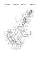
- FIG. 1 is a perspective view of a first embodiment of an electrical connector incorporating the concepts of the invention
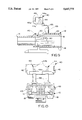
- FIG. 2 is a vertical section taken generally along line 2--2 of FIG. 3;
- FIG. 3 is a top plan view of the housing in the open position of the terminal locking member as shown in FIG. 1;
- FIG. 4 is a rear elevational view similar looking toward the right-hand end of FIG. 3;
- FIG. 5 is a view similar to that of FIG. 2, but with a terminal in its final position and the terminal locking member in its closed position;
- FIG. 6 is a fragmented horizontal section taken generally along line 6--6 of FIG. 5;
- FIG. 7 is a view similar to that of FIG. 2, but of a second embodiment of the invention.
- FIG. 8 is a view similar to that of FIG. 4, but of the embodiment shown in FIG. 7;
- FIG. 9 is a view similar to that of FIGS. 2 and 7, but of a third embodiment of the invention.
- FIG. 10 is a view similar to that of FIG. 8, but of the third embodiment of the invention corresponding to the FIG. 9.
- an electrical connector generally designated 10 which includes a dielectric housing, generally designated 12.
- the housing is unitarily molded of dielectric material such as plastic or the like.
- the housing has a forward mating end 14 and a rearward terminating end 16.
- a plurality of elongated terminal-receiving cavities 18 extend in an axial direction between the ends.
- a window 20 in an outer wall 22 of the housing communicates with each cavity 18.
- An elongated terminal is insertable into each cavity 18 in housing 12 in an axial direction as indicated by arrow "A" (FIG. 1). Only one terminal is shown in FIG. 1, but each terminal includes a forward contact end 26, a rearward conductor-engaging end 28 and an intermediate body portion 30 between the ends.
- the conductor-engaging end has two pairs of crimp arms 32 for crimping onto a conductor 34, such as an insulated stranded wire.
- Body portion 30 has a wall, generally designated 36, transverse to axial direction "A" and alignable with the window 20 of the respective cavity 18 when the terminal is in its final inserted position described hereinafter.
- the terminal is stamped and formed of sheet metal material, and body portion 30 includes a pair of transversely spaced side walls 38. Transverse wall 36 is formed from portions 36a of each side wall 38 bent inwardly toward each other.
- a terminal locking member is hinged to housing 12 by an integral living hinge portion 42 as best seen in FIG. 2, whereby the locking member is molded integrally with the housing. Therefore, the locking member is pivotable about living hinge 42 in the direction of arrow "B" from an open or inoperative position shown in FIGS. 2-4 to a closed locking position described hereinafter.
- Terminal locking member 40 has a two-pronged locking projection 44 adapted to pass through each window 20 in outer side wall 22 of the housing and into the respective cavity 18.
- Each projection includes two prongs 44a and 44b adapted to embrace transverse wall 36 of the respective terminal 24, as will be seen hereinafter.
- the terminal locking member includes a pair of U-shaped latch arms 46 at opposite sides of the locking member to define a pair of latch shoulders 46a which latchingly engage a pair of chamfered latch bosses 48 on opposite sides of housing 12.
- connector 10 is assembled by inserting one of the terminals 24 into each terminal-receiving cavity 18 in housing 12 in the axial direction "A". In its final or fully inserted position as shown, a pair of forwardly facing abutment shoulders 50 on side walls 38 of the terminal abuts an interior shoulder 52 within the respective cavity of the housing.
- terminal locking member 40 (FIG. 5) is pivoted about living hinge 42 to its closed locking position shown in FIG. 5.
- prongs 44a and 44b of two-pronged locking projection 44 engage on opposite sides of transverse wall 36 as clearly seen in FIGS. 5 and 6.
- a lip 54 thereof engages the top of outer wall 22 of housing 12 rearwardly of windows 20.
- the locking member is held in its closed locking position by latch arms 46 engaging latch bosses 48 on the housing.
- prong 44a of two-pronged projection 44 includes an inwardly facing camming surface 56a
- prong 44b includes an inwardly facing camming surface 56b.
- the camming surfaces are effective to engage transverse wall 36 of the terminal to guide the wall between prongs 44a and 44b.
- camming surface 56a on prong 44a is effective to drive the terminal forwardly to abut shoulders 50 and 52 in response to closing the terminal locking member. It can be seen that camming surface 56b on prong 44b is more drastic than camming surface 56a on prong 44a. This is to provide increased clearance between prong 44b and transverse wall 36 of the terminal as locking member 40 pivots about living hinge 42.
- terminal locking member 40 can act as either a primary or a secondary locking means.
- the terminal locking member is used as a secondary locking means. More particularly, referring to FIGS. 5 and 6, housing 12 has a pair of flexible cantilevered locking arms 60 (see FIG. 6) which are effective to lock behind a pair of rearwardly facing shoulders 62 (FIGS. 1 and 5) formed from side walls 38 of body portion 30 of the terminal. In this system, terminal locking member 40 would be used as a secondary locking means.
- FIGS. 7-10 show two alternate embodiments of the invention wherein like numerals have been applied to designate like elements or components described above in relation to FIGS. 1-6.
- the difference in the embodiments of FIGS. 7-10 versus the embodiment of FIGS. 1-6 resides in the means for integrally connecting terminal locking member 40 to connector housing 12.
- the terminal locking member is integrally molded with the housing by means of a living hinge portion 42 as best seen in FIGS. 2 and 5.
- terminal locking member 40 is integrally molded with connector housing 12 by means of elongated tether straps 66 in FIGS. 7 and 8 and tether straps 68 in FIGS. 9 and 10.
- tether straps 66 and 68 allow the terminal locking member to be moved from an open inoperative position shown in full lines in FIGS. 7-10 to a closed locking position shown in phantom in FIGS. 7 and 9. Otherwise, the terminal locking member functions the same as described above in relation to the embodiment of connector 10 in FIGS. 1-6.
- the advantages or providing relatively long tether straps 66 and 68 is that the molding process is less costly.
- the tether straps require less precision in the mold which reduces cost.
- the relatively long tether straps make it easier to position the terminal locking member in its closed locking position on the housing because of the increased relative movement between the locking member and the housing afforded by the long tether straps.
- terminal locking member in FIGS. 7 and 8 is interconnected with housing 12 by the tether straps 66 which are located forwardly of windows 20.
- tether straps 68 in the embodiment of FIGS. 9 and 10 interconnect the terminal locking member to the housing at a point rearwardly of the windows, i.e. closer to rearward terminating end 16 of the housing.
- the advantages of the location of tether straps 68 simply concerns the tooling process in that the length of the tooling inserts or blades which would extend inwardly from the rear of the connector is reduced. Long tooling inserts have a tendency to become broken.
Landscapes
- Connector Housings Or Holding Contact Members (AREA)
Priority Applications (3)
| Application Number | Priority Date | Filing Date | Title |
|---|---|---|---|
| US08/568,917 US5647775A (en) | 1995-12-07 | 1995-12-07 | Electrical connector with terminal locking means |
| EP96119532A EP0778636A1 (en) | 1995-12-07 | 1996-12-05 | Electrical connector with terminal locking means |
| JP8342459A JP2838136B2 (ja) | 1995-12-07 | 1996-12-06 | 端子ロック部材を有する電気コネクタ |
Applications Claiming Priority (1)
| Application Number | Priority Date | Filing Date | Title |
|---|---|---|---|
| US08/568,917 US5647775A (en) | 1995-12-07 | 1995-12-07 | Electrical connector with terminal locking means |
Publications (1)
| Publication Number | Publication Date |
|---|---|
| US5647775A true US5647775A (en) | 1997-07-15 |
Family
ID=24273298
Family Applications (1)
| Application Number | Title | Priority Date | Filing Date |
|---|---|---|---|
| US08/568,917 Expired - Lifetime US5647775A (en) | 1995-12-07 | 1995-12-07 | Electrical connector with terminal locking means |
Country Status (3)
| Country | Link |
|---|---|
| US (1) | US5647775A (ja) |
| EP (1) | EP0778636A1 (ja) |
| JP (1) | JP2838136B2 (ja) |
Cited By (20)
| Publication number | Priority date | Publication date | Assignee | Title |
|---|---|---|---|---|
| US5779506A (en) * | 1995-11-22 | 1998-07-14 | Yazaki Corporation | Connector with double retaining mechanism |
| US5839923A (en) * | 1995-12-22 | 1998-11-24 | The Furukawa Electric Co., Ltd. | Connector with terminal withdrawal stopper |
| US5971815A (en) * | 1998-03-16 | 1999-10-26 | Molex Incorporated | Electrical connector with terminal locking member |
| US6019645A (en) * | 1997-12-23 | 2000-02-01 | Molex Incorporated | Electrical connector assembly with terminal position assurance device |
| US6200172B1 (en) * | 1998-03-27 | 2001-03-13 | Sumitomo Wiring Systems, Ltd. | Electrical connector having a housing and a retainer |
| US6494750B2 (en) * | 2000-03-30 | 2002-12-17 | J.S.T. Mfg. Co., Ltd. | Retainer-including insulation displacement connector |
| US6604966B1 (en) | 2002-12-18 | 2003-08-12 | Fci Americas Technology, Inc. | Flexible cable electrical connector |
| US20040115996A1 (en) * | 2002-12-11 | 2004-06-17 | Carranza Magdalena M. | Electrical connector with terminal position assurance system |
| US20090130902A1 (en) * | 2007-11-15 | 2009-05-21 | Tyco Electronics Corporation | Multi position electrical connector assembly |
| US8430689B2 (en) | 2011-07-22 | 2013-04-30 | Tyco Electronics Corporation | Electrical connector |
| CN103119791A (zh) * | 2010-09-24 | 2013-05-22 | Tbi公司 | 具有插入检测的连接器 |
| US20130280948A1 (en) * | 2012-04-19 | 2013-10-24 | Hirose Electric Co., Ltd. | Electrical connector |
| US20160056563A1 (en) * | 2013-03-29 | 2016-02-25 | Molex, Llc | Connector with tpa |
| US20160248188A1 (en) * | 2015-02-20 | 2016-08-25 | J.S.T. Corporation | Connector with terminal position assurance |
| WO2016133548A1 (en) * | 2015-02-20 | 2016-08-25 | J.S.T. Corporation | Connector with connector position assurance |
| CN111106473A (zh) * | 2018-10-29 | 2020-05-05 | 泰连公司 | 具有铰接盖上的闩锁和端子位置保证突出部的电连接器 |
| US20220376424A1 (en) * | 2021-05-18 | 2022-11-24 | Tyco Electronics Amp Korea Co., Ltd. | Connector |
| US20220407271A1 (en) * | 2021-06-18 | 2022-12-22 | Lear Corporation | Electrical Connector Housing and Electrical Connector Assembly for Electrically Conductive Structures |
| WO2023239388A1 (en) * | 2022-06-10 | 2023-12-14 | J.S.T. Corporation | An electrical connector having living hinge and independent secondary terminal lock (isl), and method for operating thereof |
| CN119209074A (zh) * | 2024-11-26 | 2024-12-27 | 泰科电子(上海)有限公司 | 充电座壳体组件、充电座模块和充电座 |
Families Citing this family (12)
| Publication number | Priority date | Publication date | Assignee | Title |
|---|---|---|---|---|
| JPH11167947A (ja) * | 1997-12-05 | 1999-06-22 | Yazaki Corp | コネクタ |
| JP3547988B2 (ja) | 1998-03-31 | 2004-07-28 | 矢崎総業株式会社 | 防水コネクタ及び防水処理方法 |
| JP3517109B2 (ja) | 1998-03-31 | 2004-04-05 | 矢崎総業株式会社 | 防水コネクタ及び防水コネクタの組立方法 |
| JP3566541B2 (ja) | 1998-03-31 | 2004-09-15 | 矢崎総業株式会社 | 防水コネクタ及び防水処理方法 |
| JPH11354201A (ja) | 1998-06-10 | 1999-12-24 | Yazaki Corp | 防水コネクタ |
| JP3500065B2 (ja) | 1998-06-25 | 2004-02-23 | 矢崎総業株式会社 | 防水コネクタ |
| FR2784510B1 (fr) * | 1998-10-13 | 2000-11-10 | Cinch Connecteurs Sa | Connecteur electrique |
| ES1044594Y (es) * | 1999-11-19 | 2000-09-16 | Mecanismos Aux Ind | Conjunto conector electrico perfeccionado. |
| KR100838785B1 (ko) * | 2006-09-12 | 2008-06-17 | 한국단자공업 주식회사 | 커넥터하우징 |
| KR100982942B1 (ko) * | 2008-06-10 | 2010-09-17 | 한국단자공업 주식회사 | 커넥터 |
| JP6940345B2 (ja) * | 2017-09-13 | 2021-09-29 | 矢崎総業株式会社 | コネクタ |
| JP2024082074A (ja) * | 2022-12-07 | 2024-06-19 | 矢崎総業株式会社 | コネクタ |
Citations (17)
| Publication number | Priority date | Publication date | Assignee | Title |
|---|---|---|---|---|
| US3693134A (en) * | 1970-04-14 | 1972-09-19 | Amp Inc | Electrical connector for a printed circuit board |
| US4017141A (en) * | 1973-05-23 | 1977-04-12 | Bury Allen J | Connectors with primary and secondary lock structure |
| US4354719A (en) * | 1980-09-22 | 1982-10-19 | Amp Incorporated | Two-row electrical connector composed of connector modules |
| US4679874A (en) * | 1983-01-27 | 1987-07-14 | Tokai Electric Wire Company Limited | Connector housing |
| US4705337A (en) * | 1985-04-08 | 1987-11-10 | Yazaki Corporation | Electrical connector housing |
| US4711508A (en) * | 1984-12-14 | 1987-12-08 | Yazaki Corporation | Terminal retaining structure for connector |
| US4750893A (en) * | 1985-09-30 | 1988-06-14 | Yazaki Corporation | Connector |
| US4753612A (en) * | 1986-07-21 | 1988-06-28 | Amp Incorporated | Double lock electrical connector |
| US4767361A (en) * | 1985-07-08 | 1988-08-30 | Japan Aviation Electronics Industry Limited | Connector |
| US4772229A (en) * | 1984-07-30 | 1988-09-20 | Amp Incorporated | Plug connector having separate terminal retaining member |
| US4876705A (en) * | 1987-11-13 | 1989-10-24 | General Electric Cgr S.A. | X-ray tube with a molybdenum target |
| US4979913A (en) * | 1989-10-26 | 1990-12-25 | Amp Incorporated | Electrical connector with hinged secondary lock |
| US5076806A (en) * | 1989-10-24 | 1991-12-31 | Amp Incorporated | Electrical connector having improved secondary retention means |
| US5120269A (en) * | 1990-08-01 | 1992-06-09 | Yazaki Corporation | Electrical connector with terminal retaining member |
| US5160283A (en) * | 1991-12-04 | 1992-11-03 | Molex Incorporated | Terminal positioning assurance device |
| US5292262A (en) * | 1991-10-18 | 1994-03-08 | Yazaki Corporation | Electrical connector with rear holder |
| US5316504A (en) * | 1992-05-25 | 1994-05-31 | Yazaki Corporation | Electrical connector with rear holder |
Family Cites Families (1)
| Publication number | Priority date | Publication date | Assignee | Title |
|---|---|---|---|---|
| GB8812881D0 (en) * | 1988-05-31 | 1988-07-06 | Amp Gmbh | Electrical connector |
-
1995
- 1995-12-07 US US08/568,917 patent/US5647775A/en not_active Expired - Lifetime
-
1996
- 1996-12-05 EP EP96119532A patent/EP0778636A1/en not_active Ceased
- 1996-12-06 JP JP8342459A patent/JP2838136B2/ja not_active Expired - Fee Related
Patent Citations (17)
| Publication number | Priority date | Publication date | Assignee | Title |
|---|---|---|---|---|
| US3693134A (en) * | 1970-04-14 | 1972-09-19 | Amp Inc | Electrical connector for a printed circuit board |
| US4017141A (en) * | 1973-05-23 | 1977-04-12 | Bury Allen J | Connectors with primary and secondary lock structure |
| US4354719A (en) * | 1980-09-22 | 1982-10-19 | Amp Incorporated | Two-row electrical connector composed of connector modules |
| US4679874A (en) * | 1983-01-27 | 1987-07-14 | Tokai Electric Wire Company Limited | Connector housing |
| US4772229A (en) * | 1984-07-30 | 1988-09-20 | Amp Incorporated | Plug connector having separate terminal retaining member |
| US4711508A (en) * | 1984-12-14 | 1987-12-08 | Yazaki Corporation | Terminal retaining structure for connector |
| US4705337A (en) * | 1985-04-08 | 1987-11-10 | Yazaki Corporation | Electrical connector housing |
| US4767361A (en) * | 1985-07-08 | 1988-08-30 | Japan Aviation Electronics Industry Limited | Connector |
| US4750893A (en) * | 1985-09-30 | 1988-06-14 | Yazaki Corporation | Connector |
| US4753612A (en) * | 1986-07-21 | 1988-06-28 | Amp Incorporated | Double lock electrical connector |
| US4876705A (en) * | 1987-11-13 | 1989-10-24 | General Electric Cgr S.A. | X-ray tube with a molybdenum target |
| US5076806A (en) * | 1989-10-24 | 1991-12-31 | Amp Incorporated | Electrical connector having improved secondary retention means |
| US4979913A (en) * | 1989-10-26 | 1990-12-25 | Amp Incorporated | Electrical connector with hinged secondary lock |
| US5120269A (en) * | 1990-08-01 | 1992-06-09 | Yazaki Corporation | Electrical connector with terminal retaining member |
| US5292262A (en) * | 1991-10-18 | 1994-03-08 | Yazaki Corporation | Electrical connector with rear holder |
| US5160283A (en) * | 1991-12-04 | 1992-11-03 | Molex Incorporated | Terminal positioning assurance device |
| US5316504A (en) * | 1992-05-25 | 1994-05-31 | Yazaki Corporation | Electrical connector with rear holder |
Cited By (36)
| Publication number | Priority date | Publication date | Assignee | Title |
|---|---|---|---|---|
| US5779506A (en) * | 1995-11-22 | 1998-07-14 | Yazaki Corporation | Connector with double retaining mechanism |
| US5839923A (en) * | 1995-12-22 | 1998-11-24 | The Furukawa Electric Co., Ltd. | Connector with terminal withdrawal stopper |
| US6019645A (en) * | 1997-12-23 | 2000-02-01 | Molex Incorporated | Electrical connector assembly with terminal position assurance device |
| US5971815A (en) * | 1998-03-16 | 1999-10-26 | Molex Incorporated | Electrical connector with terminal locking member |
| US6200172B1 (en) * | 1998-03-27 | 2001-03-13 | Sumitomo Wiring Systems, Ltd. | Electrical connector having a housing and a retainer |
| US6494750B2 (en) * | 2000-03-30 | 2002-12-17 | J.S.T. Mfg. Co., Ltd. | Retainer-including insulation displacement connector |
| US6500031B2 (en) * | 2000-03-30 | 2002-12-31 | J.S.T. Mfg. Co., Ltd. | Retainer-including insulation displacement connector |
| US20040115996A1 (en) * | 2002-12-11 | 2004-06-17 | Carranza Magdalena M. | Electrical connector with terminal position assurance system |
| US6802746B2 (en) | 2002-12-11 | 2004-10-12 | Molex Incorporated | Electrical connector with terminal position assurance system |
| US6604966B1 (en) | 2002-12-18 | 2003-08-12 | Fci Americas Technology, Inc. | Flexible cable electrical connector |
| US20090130902A1 (en) * | 2007-11-15 | 2009-05-21 | Tyco Electronics Corporation | Multi position electrical connector assembly |
| US7682205B2 (en) * | 2007-11-15 | 2010-03-23 | Tyco Electronics Corporation | Multi position electrical connector assembly |
| CN103119791A (zh) * | 2010-09-24 | 2013-05-22 | Tbi公司 | 具有插入检测的连接器 |
| US8979599B2 (en) * | 2010-09-24 | 2015-03-17 | Tbi | Connector having insertion detection |
| CN103119791B (zh) * | 2010-09-24 | 2016-01-06 | Tbi公司 | 具有插入检测的连接器 |
| US8430689B2 (en) | 2011-07-22 | 2013-04-30 | Tyco Electronics Corporation | Electrical connector |
| US20130280948A1 (en) * | 2012-04-19 | 2013-10-24 | Hirose Electric Co., Ltd. | Electrical connector |
| US9184535B2 (en) * | 2012-04-19 | 2015-11-10 | Hirose Electric Co., Ltd. | Electrical connector |
| US20160056563A1 (en) * | 2013-03-29 | 2016-02-25 | Molex, Llc | Connector with tpa |
| US9954301B2 (en) * | 2013-03-29 | 2018-04-24 | Molex, Llc | Connector with TPA |
| US9966687B2 (en) * | 2013-03-29 | 2018-05-08 | Molex, Llc | Connector with TPA |
| US20160322736A1 (en) * | 2013-03-29 | 2016-11-03 | Molex, Llc | Connector with tpa |
| US20160322734A1 (en) * | 2013-03-29 | 2016-11-03 | Molex, Llc | Connector with tpa |
| US9490568B2 (en) * | 2013-03-29 | 2016-11-08 | Molex, Llc | Connector with TPA |
| US10014618B2 (en) * | 2015-02-20 | 2018-07-03 | J.S.T. Corporation | Connector with terminal position assurance |
| WO2016133548A1 (en) * | 2015-02-20 | 2016-08-25 | J.S.T. Corporation | Connector with connector position assurance |
| US20160248188A1 (en) * | 2015-02-20 | 2016-08-25 | J.S.T. Corporation | Connector with terminal position assurance |
| CN107104326A (zh) * | 2016-02-22 | 2017-08-29 | J.S.T.公司 | 具有端子位置保证装置的连接器 |
| CN107104326B (zh) * | 2016-02-22 | 2019-08-16 | J.S.T.公司 | 具有端子位置保证装置的连接器 |
| CN111106473A (zh) * | 2018-10-29 | 2020-05-05 | 泰连公司 | 具有铰接盖上的闩锁和端子位置保证突出部的电连接器 |
| CN111106473B (zh) * | 2018-10-29 | 2024-01-09 | 泰连公司 | 具有铰接盖上的闩锁和端子位置保证突出部的电连接器 |
| US20220376424A1 (en) * | 2021-05-18 | 2022-11-24 | Tyco Electronics Amp Korea Co., Ltd. | Connector |
| US12322892B2 (en) * | 2021-05-18 | 2025-06-03 | Tyco Electronics Amp Korea Co., Ltd. | Electrical connector having terminal position assurance |
| US20220407271A1 (en) * | 2021-06-18 | 2022-12-22 | Lear Corporation | Electrical Connector Housing and Electrical Connector Assembly for Electrically Conductive Structures |
| WO2023239388A1 (en) * | 2022-06-10 | 2023-12-14 | J.S.T. Corporation | An electrical connector having living hinge and independent secondary terminal lock (isl), and method for operating thereof |
| CN119209074A (zh) * | 2024-11-26 | 2024-12-27 | 泰科电子(上海)有限公司 | 充电座壳体组件、充电座模块和充电座 |
Also Published As
| Publication number | Publication date |
|---|---|
| EP0778636A1 (en) | 1997-06-11 |
| JPH09283202A (ja) | 1997-10-31 |
| JP2838136B2 (ja) | 1998-12-16 |
Similar Documents
| Publication | Publication Date | Title |
|---|---|---|
| EP0778636A1 (en) | Electrical connector with terminal locking means | |
| KR100231122B1 (ko) | 개선된 배치 수단을 갖는 전기 커넥터 | |
| CA1213954A (en) | Connector having means for positively seating contacts | |
| JP2779921B2 (ja) | 端子ロック手段を有する電気コネクタ | |
| US5145422A (en) | Female electrical terminal with improved contact force | |
| US5362260A (en) | Electrical connector with improved terminal latching system | |
| EP0644618B1 (en) | Electrical connector with improved terminal latching means | |
| CA1192971A (en) | Electrical connector | |
| US5647772A (en) | Terminal position assurance system for an electrical connector | |
| US6019645A (en) | Electrical connector assembly with terminal position assurance device | |
| US6361379B1 (en) | Electrical connector | |
| US20050164568A1 (en) | Electrical connector including an improved terminal | |
| US5971815A (en) | Electrical connector with terminal locking member | |
| US5252094A (en) | Electrical connector with improved terminal retention | |
| US5876253A (en) | Electrical connector with improved terminal latching system | |
| EP0729201B1 (en) | Electrical connector with improved terminal latching means | |
| NL8700490A (nl) | Electrisch verbindingsorgaan met electrische contacten voorzien van houdorganen. | |
| EP0549908B1 (en) | Electrical terminal assembly with terminal lock | |
| KR101076153B1 (ko) | 로크 기구가 달린 커넥터 | |
| EP0633628B1 (en) | Connector housing with latch arm | |
| KR960001565Y1 (ko) | 접촉력이 향상된 암 전기 담자 |
Legal Events
| Date | Code | Title | Description |
|---|---|---|---|
| STCF | Information on status: patent grant |
Free format text: PATENTED CASE |
|
| FPAY | Fee payment |
Year of fee payment: 4 |
|
| FPAY | Fee payment |
Year of fee payment: 8 |
|
| FPAY | Fee payment |
Year of fee payment: 12 |
|
| REMI | Maintenance fee reminder mailed |